Get in Touch with Aubrik Company

Updated November 2026 | Technical Engineering Review
Industrial welding cells combine welding equipment, workholding, and safety systems in a self-contained workstation. They have a multi-axis welding robot, workholding fixture, power source, torch reamer, servo positioner, and interlocked safety enclosure in the system. Manual welders operate at 20% to 40% arc on duty cycle, because the balance of shift time is used for part positioning, setup, and inspection.
Automated welding cells have approximately 65% to 70% efficiency at hour 10 of a shift. Well-maintained production cells also achieve the 98% uptime target specified by automotive and heavy fabrication plants.
American Welding Society (AWS) workforce data reported by CMR Fabrications indicates the U.S. needs 336,000 new welding professionals by 2026. According to Atan Robotics, the squeeze has been pushing fully loaded manual hourly labor to as much as $55 an hour. Correctly scaled automated welding systems are helping shops level production.
They balance positioner payload capacity, fixture consistency and cell-level security with the part family.
Direct Answer: A robotic arc-welding cell integrates a robot, welding power source, workholding, positioning, and torch-maintenance equipment. Cell-level safeguarding is addressed by ISO 10218-2. Automated workstations lift operator and station efficiency from 20%–40% in manual welding to approximately 65%–70% at shift hour 10. JR Automation identifies a welding torch TCP position change beyond ±0.3 mm as a tolerance issue that can move the weld away from its intended location.
Key Engineering Takeaways (TL; DR)
- The base hardware for conventional 6-axis industrial manipulator arms costs $50,000 to more than $200,000. Optoelectronic safety networks can cost as much as $30,000, while multi-process power sources retail for approximately $10,000.
- Under the 2025 revision of ISO 10218 (Parts 1 and 2) and AWS D16.1M/D16.1:2026, safety is evaluated across the complete deployed application. It is never judged on bare robot hardware alone.
- Workpiece positioners rated from 50 kg to 200 tons must be sized for combined weldment-plus-fixture mass. Calculations of the Center-of-Gravity (COG) eccentricity and the rotational brake inertia are completed by engineers.
- Upstream Fit-Up Discipline: A rule of thumb for blind MIG path programming is to keep joint gap and location variation within ±0.5 times the wire diameter. Technicians pair this with weekly TCP verification within ±0.3 mm drift.
| System Parameter | Engineering Specification / Range | Primary Standard / Source Basis |
|---|---|---|
| Arc-On & Shift Efficiency | 20%–40% manual arc-on time vs approximately 65%–70% efficiency at shift hour 10 | Zhouxiang / Hirebotics 2026 Guide |
| Target Production Uptime | 98% availability with scheduled daily and 1,000-hour maintenance | EVST Production Cell Maintenance Guide |
| Manipulator Repeatability vs TCP Drift | ±0.02 mm bare arm repeatability (FANUC ARC Mate 120iD) vs ±0.3 mm weekly TCP drift threshold | Relia-Mation / EVST / JR Automation |
| Workpiece Positioner Capacity | 50 kg to 200 tons (350 mm to 12,000 mm turntable diameter, 0.05–1.0 rpm) | Aubrik Heavy-Duty Positioner Catalog |
| Published Subsystem Hardware Benchmarks | $50,000–$200,000+ base 6-axis arm; ~$10,000 power source; up to $30,000 optoelectronic guarding | Atan Robotics 2026 Pricing Guide |
| Safety & Fume Standards | ISO 10218-2:2025; AWS D16.1M/D16.1:2026; OSHA 1910.252: mechanical ventilation for spaces below 10,000 ft³ per welder, ceilings below 16 ft, or obstructions to cross-ventilation | ISO / AWS / OSHA Subpart Q |
What Is a Weld Cell and How Does an Automated Welding System Work?
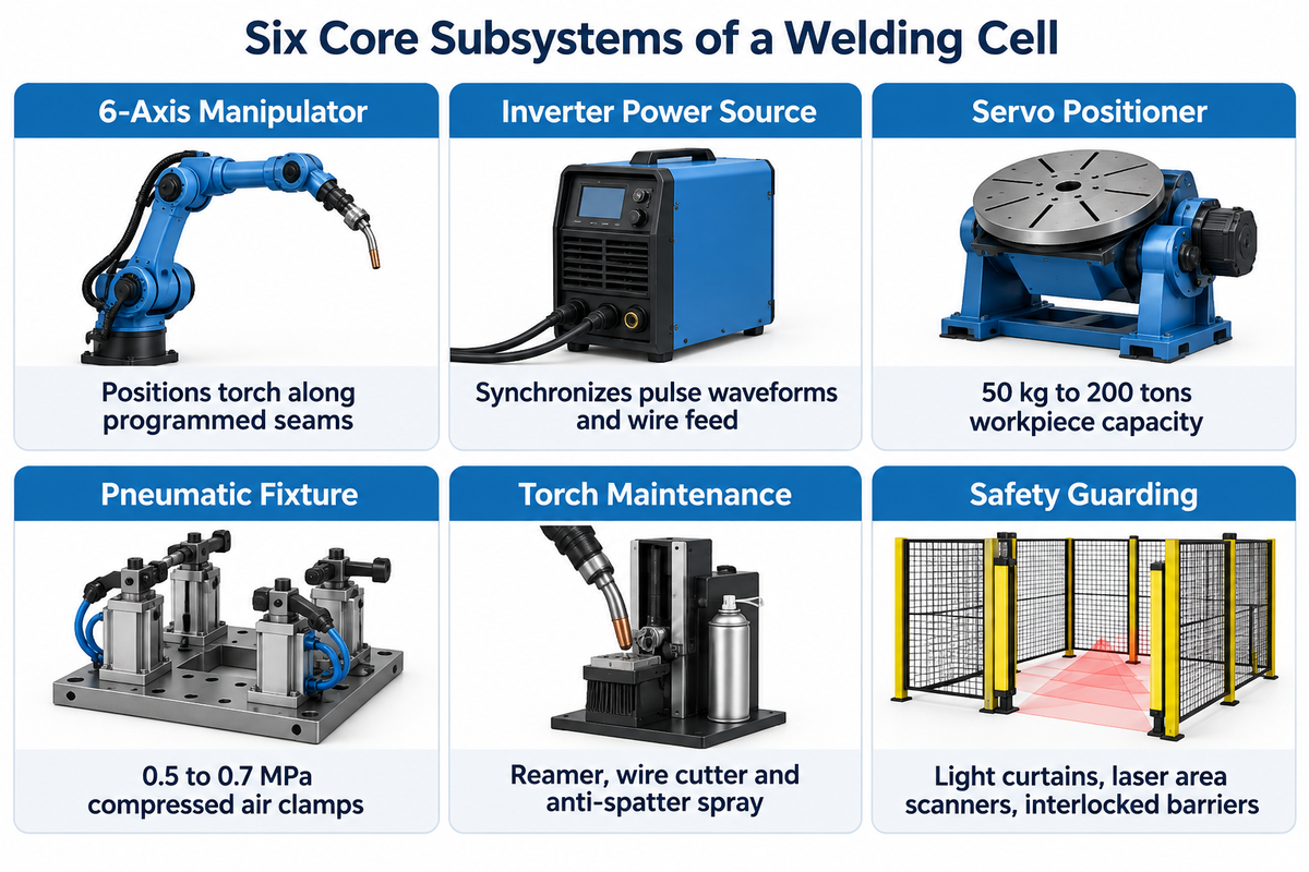
A weld cell is an enclosed manufacturing workstation. It groups a robotic manipulator, welding power source, workpiece positioner, clamping fixture, torch maintenance unit, and safety barrier into one coordinated system. Manual welders operate at 20% to 40% arc-on time. Automated welding cells maintain approximately 65% to 70% efficiency at hour 10 of a shift.
65%–70%shift hour-10 cell efficiency
98%target production cell uptime
4 minquick-change setup from 1 hour
In cellular manufacturing, each workcell processes a defined part family from tacked sub-assembly to finished weldment. Parts don’t require cross-bay forklift transfers between steps. This layout boosts shop floor productivity and cuts unplanned downtime between batches. Training programs such as the A-B Tech Robotic Welding Certificate program teach technicians to coordinate robot motion, fixture datum clamping, and arc parameter control. Shops evaluating a pre-engineered or custom system can review our foundational robotic welding cell planning checklist. They can also explore custom turnkey robotic welding cell configurations for heavy structural steel.
6-Subsystem Cell Readiness Audit (The 6-Subsystem Cell Readiness Audit)
The 6-Subsystem Cell Readiness Audit provides validation that all six interdependent hardware subsystems are adequately scaled and synchronized prior to signing a turnkey integration agreement.
First-time buyers concentrate on 6-axis robot arm, but that’s just one hardware component; five additional subsystems, located on the periphery of the entire system, impact cycle time, weld quality, and cell compliance.
- 6-Axis Hollow-Wrist Manipulator & Controller: Industrial robot arms from FANUC, ABB, KUKA, or Yaskawa Motoman move the torch along programmed weld seams. For instance, the FANUC ARC Mate 120iD (or FANUC ArcMate) sports a ±0.02 mm arm repeatability with a 25 kg wrist payload and 1,831 mm of reach.
- Digital Inverter Power Source & Wire Feeder: High-end multi-process welding power sources synchronize pulse waveforms and wire feed speed with robot travel speed. A Lincoln PowerWave class unit retails for roughly $10,000.
- Servo Workpiece Positioner: Single-axis turntables, 2-axis skyhook positioners, or headstock-tailstock rotators articulate heavy workpieces. Rotate every joint so it’s in the flat downhand position.
- Pneumatic or Hydraulic Workholding Fixture: Pneumatic clamps employ compressed air, typically at 0.5 to 0.7 MPa for cell pneumatic actuators. Hydraulic clamps use a pressurized hydraulic circuit to lock part geometries against thermal distortion.
- Automatic Torch Maintenance Station: A nozzle reamer, wire cutter and anti-spatter spray system service the torch after each weld cycle to prevent burnback and tool center point drift.
- Interlocked Safety & Fume Enclosure: Perimeter fencing and interlocked access guard against hazardous motion. Light curtains and laser scanners monitor personnel entering guarded areas. Welding screens protect against arc radiation.
Local exhaust hoods capture welding fumes.
What core components and safety systems are included in a complete industrial welding cell?
A complete industrial welding cell includes six core hardware components. These are a 6-axis robot arm with controller, an inverter power source with wire feeder, a servo workpiece positioner, workholding fixtures, an automated nozzle reamer station, and perimeter guarding with arc screens and fume extraction. Complete safety systems also require emergency stop circuits and an application-level ISO 12100 risk assessment. Teach and maintenance safeguards include three-position enabling switches, reduced manual speed limits, and Lockout/Tagout (LOTO) energy isolation.
EVST’s production maintenance guide notes that structured daily checks and 1,000-hour mechanical inspections keep a production work cell running at its 98% uptime target.
Welding Workstation Layouts: Single-Station vs Dual-Station Rotary Turntables
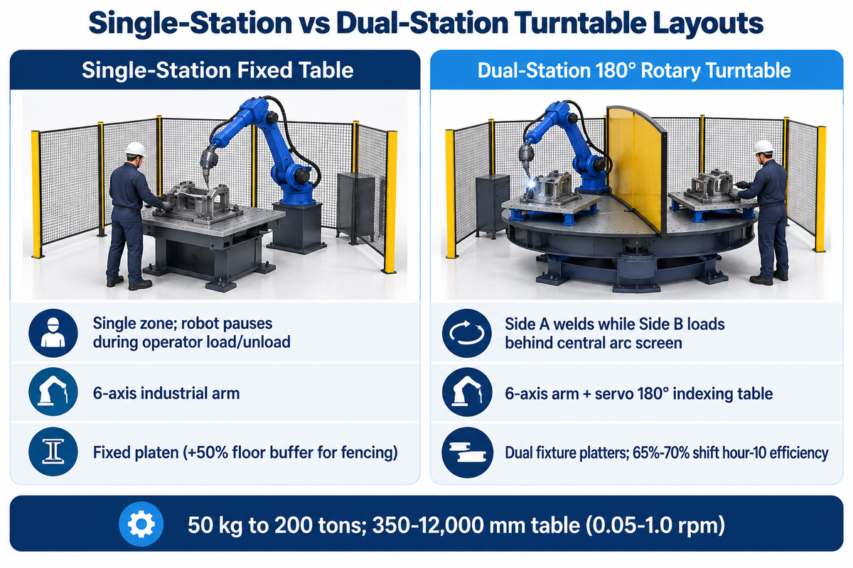
Single-station welding cells use one fixed table or positioner where the robot waits during part loading and unloading. Dual-station rotary turntable workstations feature a center arc-flash partition. The operators unload and load Side B while the robot welds Side A, thereby removing the operator’s wait time.
Choose a single-station workstation for long weld cycles where loading occupies a small fraction of cycle time. Select a dual-station rotary turntable when frequent part loading would otherwise idle the welding robot. Atan Robotics’ 2026 pricing guide notes that accommodating safety fencing and staging buffers frequently increases required floor space by 50%. As detailed in The Fabricator’s checklist for robotic welding success, matching part family volume to the station footprint prevents material-handling bottlenecks. Hirebotics’ 2026 planning guide shows that standardized quick-change setups cut changeover time from 1 hour to 4 minutes. That speed lets shops take on 20% more work without adding headcount.
Single-vs-Dual Turntable Arc-On Time Matrix
The Single-vs-Dual Turntable Arc-On Time Matrix compares nine industrial workstation types and positioner model categories by station loading mode, rotational axes, rated payload range, and target part geometry.
| Workstation Type & Model Category | Loading & Indexing Mode | Coordinated Axes | Catalog Capacity / Envelope Basis | Best-Fit Part Geometry & Batch Profile |
|---|---|---|---|---|
| Type 1: Portable Cobot Welding Cart | Manual table clamping; app-guided path setup in 4 min | 6-axis cobot arm | Modular slatted table; mobile shop cart | High-mix job shop brackets, frames, and small batches |
| Type 2: Single-Station Fixed Table Cell | Single zone; robot pauses during operator load/unload | 6-axis industrial arm | Fixed platen (+50% floor buffer for fencing) | Sub-assemblies with long multi-pass weld cycles |
| Type 3: Single-Axis Horizontal Rotary Turntable | Single zone with continuous 360° circumferential rotation | 6-axis arm + 1 servo rotation axis | 50 kg to 200 tons; 350–12,000 mm table (0.05–1.0 rpm) | Circular flanges, pipe spools, and cylindrical shells |
| Type 4: Dual-Station 180° Rotary Turntable | Side A welds while Side B loads behind central arc screen | 6-axis arm + servo 180° indexing table | Dual fixture platters; 65%–70% shift hour-10 efficiency | Automotive subframes, stamped brackets, and enclosures |
| Type 5: 2-Axis Tilt-Rotate Positioner Cell | Single or dual zone with tilt and 360° rotation for 1G/PA | 6-axis arm + 2 external servo axes | Sized for eccentric CoG offset and braking inertia | Valve bodies, gear housings, and multi-angle weldments |
| Type 6: 3-Axis Skyhook / L-Type Positioner Cell | Elevating, tilting, and rotating arm for full under-part access | 6-axis arm + 3 external servo axes | Full 1G downhand orientation on deep box sections | Complex agricultural cabs, chassis, and deep weldments |
| Type 7: Single Headstock-Tailstock Trunnion Cell | Overhead crane load with synchronized horizontal trunnion roll | 6-axis arm + 1 or 2 trunnion axes | Heavy-duty structural trunnion support up to 200 tons | Excavator booms, trailer axles, and long tubular frames |
| Type 8: Dual Headstock-Tailstock Ferris-Wheel Cell | Two opposing trunnion stations indexed across central partition | 6-axis arm + 3-axis ferris-wheel indexer | Continuous two-zone loading for long weldments | High-volume truck frames, axles, and structural beams |
| Type 9: 7th-Axis Linear Floor Track / Gantry Cell | Robot travels along linear rail between multiple work bays | 6-axis arm + 7th linear rail + positioner | Extended work envelope beyond 1,831 mm static arm reach | Bridge girders, wind tower sections, and ship panels |
How do you size a single-station versus a dual-station rotary turntable workstation for heavy metal fabrication?
Size a single-station versus a dual-station rotary turntable workstation by comparing part load time against arc time. Next, calculate combined weldment-plus-fixture mass, center-of-gravity eccentricity, and rotational braking inertia with a 1.25x to 1.30x dynamic safety margin. Industrial rotary turntables scale from 50 kg to 200 tons payload, 350 mm to 12,000 mm diameter, and 0.05 to 1.0 rpm rotation speed. Safety fencing and staging buffers add roughly 50% to the required floor footprint.
Engineers sizing turntable diameters and rotation speeds (0.05 to 1.0 rpm) can reference our heavy-duty rotary welding turntable sizing criteria. That guide matches table swing clearance against robot reach.
Matching the Welding Process to Your Cell: MIG/MAG, TIG, and Laser Welding Cells
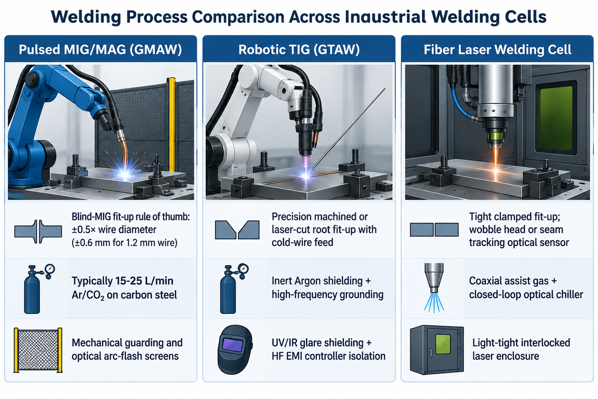
Pulsed MIG/MAG and flux-cored arc welding are primary options for structural fabrication. MIG/MAG and gas-shielded flux-cored welding use an external shielding-gas supply (typically 15 to 25 L/min for MIG/MAG on carbon steel), whereas self-shielded flux-cored welding does not. Robotic TIG cells are used for skinny stainless-steel assemblies, and fiber laser welding cells are used inside a light-tight interlocked laser cell.
Changing the welding process alters the torch cooling loop, wire feed mechanism, and safety enclosure design. In a documented Hirebotics marine fabrication case study, DeAngelo Marine Exhaust welded 200 inches per unit on a Coast Guard exhaust order. For the same weld length and pass count, increasing travel speed from 2 to 20 inches per minute reduces arc-on time by 90%. Loading, fixturing, and other non-welding operations remain part of the piece cycle. Safety practices for arc and gas shielding must also align with the OSHA Technical Manual Section IV Chapter 4 on industrial robot systems.
| Welding Process | Joint Fit-Up & Tracking Guidance | Shielding Gas & Cooling | Enclosure & Safeguarding Requirement | Primary Variety of Applications |
|---|---|---|---|---|
| Pulsed MIG/MAG (GMAW) | Blind-MIG fit-up rule of thumb: ±0.5× wire diameter (±0.6 mm for 1.2 mm wire) | Typically 15–25 L/min Ar/CO₂ on carbon steel | Mechanical guarding and optical arc-flash screens | Carbon steel chassis, brackets, heavy structural plate |
| Robotic TIG (GTAW) | Precision machined or laser-cut root fit-up with cold-wire feed | Inert Argon shielding + high-frequency grounding | UV/IR glare shielding + HF EMI controller isolation | Sanitary stainless tubing, aerospace thin-wall ducts |
| Fiber Laser Welding Cell | Tight clamped fit-up; wobble head or seam tracking optical sensor | Coaxial assist gas + closed-loop optical chiller | Specify a light-tight interlocked laser enclosure and verify its classification against applicable laser safety requirements | EV battery trays, electrical cabinets, low-distortion sheet |
When a single workcell is tasked with weld and handle parts or deburr weld seams, integrators can install a pneumatic tool changer on the robot wrist that lets the manipulator change tools automatically between a MIG torch and a laser scanner or grinding spindle, with no manual intervention. To spread speed and quality across demanding arc welding applications, match the torch cooling loop and wire feed mechanism to the welding process. Heavy-duty robotic welders also require durable cable dress packs to survive radiant heat in a harsh shop environment.
Unfenced Cobot Weld Cell vs Fenced 6-Axis Robotic Weld Cell
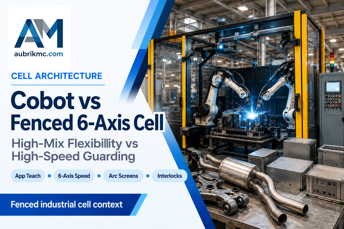
Collaborative welding cells are ideal for high-mix job shops. Operators program a new path in 4 minutes with app-assisted teach rather than 1 hour on a conventional teach pendant. Fenced 6-axis industrial robotic weld cells support high-duty-cycle, repetitive production.
Multi-axis positioners and high-speed travel are behind interlocked perimeter guarding.
Collaborative Cobot Welding Cell
- App-assisted path programming takes 4 minutes versus 1 hour on a traditional pendant
- ISO 10218-1 safety-rated monitored stop, speed and force limiting, and safety zones built in
- Reduced-speed settings and protective stops can lengthen non-welding travel between multiple welds
- Still requires UV/IR arc flash screens, spatter shields, and local fume extraction
Fenced 6-Axis Industrial Robotic Cell
- High-speed duty cycles with ±0.02 mm repeatability, 25 kg payload, and 1,831 mm reach (FANUC ARC Mate 120iD)
- Base 6-axis industrial manipulator hardware ranges from $50,000 to over $200,000
- Synchronizes external servo positioner axes for continuous 1G downhand welding
- Perimeter guards with interlocked access protect the robot hazard zone. Light curtains or laser area scanners provide presence sensing at designated access points
A widespread misconception is that an ISO 10218-1 collaborative robot can weld in an open shop bay without barriers. The American Welding Society Welding Digest guide to safe cobot welding states the rule clearly. All process risks including ultraviolet arc radiation, flying spatter, and toxic fumes must be mitigated before a human works nearby. Relia-Mation similarly notes that collision-detection sensors on a cobot arm don’t protect bystanders from arc flash, hot surfaces, pinch points, or sharp edges.
When should a fabrication shop choose an unfenced cobot welding cell over a fenced 6-axis robotic welding cell?
Choose a collaborative cobot welding cell when your shop runs high-mix, low-volume jobs and needs portable cart flexibility for diverse welding tasks. It fits teams where welders teach new paths manually in 4 minutes. Choose a fenced 6-axis industrial robotic weld cell for repetitive multi-shift production, synchronized heavy workpiece positioners, and high-speed travel enclosed with interlocked enclosures and optoelectronic sensors.
Sizing Robot Reach and Positioner Payload (kg) for Downhand (1G/PA) Welding
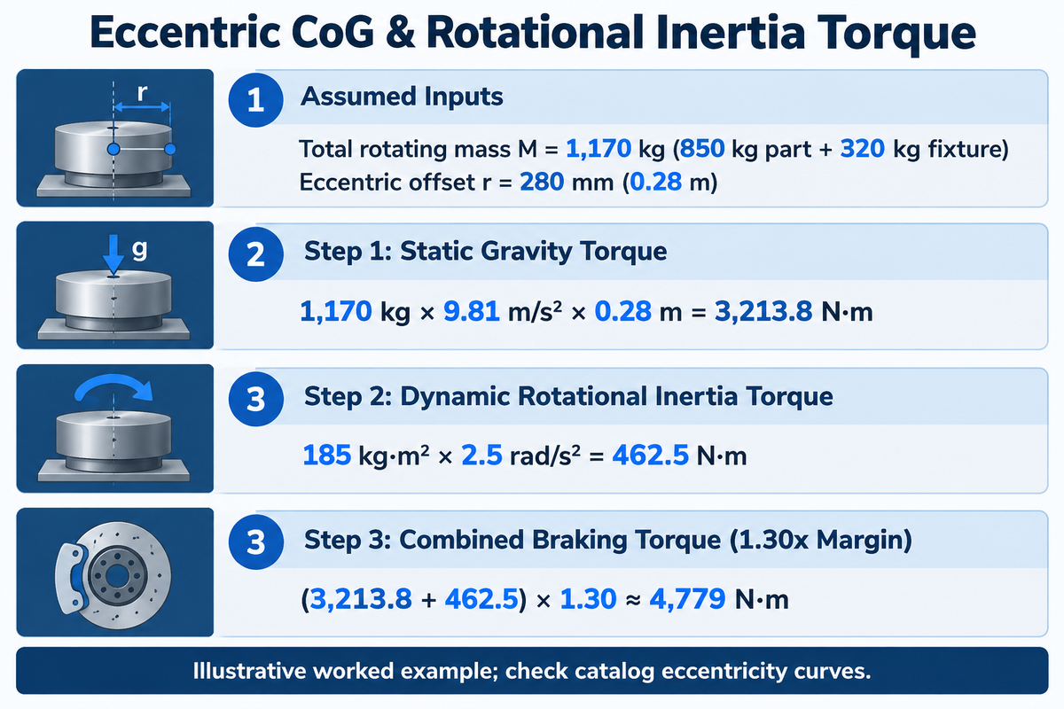
Sizing a welding cell requires separating robot wrist payload (such as 25 kg on the FANUC ARC Mate 120iD for the torch package) from workpiece positioner payload (50 kg to 200 tons). The example below combines eccentric gravitational torque and rotational inertia torque with a rate of assumed braking safety factor of 1.30x.
For instance, the FANUC ARC Mate 120iD carries a 25 kg maximum payload at the wrist with a 1,831 mm reach, ±0.02 mm repeatability, and IP67 wrist protection. That wrist payload is used only to hoist the welding torch, wire liner, and seam sensor. The heavy steel assembly rests on a servo welding positioner that tilts and rotates the weldment into the flat downhand (1G/PA) gravity position.
Synchronized workpiece positioners hold joints in advantageous welding positions. The deposition rate and undercut control also depend on welding parameters, torch angles, and joint fit-up, as explained in USPTO patent application US20210086288A1 for multi-station robotic welding cells. Consider our multi-axis servo welding positioner torque calculations for complex three-axis envelopes.
📐 Engineering Worked Calculation: Eccentric CoG & Rotational Inertia Torque
Assumed inputs (illustrative worked example): Assume a structural fabrication shop mounts an 850 kg steel excavator boom sub-assembly onto a 320 kg pneumatic fixture (total rotating mass M = 1,170 kg). The combined center of gravity (CoG) sits at an eccentric offset rcg = 280 mm (0.28 m) from the rotation axis. Rotational inertia is I = 185 kg·m² and emergency-stop angular deceleration is α = 2.5 rad/s².
- Step 1 (Static Gravity Torque): Tstatic = 1,170 kg × 9.81 m/s² × 0.28 m = 3,213.8 N·m.
- Step 2 (Dynamic Rotational Inertia Torque): Tinertia = I × α = 185 kg·m² × 2.5 rad/s² = 462.5 N·m.
- Step 3 (Combined Braking Torque with an Assumed 1.30x Safety Margin): Treq = (3,213.8 + 462.5) × 1.30 ≈ 4,779 N·m at the positioner output. This assumes that the gravitational and inertial torques are in the same direction during braking.
Engineering Verdict: On these inputs, the required combined braking output torque, including the 1.30x safety factor, is approximately 4,779 N·m. Select a positioner whose load-eccentricity curve supports the 1,170 kg rotating assembly at a 0.28 m offset and whose braking torque rating meets the calculated requirement. The calculated torque alone doesn’t establish a choice between specific tonnage models without checking catalog eccentricity curves. Every 1,000 hours of operation, maintenance teams must also inspect reducer grease condition, gear flex spline fretting, and output bearing play.
Robotic Welding Cell Cost Breakdown and Payback Calculation (2026)
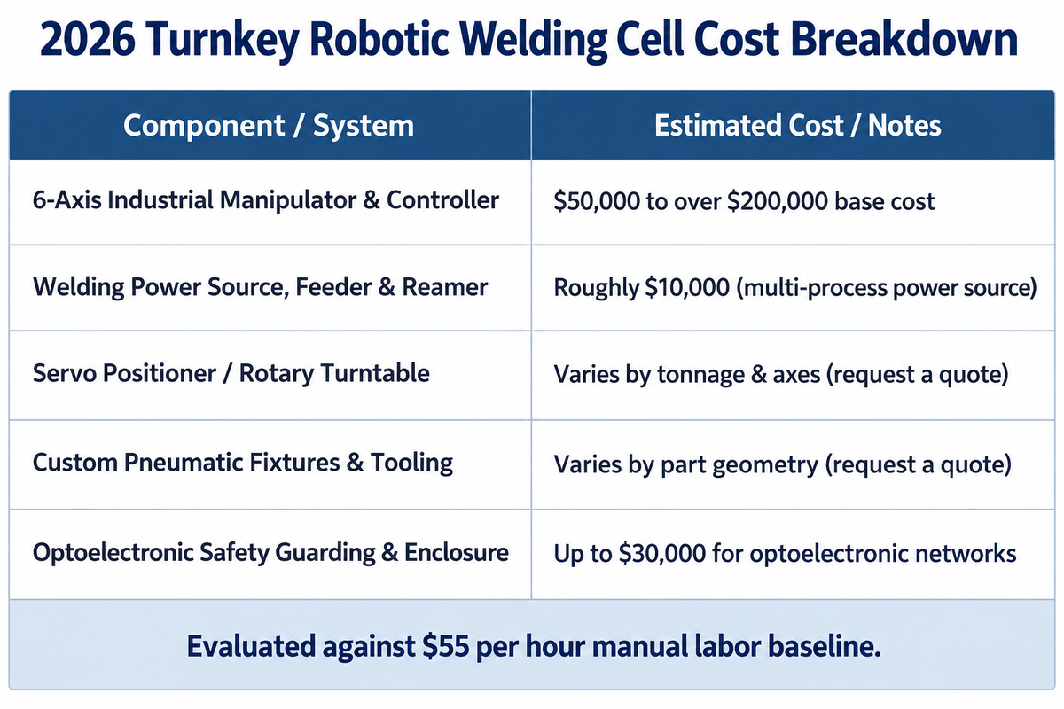
Ultimately, the sizing of positioner torque and reach defines the capital budget for a welding cell. Atan Robotics’ 2026 pricing guide notes that standard 6-axis industrial manipulator arms have a base cost of $50,000 to more than $200,000. High-end multi-process power sources retail for roughly $10,000, and optoelectronic safety networks add up to $30,000.
The price of turnkey cell depends on the positioner size and the number of fixtures.
How much does a robotic welding cell cost?
According to Atan Robotics’ 2026 pricing guide, base 6-axis industrial robot manipulators cost $50,000 to over $200,000 before integration. High-end multi-process welding power sources retail for roughly $10,000, and optoelectronic safety networks (laser area scanners and light curtains) add up to $30,000. Complete turnkey welding cell pricing varies by servo positioner payload (50 kg to 200 tons), custom pneumatic fixturing, and fume enclosure scope.
Some shops consider a used FANUC arm to reduce capex, though turnkey cells require a quote.
Skilled welder shortages have pushed fully burdened manual labor rates up to $55 per hour. Consequently, buyers evaluate cell investments by comparing total installed capital cost against annual labor and rework savings. As outlined in The Fabricator’s robotic welding project checklist, turnkey budgets must account for fixture engineering, optoelectronic safeguarding, and Factory Acceptance Testing (FAT).
| Cell Subsystem / Cost Component | 2026 Published Cost Benchmark (USD) | Budget Allocation Role | Scope & Cost Drivers |
|---|---|---|---|
| 6-Axis Industrial Manipulator & Controller | $50,000 to over $200,000 base cost | Core manipulator hardware | Reach (e.g., 1,831 mm), 25 kg wrist payload, controller software |
| Welding Power Source, Feeder & Reamer | Roughly $10,000 (multi-process power source) | Arc power & torch maintenance | Pulsed inverter, wire feeder, water cooler, nozzle reamer |
| Servo Positioner / Rotary Turntable | Varies by tonnage & axes (request a quote) | Workpiece articulation subsystem | 50 kg to 200 tons capacity; 350 mm to 12,000 mm diameter |
| Custom Pneumatic Fixtures & Tooling | Varies by part geometry (request a quote) | Datum clamping & quick-change | Quick-change subplates (4-min setup), 0.5–0.7 MPa air clamps |
| Optoelectronic Safety Guarding & Enclosure | Up to $30,000 for optoelectronic networks | Cell-level compliance & LEV hood | Light curtains, laser area scanners, interlocked barriers |
Total turnkey budgets and payback timelines depend on pneumatic fixture complexity and multi-shift arc-on utilization against the $55/hour manual labor baseline. They’re also affected by whether laser enclosures or centralized exhaust are included.
2026 Safety, Safeguarding, and Fume Extraction Standards (ISO 10218-2 & AWS D16.1)
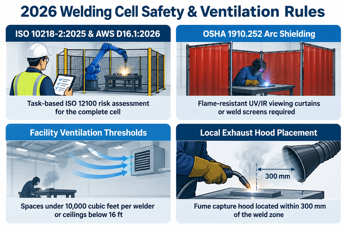
Industrial welding cell safety is addressed by ISO 10218-2:2025 for industrial robot system integration and AWS D16.1M/D16.1:2026 for robotic arc welding safety. The 2025 revision of ISO 10218 and ANSI/A3 R15.06-2025 enforce the Application-Safety Principle. Safety is evaluated as a property of the complete deployed application rather than the bare robot hardware.
The Association for Advancing Automation (A3) updated ISO 10218 FAQ explains the 2025 revisions of ISO 10218-1:2025 and ISO 10218-2:2025. These standards fold collaborative operating requirements (formerly in ISO/TS 15066:2016) directly into the normative robot safety standard. For North American shops, the AWS D16 Committee on Robotic and Automatic Welding pairs AWS D16.1M/D16.1:2026 with the AWS D16.3M/D16.3:2026 Risk Assessment Guide. Together, they guide hazard analysis across routine production and non-routine teach or maintenance modes.
- ✔ ISO 10218:2025 addresses robot and robot-cell safety. A manipulator supplied for integration and unable to perform its intended application independently can qualify as partly completed machinery under machinery legislation. Integrators and facility operators must conduct a task-based ISO 12100 risk assessment for the complete cell.
- Physical cages can be substituted with laser scanners or collaborative force-limiting devices in certain configurations. Nevertheless, flame-resistant UV/IR viewing curtains or weld screens are still required per OSHA 1910.252 to protect nearby workers from arc radiation.
- ✔ Mechanical ventilation is required for welding in spaces under 10,000 cubic feet per welder or with ceilings below 16 ft. According to Zhouxiang’s Ventilation Guide, local exhaust ventilation is required when welding stainless steel, lead, cadmium, beryllium, or chromium-containing metals regardless of room size.
- The daily maintenance checklist for EVST includes having the fume capture hood located within 300 mm of the weld zone and ensuring that the saturation indicators on the extractor filters are within their operational ranges.
Part Fit-Up Tolerances, Seam Tracking, and TCP Maintenance Rules
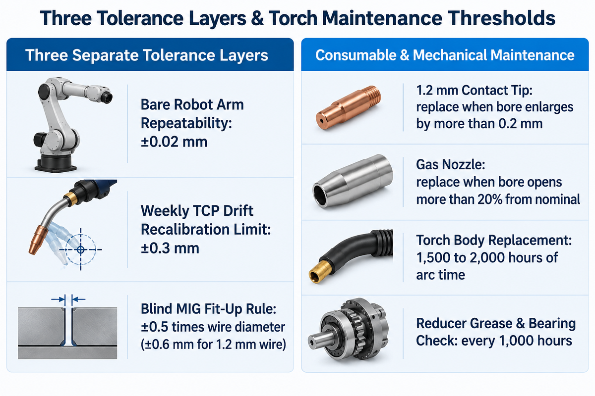
A preliminary fit-up rule of thumb for blind robotic MIG welding is ±0.5 times the wire diameter, equivalent to ±0.6 mm for 1.2 mm wire. Technicians must also check Tool Center Point (TCP) position weekly against a master reference pin.
Recalibrate the torch before returning to production if any axis shows drift beyond ±0.3 mm.
0.5x Wire-Diameter Fit-Up Rule (The 0.5x Wire-Diameter Fit-Up Rule)
For blind robotic MIG welding without seam tracking, a fit-up rule of thumb ( The 0.5x Wire-Diameter Fit-Up Rule ) is to keep part-to-part joint-gap and root-location variation within ±0.5 times the filler wire diameter.
There are three separate tolerance layers within a robotic workcell, and engineers need to differentiate between all of them. Bare robot arm repeatability sits at ±0.02 mm on models such as the FANUC ARC Mate 120iD. Weekly TCP verification triggers recalibration whenever any axis shows drift beyond ±0.3 mm.
Upstream part fit-up settles for the ±0.5x wire-diameter rule of thumb (±0.6 mm for 1.2 mm wire) in blind teach-pendant MIG welding. When upstream cutting or bending variation exceeds the blind-welding tolerance window, the workcell can integrate touch sensing, Through-Arc Seam Tracking (TAST), or real-time 3D laser vision measurement. Consistent datum clamping is just as important as described in our guide to precision pneumatic welding fixture datum design.
We also recommend referring to the OSHA Technical Manual on industrial robot maintenance safeguarding.
Do
- Verify TCP position weekly against a reference pin and recalibrate before production if any axis drifts beyond ±0.3 mm
- Replace 1.2 mm contact tips as soon as the bore enlarges by more than 0.2 mm
- Replace shielding gas nozzles when the bore opens more than 20% from nominal or collects fused spatter
- Schedule torch body replacement at 1,500 to 2,000 hours of high-duty-cycle arc time
Don’t (Practices to Avoid)
- Do not confuse bare manipulator arm repeatability (±0.02 mm) with the ±0.3 mm weekly TCP drift recalibration threshold
- Do not send variable flame-cut plates into a blind robotic weld cell without touch sensing, TAST, or laser seam tracking
- Do not run pneumatic actuators, torch cleaners, or air-cooled torches outside the 0.5 to 0.7 MPa compressed air band
- Do not skip 1,000-hour inspections of reducer grease condition, gear flex spline fretting, and output bearing play
How to Specify a Turnkey Robotic Welding Cell Manufacturer or Integrator
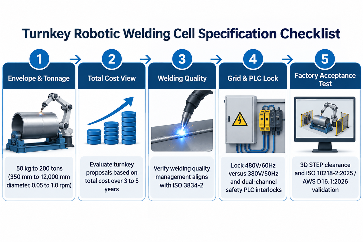
Specify a turnkey robotic welding cell manufacturer by matching your part envelope and positioner payload (50 kg to 200 tons) to the supplier’s mechanical fabrication capacity, robot brand integration experience, and ISO 3834-2 / ISO 10218-2:2025 compliance documentation.
Which robotic welding cell manufacturers and turnkey integrators are best for structural and heavy-plate fabrication?
Global robot manufacturers including FANUC, ABB, KUKA, and Yaskawa Motoman supply 6-axis industrial manipulators such as the 25 kg payload, 1,831 mm reach FANUC ARC Mate 120iD. Heavy-duty positioner and workstation manufacturers such as Wuxi ABK Machinery (Aubrik) build rotary welding turntables and servo positioners rated from 50 kg to 200 tons (350 mm to 12,000 mm diameter, 0.05 to 1.0 rpm). These positioners integrate directly with tier-one arms for structural fabrication.
Hirebotics’ 2026 automation planning guide recommends evaluating turnkey proposals based on total cost over 3 to 5 years. That 3-to-5-year view covers your team’s time to program changes, integrator support responsiveness, and ease of scaling to additional applications. For safety-critical structural weldments, verify that the supplier’s welding quality management aligns with ISO 3834-2. ISO 3834-2 complements ISO 9001 for organizations where welding is a primary manufacturing process. Also require a mandatory, task-based ISO 12100 risk assessment for the complete deployed application under ISO 10218:2025, as outlined in A3’s ISO 10218:2025 compliance guidance. Cross-border turnkey buyers must lock primary power voltage (480V/60Hz versus 380V/50Hz) and dual-channel safety PLC interlocks into the Factory Acceptance Test (FAT) protocol before shipment. You can compare supplier capabilities in our analysis of global robotic welding system integrator capabilities.
Key takeaway
During Factory Acceptance Testing, your 3D STEP part files support access and clearance assessments. Cell safety validation also requires tests of the assembled system’s guarding, interlocks, and safety functions against ISO 10218-2:2025 and AWS D16.1M/D16.1:2026.
Frequently Asked Questions (FAQ)
Q: How much floor space does a standard robotic welding cell require?
Atan Robotics’ 2026 layout guidelines note that perimeter safety fencing and part staging buffers frequently increase required shop floor space by 50% over the bare workstation footprint.
A small portable cobot cart or single-station table needs a less extensive bay than a dual-station rotary turntable or linear gantry track. A cell perimeter layout plan must account for any light-curtain approach zones, fume extraction hoods, and clearance space needed for forklift or overhead crane loading.
Q: What is the typical arc-on time of a robotic weld cell compared to manual welding?
Manual welders have 20% to 40% arc-on time because the balance of the shift is used for part positioning, setup, and inspection. Automated welding cells maintain approximately 65% to 70% efficiency even at hour 10 of a shift.
In a manual booth, the operator cancels welding to flip heavy workpieces, chip slag, and re-clamp. Two-Station positioner load doesn’t require the operator to wait because side B is loaded while robot welds on side A behind an arc-flash barrier.
Q: Can one robotic welding cell handle multiple part numbers in a high-mix job shop?
Yes, high-mix job shops run multiple recurring part families on a single robotic welding cell by coupling fast-change pneumatic fixtures with stored controller programs and app-based path teaching.
Hirebotics’ 2026 automation guide shows that standardized quick-change setups cut changeover time from 1 hour to 4 minutes. The hour it takes to reposition fixtures and tools in the old process is now creating parts. Fabrication shops can increase the amount of work they can do 20% with no increase in heads.
While the robot welds on Side A, the operator stages the next part geometry on Side B.
Q: How often should you verify and recalibrate the Tool Center Point (TCP) in a welding cell?
Verify TCP accuracy weekly against a fixed master reference pin and recalibrate before returning the cell to production whenever any axis shows more than ±0.3 mm drift.
EVST’s production maintenance schedule also requires a complete multi-point TCP recalibration following any torch collision or gooseneck replacement to reduce the risk of fillet root misses.
Q: What is the difference between Through-Arc Seam Tracking (TAST) and laser vision seam tracking?
Through-Arc Seam Tracking (TAST) technique detects the current and voltage changes across a torch weave. 3D laser vision systems that use a laser stripe, on the other hand, project it in front of the welding arc to measure joint gap width and root mismatch in real time.
Laser vision locates seams when through-arc tracking signals are inadequate. Taught path can also be used for thin-sheet, lap-joint and aluminum assemblies when fixturing ensures that the joints remain in the qualified welding tolerance.
Q: Do robotic welding cells require water-cooled torches or air-cooled torches?
For continuous high-current welding, water-cooled torches are appropriate. Air-cooled torches are also suitable for industrial robot cells when the specified current and duty-cycle limits for the shielding gas include the welding schedule.
On high-duty-cycle cells, torch bodies usually have a service life of 1,500 to 2,000 hours of arc time, so daily inspections of coolant connections, contact tips, and nozzles remain essential.
Q: What facility utilities are needed before installing a turnkey industrial welding cell?
A turnkey industrial welding cell requires three-phase primary electric power (such as 380V to 480V matched to the plant grid) and clean dry compressed air at 0.5 to 0.7 MPa. It also requires regulated shielding gas delivering 15 to 25 L/min (for MIG/MAG on carbon steel) and mechanical ventilation.
The 0.5 to 0.7 MPa compressed air line operates pneumatic actuators, torch cleaner units, and air-cooled torches. Heavy duty servo positioners transfer static, dynamic and overturning loads to foundation. Suitable anchorage can use cast-in, mechanical, or chemical anchors sized for those loads and the concrete conditions.
Engineer Your Custom Turnkey Robotic Welding Cell
Are you automating structural brackets on a 180-degree dual-station rotary turntable or integrating a 200-ton headstock-tailstock positioner with a 6-axis FANUC, ABB, KUKA, or Yaskawa robot arm?
Our engineering team creates fully engineered welding cells around your build-to part drawings with the right takt-time.
About This Engineering Analysis
This technical guide combines robot and welding safety standards, including ISO 10218-2:2025 and AWS D16.1M/D16.1:2026, with U.S. OSHA welding regulations in 29 CFR 1910.252. It pairs those rules with heavy-duty positioner and rotary turntable sizing data from our manufacturing facility. All eccentric center-of-gravity torque equations, TCP drift thresholds, and subsystem cost benchmarks were cross-checked against primary standards and field maintenance protocols. Reviewed by the Wuxi ABK Machinery Co., Ltd. (Aubrik) technical team.
References & Sources
- Robotic Welding Certificate Curriculum & Cell Operation Standards – Asheville-Buncombe Technical Community College (A-B Tech)
- Checklists for Robotic Welding Success – The Fabricator (Fabricators & Manufacturers Association)
- OSHA Technical Manual (OTM) Section IV, Chapter 4: Industrial Robot Systems and Robot System Integration – U.S. Department of Labor, Occupational Safety and Health Administration (OSHA)
- Welding Digest: Safe Cobot Welding Hazard Mitigation – American Welding Society (AWS)
- US20210086288A1: Multi-Station Robotic Welding Cell and Synchronized Workpiece Positioner – United States Patent and Trademark Office (USPTO / Google Patents)
- ISO 10218-2: Robots and Robotic Devices: Safety Requirements for Industrial Robots (Part 2: Robot Systems and Integration) – International Organization for Standardization (ISO)
- AWS D16.1M/D16.1:2026 Specification for Robotic Arc Welding Safety – American Welding Society (AWS)
- Updated ISO 10218:2025 Industrial Robot Safety FAQ – Association for Advancing Automation (A3)
- AWS D16 Committee on Robotic and Automatic Welding (AWS D16.3M/D16.3:2026 Risk Assessment Guide) – American Welding Society (AWS)
Related Articles
- Robotic Welding Cell Guide: Core Planning Steps for First-Time Automation Buyers
- Heavy-Duty Welding Turntable Selection: Diameter, RPM, and Load Sizing
- 3-Axis Welding Positioners Selection Guide for Complex Weldments
- Welding Fixture Design: Clamping Repeatability and Thermal Distortion Control
- Top Robotic Welding System Manufacturers and Turnkey Integrators Compared