Get in Touch with Aubrik Company

Welding Positioners & Turntables — 50 kg to 50 t
Rotary · Pipe · Turntable · Heavy-Duty | ISO 9001 & CE Certified | ±0.05 mm | 0.03–30 RPM
50 kg–50 t Load range, one supplier
±0.05 mm Rotary repeatability
0.03–30 RPM Stepless speed (TIG-slow)
0–135° Tilt range
ISO 9001 + CE Certified, 50+ countries
12 months Warranty · MOQ 1 · OEM
The Hidden Cost of Poor Workpiece Positioning
A welding positioner holds, rotates, and tilts a workpiece so every joint sits in the flat, downhand position. When welders fight gravity instead-reaching overhead, walking around a part, stopping and restarting the arc-weld quality and throughput both suffer.
The root cause is ergonomic, not skill-related. Stressful postures are also inefficient postures: every awkward reach adds time and accelerates the wear that drives work-related musculoskeletal disorders, which OSHA flags as a leading controllable hazard in fabrication.
- Multi-pass starts and stops on out-of-position welds raise porosity, undercut, and lack-of-fusion defects.
- Manual repositioning of heavy weldments is the #1 source of operator fatigue and lost cycle time.
- Inconsistent travel speed around a girth weld starves or piles the bead.
The fix is to move the part, not the welder. A motorized positioner presents the seam in the optimal position and holds a constant surface speed, which is why OSHA names repositioning equipment an engineering control that both lowers injury rates and raises productivity. That dual payoff is the entire reason this category exists — and the rest of this page shows how to pick the right one.
The expensive part is what poor positioning does over a year: rework that can reach 20-30% of a batch, scrapped weldments, and the delivery slip that follows. A regional steel fabricator welding 30-ton vessels feels this as lost throughput-the exact problem Aubrik positioners remove, because every joint reaches the flat position. Our engineers size each Aubrik unit to that failure mode, not to the nameplate.
System Engineering See where a positioner pays back fastest in your shop — get a custom engineering assessment →The Aubrik Welding Positioner & Turntable Range — Models, Specs & Selection
Aubrik builds the full positioner ladder under one roof, from a 50 kg benchtop turntable to a 50-tonne custom headstock unit. Four product families cover the way real fabricators search and buy-by workpiece type, not by an arbitrary model series.
Rotary Welding Positioner
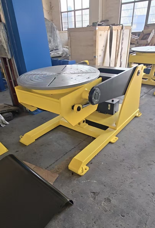
RW-100 / RW-500 / RW-2000 100–2,000 kg (50 t custom) 3/4-jaw chuck, 6–12 in 0.03–30 RPM · 0–135° tilt ±0.05 mm repeatability
View Rotary Positioners →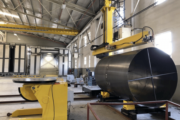
Pipe Welding Positioner
BW / WP / HD series 1–50 tonnes Pipe dia 40–2,500 mm VFD stepless · 0–135° Self-centering chuck + rollers
View Pipe Positioners →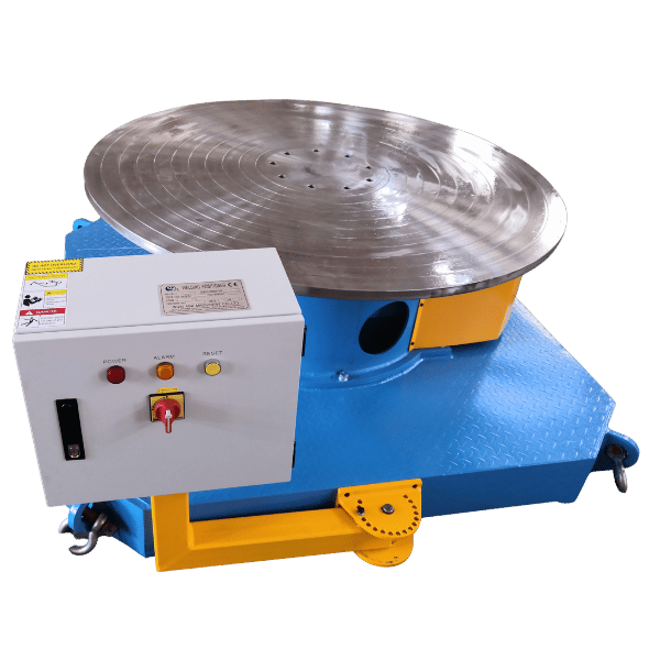
Welding Turntable
BY-50 … BY-2000 50–2,000 kg Table 200–600 mm Runout < 0.02 mm MIG / TIG / MMA / plasma
View Welding Turntables →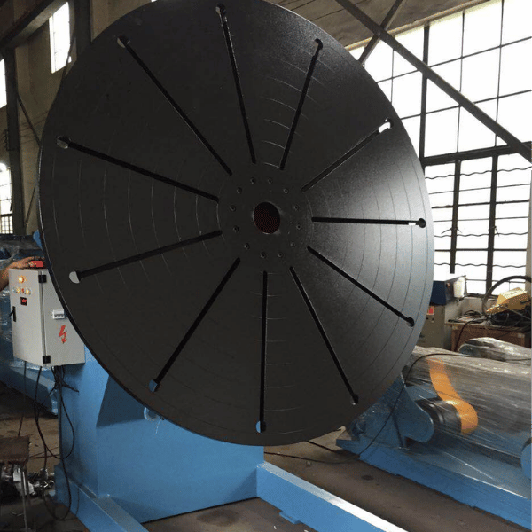
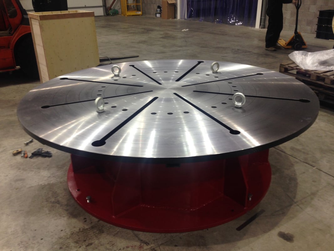
Heavy-Duty Welding Positioner
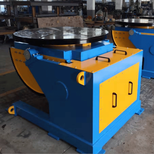
HB300 / HB3000 / HB20T 300 kg–20 t (50 t custom) ±0.5° index · Siemens PLC Q355B frame · T-slot table ATEX explosion-proof option
View Heavy-Duty Positioners →Rotary positioners and turntables grip round, flat, or bracketed parts with a chuck or T-slot faceplate; pipe positioners spin cylindrical spools on a self-centering chuck and idler rollers; heavy-duty headstock units carry pressure vessels and wind-tower cans between centers. The positioner principle is old and well-proven — 360° rotation with eccentric-adjustable rollers appears in patent literature back to the 1950s.
Buying the wrong type is an expensive problem that can add 30% to setup time: a pipe welding rotator suits a long spool but fails on an offset bracket, while a rotary welding table or a welding manipulator fits a different job entirely. A US buyer fabricating 20-ton pressure vessels needs the HB headstock, not a benchtop-which is why Aubrik maps each family to a workpiece class, because mismatched equipment is the #1 source of slow, costly setup.
Capacity & Precision Selector
| Family | Rated load | Table / pipe dia | Speed (RPM) | Tilt | Precision | Control |
|---|---|---|---|---|---|---|
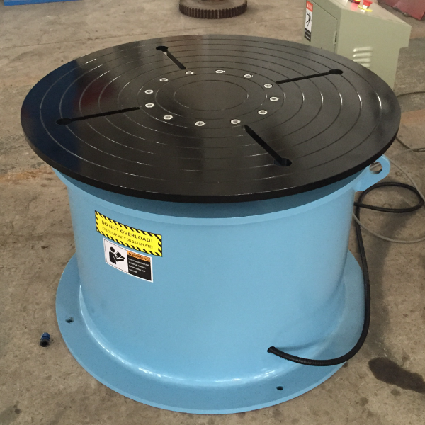
| Turntable (BY) | 50–2,000 kg | 200–600 mm | 0.08–5 | 0–90° | runout <0.02 mm | VFD / foot pedal |
| Rotary (RW) | 100–2,000 kg | chuck 6–12 in | 0.03–30 | 0–135° | ±0.05 mm | Manual / PLC / servo |
| Pipe (BW/WP/HD) | 1–50 t | 40–2,500 mm | 0.02–3 | 0–135° | self-centering | VFD / PLC |
| Heavy-Duty (HB) | 300 kg–50 t | 650–2,500 mm | 0.05–2 | 0–135° | ±0.5° index | Siemens PLC + HMI |
All models accept MIG (GMAW), TIG (GTAW), stick (SMAW), and submerged-arc processes, and are rated for 220 V or 380 V at 50/60 Hz, meaning the same unit can be shipped to any US, EU, or Middle-East shop, phase converter free. The trades this equipment is used for: pressure vessels, piping, wind power, ship building, heavy machinery, auto and general steel fabrication.
Not sure which family fits your part?
Get a model recommendation from an Aubrik engineer →How to Choose a Welding Positioner: The SOLVE Sizing Framework
Here is the single most expensive sizing mistake in this category: assuming the headline load rating is the load you can actually weld. It is not. A rated capacity only holds when the part’s centre of gravity sits on the table centreline — the moment the CG moves up or out, usable capacity falls hard.
Torque, not weight, is the cause. Usable capacity follows Effective Load = Maximum Rated Torque ÷ distance from the axis to the CG, so an offset or tall workpiece de-rates a unit sharply.
Eccentric / CG-Height De-Rating — why “rated load” lies
Even if a positioner is rated for say 5000 pounds on line, it is likely only ~ 1/2 that on its side, and it will drop further as CG rises.
| CG height above table | 4 in | 8 in | 12 in | 16 in | 20 in |
|---|---|---|---|---|---|
| Usable capacity (lb) | 325 | 226 | 173 | 140 | 118 |
Same machine, 64% less usable capacity at 20 in versus 4 in. Here is the honest version: the honest load number is the eccentric one, not the headline, and there is a real trade-off between rotation speed and holding torque you must size for. Both ratings sit on the Aubrik data sheet, so you size to physics, not to a marketing number.
S · O · L · V · E
S
Sum of the Real Load. Combine weight of: largest workpiece + any fixturing, chucks, clamps etc. Size on the heaviest workpiece, not your average workpiece.
O
Off-line COG of workpiece: The center of gravity and how far its offset from the table’s center.
L
Load Chart (NOT nameplate!): The center of gravity offset divided by safety factor (recommend 1.5 to 2) for use on our eccentric load chart.
V
Velocity: This is related to surface speed, recommend 150-400 mm/minute for hand welding or up to 1500 mm/minute for SAW; you’ll verify that your RPM range for the COG offset and part dimension covers your desired surface speed.
E
Environment: a hundred percent duty-cycle for robot cell application, proper ground for all the welding amperage. And correct for fieldbus for robotic cell, or the right controller for the welding system you have.
That last point is the spec nobody prints. Weld return current must reach the workpiece through a rated rotary ground (slip-ring or brush); if it travels through the bearings instead, it arc-pits them and the drive fails in months. Every Aubrik unit rates the grounding path to the welding amperage — the eccentric-roller and rotation design principles trace straight back to foundational positioner patents.
Want this as a one-page check list?
Get the SOLVE Sizing Guide & load calculator →Welding Positioner vs Manual Fixturing vs a Typical Budget Import
Most positioner sales come down to two comparisons: will it outperform a manually fixtured part, and is a quality positioner better than the lowest-cost import. Both are settled with numbers, not claims — the positioner principle itself is long documented in the patent record.
Positioner vs manual repositioning
| Factor | Manual fixturing | Aubrik positioner |
|---|---|---|
| Joint position | out-of-position, overhead | flat / downhand, every pass |
| Arc starts/stops per girth weld | many (walk-around) | one continuous pass |
| Travel speed control | hand-paced, variable | 0.03–30 RPM stepless |
| Operator posture | reaching / bending | neutral (waist–shoulder) |
Aubrik vs a typical budget import
| Spec buyers actually check | Typical budget import | Aubrik |
|---|---|---|
| Minimum rotation for TIG | ~2 RPM (too fast) | 0.03 RPM, steady |
| Load rating published | headline number only | horizontal + eccentric |
| Weld-current grounding | none rated (bearing risk) | rated rotary ground |
| Voltage / frequency | single market | 220/380 V, 50/60 Hz |
| Certification | none shown | ISO 9001 + CE |
| Warranty & service | eBay-style, parts scarce | 12 mo + overseas engineer |
The budget-import column is not a strawman — it is the exact list of complaints welders post about sub-$300 units: tables that cannot turn below 2 RPM for TIG, headline ratings that drop a weldment when tilted, and no replacement parts after the sale. As a direct manufacturer, not a box-shifter, Aubrik flips each of those columns.
TCO ANALYSIS
ROI & Total Cost of Ownership of a Welding Positioner
Sticker price is the smallest number in this equation. Look at what each positioner does to labour hours, rework, and the machine’s own lifespan:
3 levers that move TCO more than purchase price: labour-in-position, first-pass yield, and bearing life
TCO model — engineering basis below. Outcome figures are Aubrik-reported, application-dependent.
- Labour in position — rotating the seam to downhand removes walk-around time and the awkward postures OSHA links directly to lost productivity.
- First-pass yield — a constant surface speed in the flat position cuts undercut and lack-of-fusion, lowering NDT failures and rework.
- Bearing life — a rated rotary ground keeps weld current out of the bearings, protecting the costliest component from arc-pitting.
- Right-sized capex — sizing on the eccentric chart avoids both a unit that stalls and an oversized unit you overpaid for.
In Aubrik-reported projects — a wind-flange line and a 20-tonne pressure-vessel cell — customers cited materially lower rework and faster cycle times after switching from manual handling. Treat those as directional: the durable, defensible return is the engineering logic above, which holds in any shop.
INTEGRATION SPECIFICATION
Robot Integration & Control Engineering
In a robot cell, the positioner ceases to be a turntable and becomes an auxiliary axis. By using coordinated motion, the robot and the positioner can move in tandem—meaning the tool-centre-point that crafts the weld can keep a steady torch angle and speed—all while traveling along an ever-moving joint-no stop-reposition-restart condition.
However, for this to occur—three conditions must be simultaneously satisfied, and a low-cost solution normally will neglect at least one:
- Synchronized axes: the positioner must be usable as an intelligently commanded axis, rather than a simple on/off platform.
- Fieldbus support: EtherCAT, PROFINET, or DeviceNet—your controller compatible. We run a Siemens PLC, with HMI, standard interfaces.
- Support for at least three biggest robot brands: FANUC, ABB and KUKA.
Continuous-duty matters in automation
Robots take no cooling breaks, so the motion system needs a 100% duty-cycle drive and grounding rating. An HB-series heavy-duty unit pairs a Q355B stress-relieved frame, ±0.5° index repeatability, and an optional ATEX explosion-proof build for oil, gas, and battery-plant cells.
This is the depth integrators actually ask about — named protocols, named robot brands, a stated material grade, and a real index tolerance — rather than “advanced control options.” Three-axis coordinated positioning is well-established in the patent record.
Get this wrong and the cost is brutal: a robotic welding positioner that back-drives or loses sync forces manual rework and can idle a cell for 2–3 days. A US buyer in automotive running a 5-ton fixture sees this risk first — the problem Aubrik solves, because the HB drive is rated for continuous coordinated motion. Each Aubrik cell is verified on the customer’s robot brand before shipment.
Planning an automated cell? Request a detailed integration spec for your robot →
COMPLIANCE & SAFETY
Certifications & Welding-Code Compliance
This is where an honest answer beats a marketing one. There are two different kinds of standards in welding, and a credible supplier never blurs them.
STANDARD ID
APPLICATION SCOPE
STATUS
■ MACHINE-LEVEL CERTIFICATION
ISO 9001
Company QMS
HELD
CE / EN ISO 12100
Machine safety
HELD
■ PROCESS-LEVEL COMPLIANCE
AWS D1.1
Structural steel
ENABLES
ASME VIII
Pressure vessels
ENABLES
API 1104
Pipeline welds
ENABLES
EN 1090-2
EU steel exec.
ENABLES
What Aubrik holds vs what Aubrik enables
A positioner carries the certifications that apply to a machine: ISO 9001 for build-quality management and CE marking under the EU Machinery Directive, which requires an EN ISO 12100 safety risk assessment. ISO 9001 and CE are the only standards a positioner can legitimately be certified to.
Welding codes are a different matter: AWS D1.1, ISO 3834-2, ASME Section VIII, API 1104, EN 1090-2, and IEC 61400 govern the weld and the fabricator’s quality system, not the equipment. Aubrik positioners are built to support fabrication to those codes — the constant surface speed and flat-position access that code-compliant welds require. We do not claim the machine is “ASME certified,” because no positioner is.
Procurement Guide: Pricing, Lead Time, Warranty & Global After-Sales
The biggest objection to buying a positioner direct from a Chinese manufacturer is not price — it is what happens after the crate arrives. We answer that objection with terms, not promises.
Pricing is direct-from-factory, with no distributor markup between you and the people who build the machine. Because every unit is configured to the part it will weld, the right number comes from your specification — load, chuck, tilt, control, and destination — not a shelf price. The quality-management discipline behind that build is the same ISO 9001 system that underpins the warranty.
“We rate the grounding path to the welding amperage on every unit, and we publish the eccentric load chart, not just the centreline number. Those two specs decide whether a positioner lasts ten years or fails in one — so we put them on the data sheet.”
What an Aubrik order actually commits to
- Lead time — standard models 7–15 working days; custom builds 15–30 days.
- MOQ 1 and OEM — single-unit orders, plus customer-specified table, chuck, control, and capacity.
- Warranty — 12-month free cover for manufacturing defects and component failure.
- After-sales — long-term spare-parts supply and overseas on-site engineer service across 50+ export countries.
- Power — shipped for your grid (220 V or 380 V, 50/60 Hz), so no phase-converter surprise.
[SYS-FACILITY] VISUAL INSPECTION
Manufacturing Facility & Production Floor
ENGINEERING TOOLS
Engineering Calculation Tools
Utilize these engineering tools to determine accurate load capacities, travel speeds, and equipment configurations for your fabrication requirements.
TOOL.01
Welding Positioner Load Calculator
LAUNCH CALCULATOR →TOOL.02
RPM ↔ Surface (Travel) Speed Converter
LAUNCH CONVERTER →TOOL.03
Welding Positioner Family Selector
LAUNCH SELECTOR →TECHNICAL KNOWLEDGE BASE
Frequently Asked Questions
01
How do I size a welding positioner for my workpiece?
Add the heaviest part to all fixture and clamp weight, apply a 1.5–2.0× safety factor, then read the eccentric load chart at your centre-of-gravity offset — not the headline rating. Vertical (tilted) capacity is roughly half the horizontal number and drops further as the centre of gravity rises above the table. When you are unsure, send us the part drawing and an Aubrik engineer will size it with you.
02
Can the table turn slowly enough for TIG?
Yes. Aubrik rotary positioners run a stepless VFD drive from 0.03 RPM, well below the ~0.3–0.5 RPM that root and cap TIG passes need on larger diameters. Many budget units bottom out near 2 RPM, which is the most common TIG complaint on welding forums.
03
How is welding current grounded so it does not wreck the bearings?
Through a rated rotary ground (slip-ring or brush) sized to your welding amperage, so return current bypasses the bearings. Without it, current arcs across the ball-to-race contact and pits the bearing — a frequent failure on unrated imports.
04
What voltage do Aubrik positioners run on?
220 V or 380 V at 50/60 Hz. To be specified upon order; requires no phase converter.
05
Can it integrate with Fanuc, ABB, or KUKA robot cells?
Yes, SEMI-AUTOMATIC & HEAVY DUTY units are based on a SIEMENS PLC that has ETHERCAT / PROFINET / DeviceNet interfaces that allow for synchronized, external-axis operation with major robot vendors.
06
What is the lead time, warranty, and minimum order?
7-15 working days for standard units; 15-30 working days for custom-built units. 1-year warranty; MOQ is 1; OEMs welcome; ATEX explosion-proof optional.