Get in Touch with Aubrik Company

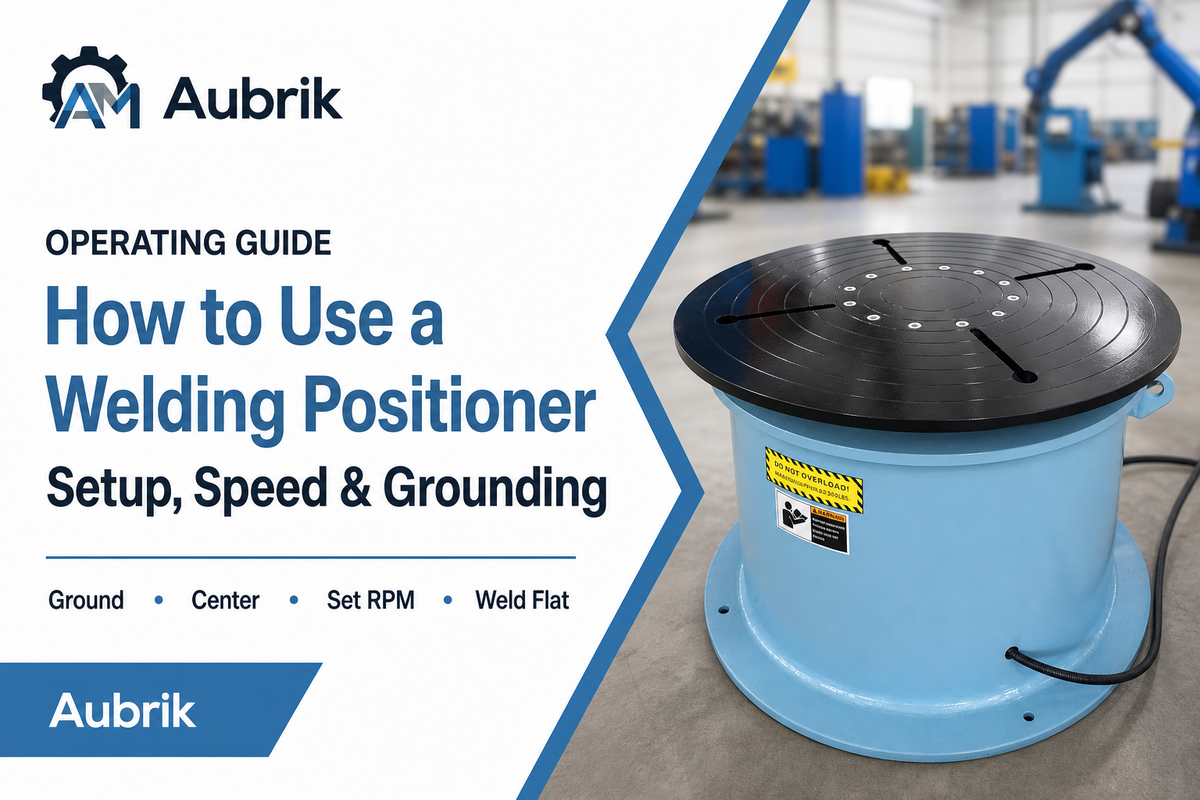
Updated July 2026
Use a welding positioner by securing it to a flat surface, following the manufacturer’s grounding path to the workpiece, centering the load and setting a stable speed for the joint. Stop before welding if the part wobbles, the cable heats or the table moves unexpectedly. Verify clamping, balance, emergency stop and cable routing before resuming the arc.
Quick Specs: Welding Positioner Operating Envelope
| Table / faceplate capacity | 10 kg – 100 t (rated at the faceplate, CoG on-axis) |
| Tilt range | 0–135° (bring the seam downhand/1G) |
| Rotation (surface) speed | ~40–2,000 mm/min at the workpiece surface, process-dependent |
| Turntable RPM | Benchtop 0–2.5 rev/min; heavy tables ~0.05–2 rev/min |
| Workholding | 3-jaw self-centering chuck, fixture, or bolt-down slots |
| Grounding | Work lead to bare table/faceplate; brush pickup on rotating tables |
| Control | Variable speed, forward/reverse, foot pedal or remote start |
In brief: Set up a welding positioner by bolting it firmly to a flat surface. Connect the workpiece ground directly to the positioner’s table or chuck face-never to the frame. Secure the workpiece evenly in the chuck, orient the joint flat (1G), and adjust rotational speed to match your manual weld speed. Ignite the puddle, start rotation, and hold the torch slightly above dead center, as the part revolves.
What a Welding Positioner Actually Does
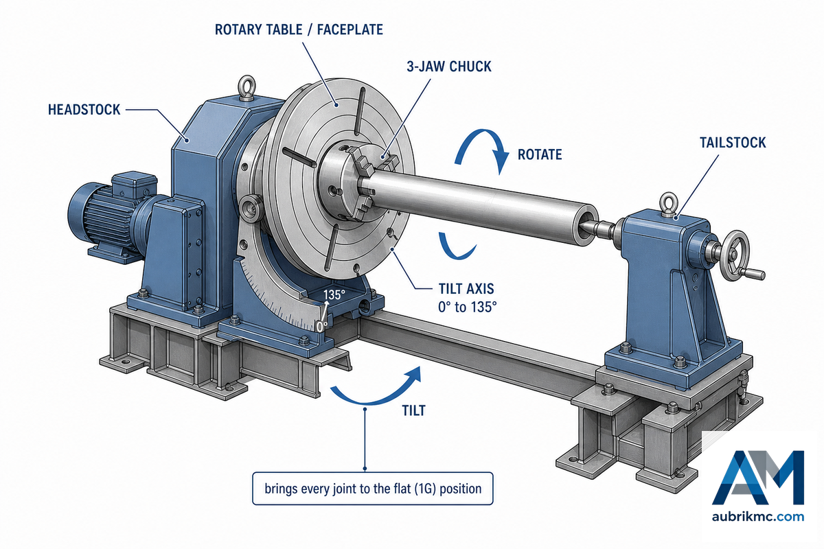
A welding positioner is an electrically operated workholding device that allows you to manually place or swing a weldment into a horizontal, flat position so you can manipulate your torch with minimum physical effort. At its heart, a welding positioner consists of a drive system, a table or faceplate, a chuck to hold the workpiece and-for long, unwieldy items-a tailstock. It does the heavy lifting for you, turning out-of-position work into downhand welding. As The Fabricator notes, a properly positioned weldment “reduces welder fatigue, increases safety, improves weld quality, and saves on production floor space.”
How does a welding positioner work?
A welding positioner clamps your workpiece to a table that spin at a controllable speed. The table is usually tilted so the weld joint can lie in a flat position beneath your stationary welding torch. The welder control the rotational speed of the part and ignites the arc, often with a foot pedal. The piece rotate uniformly under the torch, producing an even circumferential weld with far less fatigue, greater speed and cleaner results than trying to hold a torch against an overhead or vertical seam. That flat, downhand position is one of the cheapest ways to raise real arc-on time in a fabrication shop. Used this way, a positioner delivers high-quality welds with better weld consistency and far fewer weld defects, lifting productivity by giving controlled movement of the workpiece, easy access to weld joints, and an even surface for the arc on every pass—whether the job is flat or vertical welding brought down to flat.
While there are various types of welding positioners-including rotary tables, bench-top units, dual-axis machines and heavy-duty headstock-tailstock models-this guide cover operation irrespective of design. If you’re still trying to choose the right unit for your needs, our welding positioner hub page or rotary welding positioner sizing guide may be useful.
On heavy work the payoff shows up fastest. Take a pressure-vessel shop welding a 40-ton, 4 m diameter shell: on fixed stands the welder works overhead, arc-on time collapses, and every circumferential seam needs grinding and re-runs. Put that shell on a turning roll under a manipulator, tilt each joint flat, and the same seam runs downhand at full deposition—the difference between a week of rework and a clean radiograph.
Step 1: Mount and Ground It Before You Weld
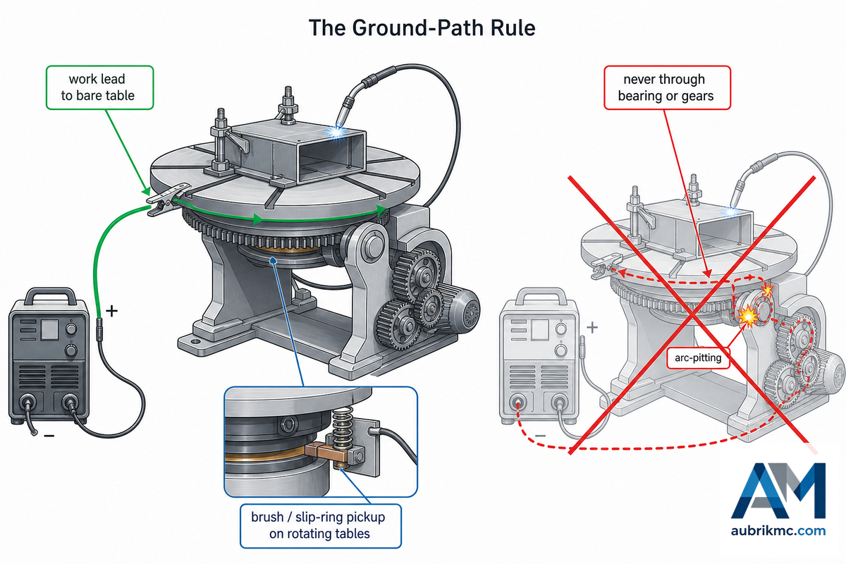
Two prerequisites must be met before switching on the power: The positioner itself must not move (unless it’s intentionally being operated), and all welding current must return directly to the welding power supply-not through the drive system’s components. Both safety and weld quality depend on fulfilling these conditions.
Bolt It. Even a small, benchtop positioner needs to be bolted to a solid, flat surface via its mounting holes, so it can’t tip when a side-loaded part or snagged cable applies unexpected force. A loose clamp, positioner-to-bench, is a catastrophe waiting for an excuse. Once it is turning, treat the positioner like any rotating machine: keep hands, sleeves, and leads clear of the table and drive, and follow OSHA 1910.212 machine-guarding practice for rotating parts, nip points, and flying sparks. In confined or semi-enclosed setups add fume extraction, because tilting a part can steer the plume straight at the operator.
The Ground-Path Rule
Here’s the single piece of information that distinguishes those who know the machine from those who quietly destroy it: The work lead must be connected to the positioner’s table or faceplate, and the welding current should never return through the bearing or the gear train. When welding current passes through a rotating bearing, it creates tiny arcs between the rolling contacts and pockmarks the races-the same sort of electric-discharge erosion that fries motor bearings on VFD-driven equipment and the drive electronics and encoder. The Fabricator plainly states the results: “If not grounded properly, electrical components can be damaged and poor-quality welds deposited.” OSHA 1910.254 demands the work lead be “firmly attached to the work”-on a positioner, the only point where you can attach it’s the table or faceplate where you clamped the part-exactly where the Fabricator says to ground.
📐 Engineering Note
Attach the ground to bare metal-scratch away paint under the lug before tightening the clamp. On continuously rotating tables, a fixed clamp would wind the work lead into a pretzel, so on industrial units, the ground typically passes through a brush or a copper block on a spring riding on the underside of the table or through a slip ring—provided that return path is solidly bonded and the collector is rated for the full weld current. Keep an eye on the ground pickup: a worn brush leads to an intermittent ground, and intermittent grounds create excessive spatter and erratic deposits before you’ll even begin to suspect the ground circuit.
Step 2: Load and Center the Workpiece
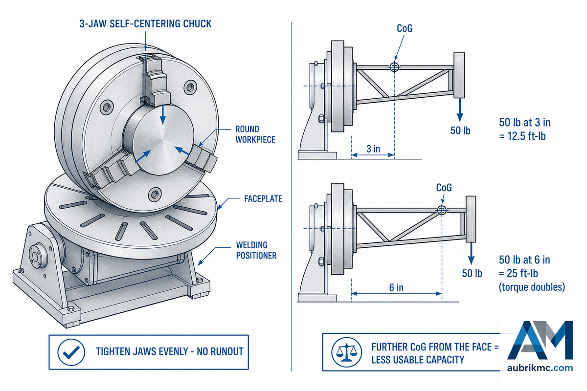
Most commonly, round workpieces mount into a welding positioner chuck—usually a three-jaw self-centering type, or an independent-jaw chuck for odd profiles; irregular shapes are mounted in a custom fixture or bolted to a positioner’s faceplate through slot holes. Center the part and uniformly tighten the chuck jaws so the work won’t wobble when it rotates-wobbling makes the torch-work distance change and causes the arc to wander. A practical word from shop personnel: The work piece may grow and shrink with temperature changes, loosening the chuck’s grip on the part; check the chuck just after tack welding.
“Selecting the right positioning device for the job involves accounting not only for the weight and size of the weldment, but also for the center of gravity and how far it is from the positioning device. As the distance increases from the device, more torque is applied to the positioner.”
This relationship is the single most important piece of information that you, the operator, need to memorize because the machine’s rated capacity is calculated on the assumption that the work piece is centered on the faceplate. If the center of gravity of the part extends past the faceplate, the usable capacity decrease sharply. Ladd’s own example: a 50-lb (23 kg) weldment held 3 inches (75 mm) off the face creates 12.5 ft-lbs of torque in the vertical position; push that center of gravity out to 6 inches (150 mm) and the torque doubles to 25 ft-lbs at the mounting surface. Double the overhang, double the load on the drive, so pieces that appear quite light can easily overwhelm a positioning device once fixtures and standoff are added.
Center-of-gravity check before you spin up
- The loaded CoG distance from the face plate with fixtures and the part shall be estimated.
- For an overhang exceeding a couple inches, you either have to downshift to the next capacity class, or make a tailstock and a steady rest to support the far end.
- Inspect the horizontal and vertical load ratings—a positioner tilted to 90° is loaded very differently from one running flat.
If you need to get a quick idea of capacity before you make your purchase, try out our welding positioner load-capacity calculator, that incorporates safety factor and an eccentric load check at your CG.
Step 3: Set Rotation Speed to Match Your Travel Speed
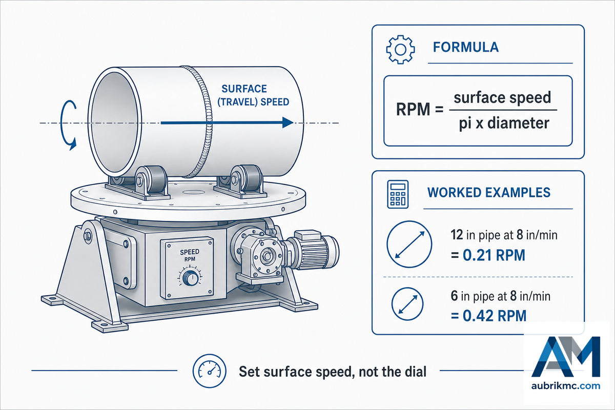
Setting the welding positioner speed is where most people get the number wrong, because the positioner dial reads RPM but a weld cares about surface speed. As a fabricator on WeldingWeb once stated, “when automating or mechanizing welding the speed is better thought of as surface inches per minute of the part.”
The Surface-Speed-First Method: 3 Steps to Set RPM
The speed to turn anything (of any diameter) is simply done in three steps:
- Choose a travel speed for your process and your joint – same ipm you would run in person.
- Measure the workpiece outside diameter at the weld.
- Convert to RPM: RPM = surface speed ÷ (π × diameter).
🔢 Worked example
you want an 8 in/min travel speed on a 12 in (300mm) OD pipe… that’s 12 * pi, or 37.7 in. you’ll need 8/37.7, or .21 rpm. you weld a 6 in (150mm) pipe at 8 in/min… that’s 6 * pi, or 18.85 in… you need 8/18.85, or .42 rpm! 2x the rpm for half the pipe… but the same length of bead.
Below is an average surface speed range for various process types along with their resulting RPM for two common diameters. Use these as guide posts, always double check your welding procedure.
| Process class / joint | Surface speed (mm/min | in/min) | RPM @ Ø300 mm | RPM @ Ø600 mm |
|---|---|---|---|
| TIG (GTAW) root pass | 40–75 | 1.5–3 | 0.04–0.08 | 0.02–0.04 |
| TIG (GTAW) fill/cap | 75–150 | 3–6 | 0.08–0.16 | 0.04–0.08 |
| MIG (GMAW) short-arc | 200–400 | 8–16 | 0.21–0.42 | 0.11–0.21 |
| MIG (GMAW) spray | 300–600 | 12–24 | 0.32–0.64 | 0.16–0.32 |
| Flux-cored (FCAW) | 250–500 | 10–20 | 0.27–0.53 | 0.13–0.27 |
| Submerged arc (SAW), single wire | 400–900 | 16–35 | 0.42–0.95 | 0.21–0.48 |
| SAW, tandem/multi-wire | 900–2,000 | 35–79 | 0.95–2.1 | 0.48–1.06 |
| Hardfacing build-up | 150–300 | 6–12 | 0.16–0.32 | 0.08–0.16 |
| Strip cladding / overlay | 100–250 | 4–10 | 0.11–0.27 | 0.05–0.13 |
| Orbital tube (Ø50 mm) | 60–200 | 2.4–8 | 0.38–1.27 rev/min at Ø50 mm | |
Surface-speed bands from typical industry practice. RPM = surface speed ÷ (π × diameter). Verify against your WPS.
As a guide, benchtop table speeds run from 0 to 2.5 RPM, heavy tables sit in the range of 0.05 to 2.0 RPM, and weld surface speeds span from around 40 mm/min (TIG root pass) to over 2,000 mm/min (tandem submerged arc). If you don’t wish to get your calculator out we can also calculate surface speed from RPM or RPM from surface speed for a given diameter on our RPM and surface-speed calculator.
Step 4: Tilt to the Flat Position and Find the Clock
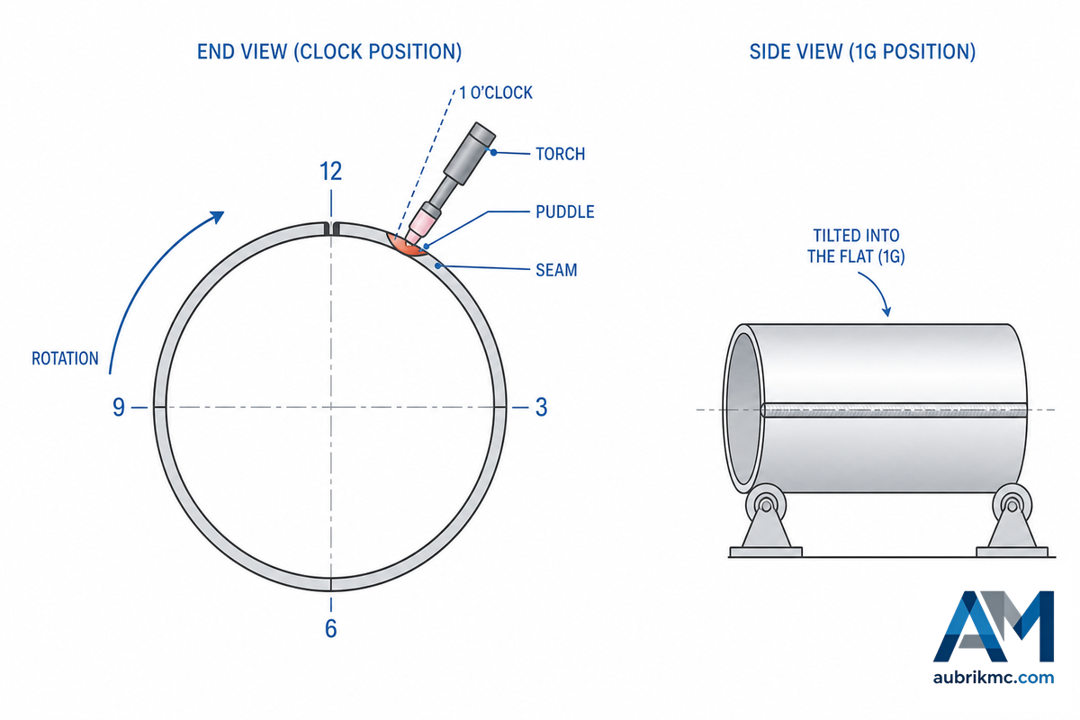
On a tilt/rotate positioner, swing the table to bring the joint to be welded in flat-the 1G position, both AWS and ISO 6947:2019 terms. The molten metal can stay where you want it because gravity is helping to keep it from flowing away. This is what causes it to produce equal fillet legs, and a smoother bead than can be made when welding out of position.
Picture a tank head run on a benchtop welding positioner with no tilt: the seam sits half-vertical, the puddle sags, and every pass shows undercut along the bottom edge while the crown piles up cold and rounded. Tilt that same joint to the flat 1G position and the defect is gone—same welder, same wire, a sounder weld with less grinding. That is the whole reason to keep bringing the active seam back to flat as the part turns.
With a rolled-out pipe or circumferential weld, torch angle is key. Typically the torch is held just up the hill from top dead center – at 1 o’clock on the pipe’s end, for instance – allowing the puddle to rest against the seam, where it cools and solidifies before slumping ahead of the arc. Move beyond that point, and you’re dragging it, then it’s chasing the puddle. Your exact clock angle depends on diameter, current, and process.
Matching the Positioner to Your Process: TIG, MIG, and SAW
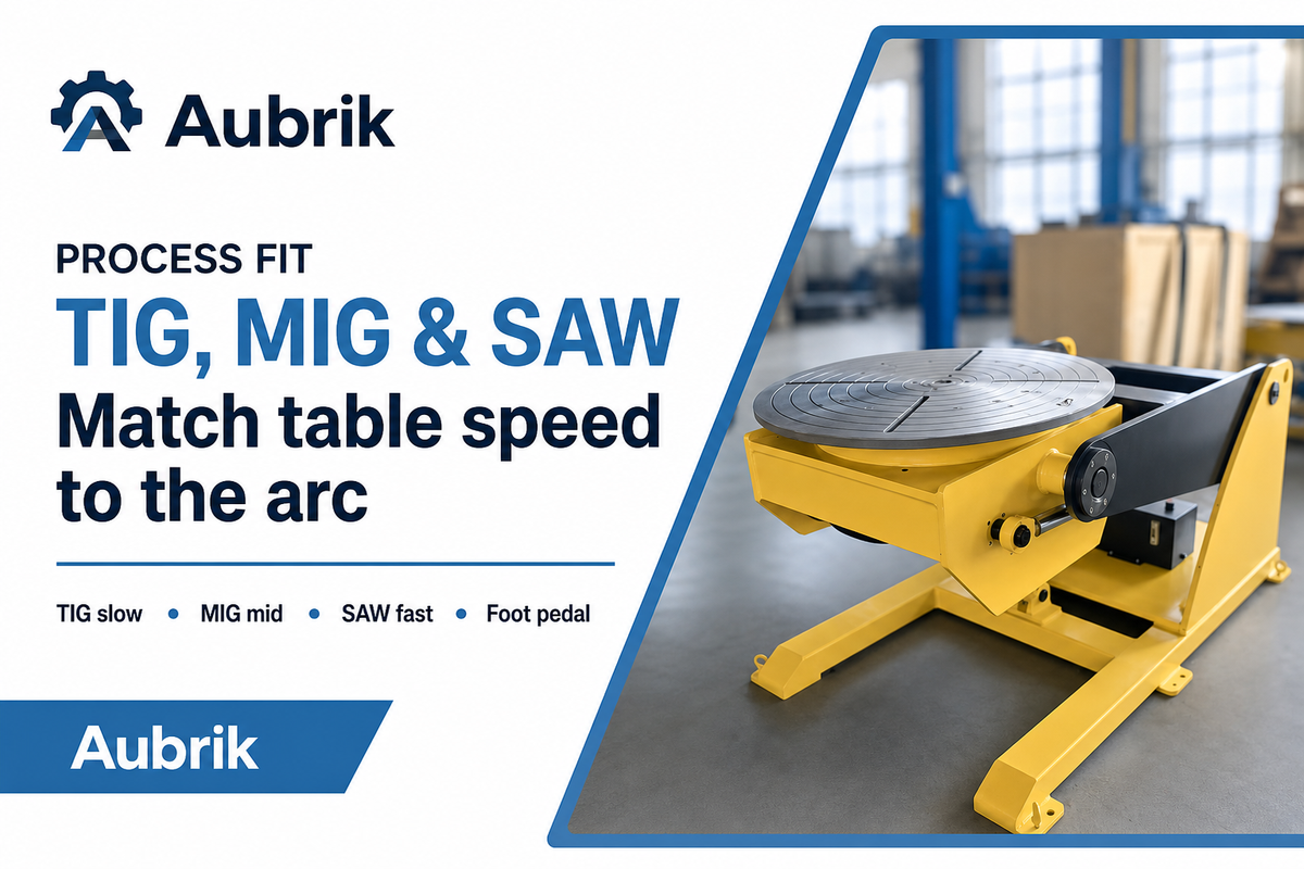
The setup procedure is universal for positioner-controlled welds, but the means by which you rotate it can differ. Two common movement patterns apply to the bulk of shop work: continuous rotation for fully circumscribed seams and index-and-weld for positioned joints that advance and then hold for the process.
Match the speed to the process, not the other way around. Run submerged arc at MIG travel speeds on a 3 mm wall tube and you punch through the root; creep along at TIG speeds under a high-deposition SAW head and you pile up a cold, ropey bead that has to be gouged out. Positioner speed has to track what the arc can actually lay down. The same positioner serves manual welding, semiautomatic welding, and automatic welding alike; matching table motion to the welding process is what turns a hand skill into a repeatable welding operation across different welding applications and welding systems.
- TIG (GTAW): A TIG welding positioner setup runs at the lowest surface speeds; match the table speed to the filler-wire feed and puddle rate. Consistency beats speed here—a steady table gives the even bead a hand-held arc struggles to hold.
- MIG/FCAW (GMAW): Moderate speeds can be attained by first triggering the puddle with a foot pedal or remote, and then starting the rotation. Benchtop positioners with variable speeds and front-and-reverse rotation are perfect for the job.
- Submerged arc (SAW): Higher speeds, higher deposit rates. the positioner’s orientation works with a torch stand or manipulator so that flux always cover the joint in its highest-pointing aspect. If it’s part of a fully integrated system, an operator can initiate the weld with a foot pedal, and the program-including pauses to let the puddle form and crater fill-plays out automatically.
A long straight seam or when the torch itself must be moved will require more than a positioner-that’s the job for a column-and-boom welding manipulator. Frequently this system is employed with the positioner within a work cell.
Positioner Mistakes: 10 Faults and Their Fixes
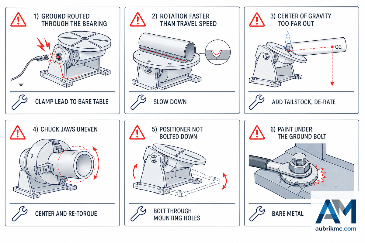
Most positioner troubles aren’t machine-related but originate with how the user set up the process. Here are the common shop floor mistakes, how much they’ll cost you and what to do about them—starting with the grounding fault, which OSHA 1910.254 treats as a work-lead requirement, not just a quality problem.
| Fault | What it ruins | Fix |
|---|---|---|
| Ground returns through the bearing/gears | Arc-pitted races, burned drive/encoder | Clamp lead to bare table; brush pickup on rotating tables |
| Rotation faster than travel speed | Undercut, rolled bead, lack of fusion | Set surface speed = weld travel speed; slow down |
| CoG far off the faceplate | Motor stall, tip-over, gear wear | Keep CoG on-axis; add tailstock; de-rate for overhang |
| Jaws not tightened evenly | Runout, wandering arc, uneven bead | Center and torque jaws equally; check runout dry |
| Grip loosens as part heats/cools | Part shifts mid-weld, scrap | Re-check chuck after tacks; allow for expansion |
| Out-of-round part, fixed torch height | Arc length and current fluctuate each rev | Use arc-voltage/CTWD control or true the part |
| Positioner not bolted down | Tips under unexpected force | Bolt through mounting holes—even benchtop units |
| Paint left under the ground bolt | High-resistance ground, spatter, poor deposit | Remove paint to bare metal before bolting |
| No start/crater dwell on a full circle | Cold lap or crater crack at closure | Program a start dwell and crater-fill overlap |
| Worn drive wheels / ground brushes | Speed drift, intermittent ground | Inspect and replace on a maintenance schedule |
One common fault bears repeating: faster is rarely better. An arc that go too fast will produce inadequate fusion. Trying to push rotation beyond the process limits is a well-documented way to generate undercut and lack of fusion; welding guides consistently note that the ceiling is the arc itself, not the positioner.
When a Positioner Isn’t the Right Tool
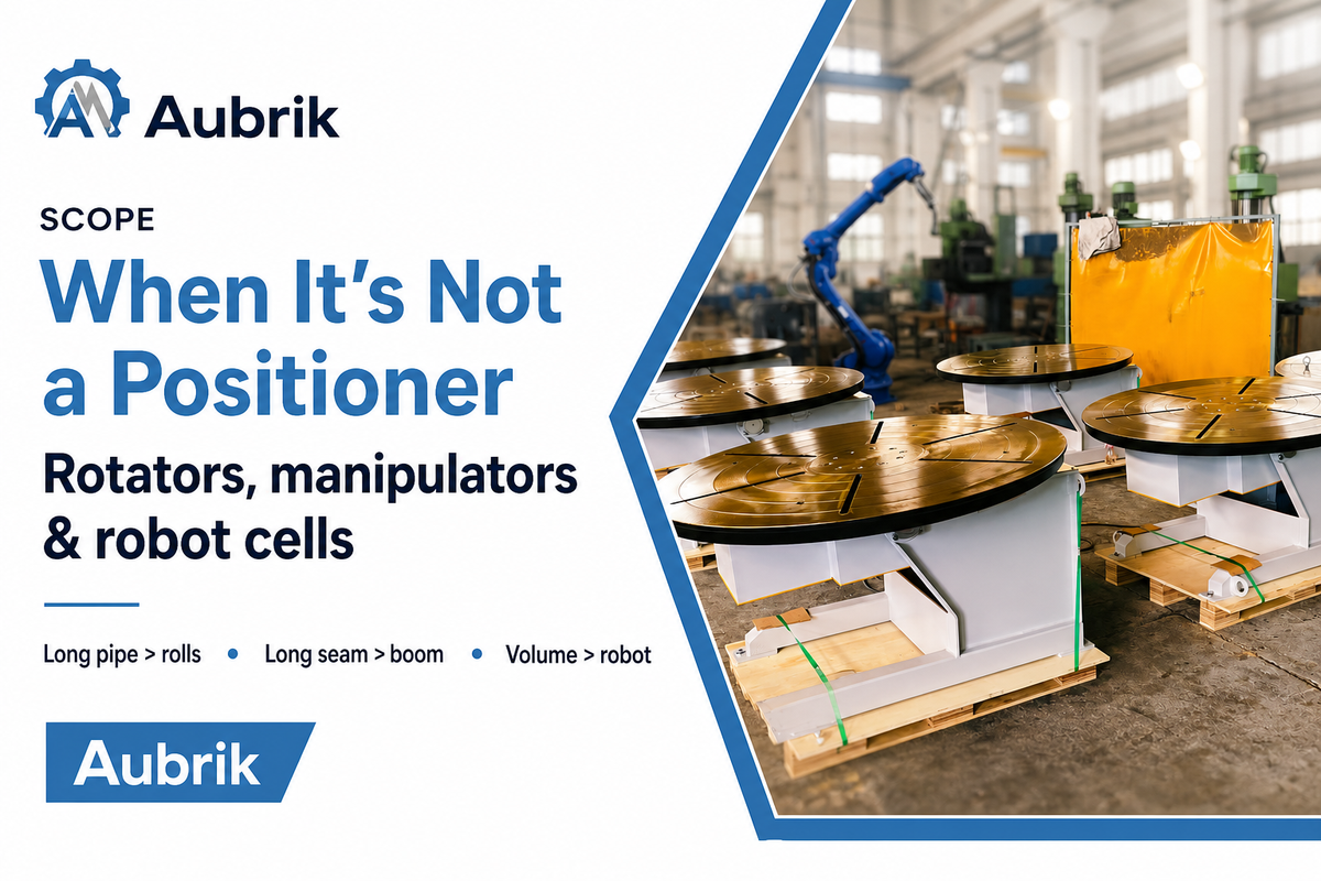
Positioners make their keep by maneuvering individual workpieces for the welding operation. That doesn’t mean they’ll solve all part-handling problems, so it’s good to note what they won’t do.
- Heavy, long pipe and cylindrical parts do better rolling along welding rotators or turning rolls that cradle the part length between two support rollers. See the pipe rotator operating guide for set-up instructions.
- A long, straight seam will need the torch to move – not the workpiece. That task require a column-and-boom manipulator or gantry.
- High-volume, identical workpieces are a good case for a robotic welding cell, where the positioner serves as the part-manipulating element within the robotic system.
Most shops implement all three: a positioner for weldments, a turning roll for cylinders, and a manipulator or cell as production increases. For matching equipment to a specific part, the heavy-duty positioner and welding turntable selection guides in our Related Articles go deeper on each type.
Why Positioner Use Is Rising in 2026
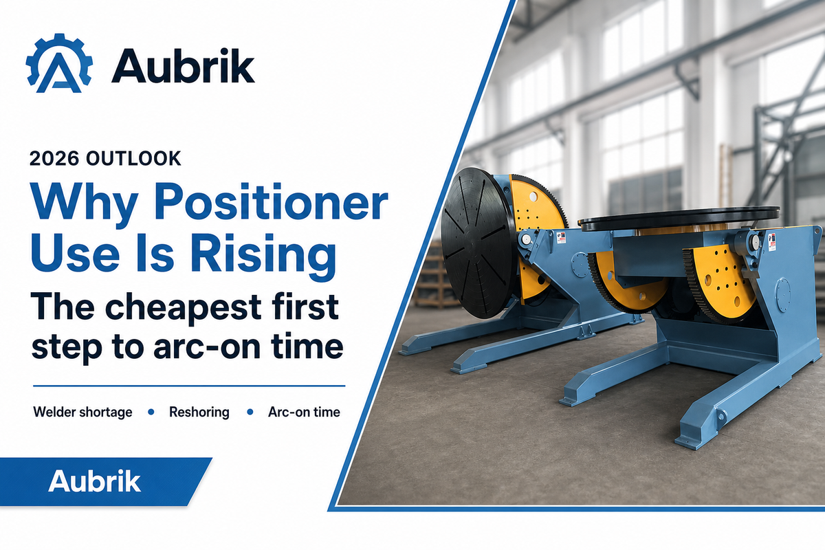
The motivation to understand positioner operation now has little to do with technology and much to do with a labor shortage. The Fabricator’s reporting on the welding workforce highlights the lack of skilled welders. Job openings for welding professionals consistently exceed the number of workers entering the field, a gap shops can’t solve by simply hiring more help. Consequently, fabricators must find ways to extract more completed welds from their existing welding workforce, and since arc-on time typically averages just 10-15% of a welding shift, moving welds to the flat position is the least expensive approach. Most shops take this first step of automation before ever considering robotic cells. But the picture is genuinely mixed: the U.S. Bureau of Labor Statistics projects only about 2% welder employment growth through 2034, and the International Federation of Robotics notes that smaller shops often lack the integrators and process design to jump straight to robots. That is exactly why the positioner matters—it is the automation step a small shop can actually take today, without a robot cell’s overhead.
This market trend is reflected in the sales data: industry analysts estimate the automated-welding sector accounts for approximately half of all arc-welding equipment sales and has grown about 5-6% annually, with robotic welding seeing even higher growth rates. However, from a buyer’s perspective, a more immediate action item involves standardizing grounding, clamping, and speed settings for your shop’s current positioners before investing in new equipment. Those operators who have mastered these three procedures will be the ones that make your investment in automation a profitable one.
FAQ: Using a Welding Positioner
How do you ground a welding positioner?
View Answer
Attach the work lead directly to the positioner’s table or faceplate, on bare metal with any paint removed under the lug, so current returns from the part and not through the bearing or gear train. On a table that rotates continuously, ground is transferred through a brush or spring-loaded copper block riding on the table back or a slip ring, because a fixed clamp would wind the cable. A poor or bearing-routed ground pits the races, burns the drive, and produces substandard welds.
What speed should a welding positioner run at?
View Answer
Set the speed by the part’s surface, not the table dial. Choose the surface (travel) speed your process wants—roughly 1.5–3 in/min for TIG root, 8–16 in/min for MIG—then convert to RPM with RPM = surface speed ÷ (π × diameter). A 12-inch pipe at 8 in/min turns at about 0.21 RPM; a 6-inch pipe at the same speed needs 0.42 RPM. Smaller diameters always need higher RPM for the same bead.
How does a welding positioner work?
View Answer
A welding positioner clamps a workpiece to a variable-speed rotating table and, on tilting models, swings that table so the weld joint sits flat. The operator sets the rotation speed and triggers the arc, usually with a foot pedal; the part then turns steadily under a fixed torch to lay an even circumferential weld while gravity holds the puddle. That flat, downhand position improves weld quality and raises arc-on time.
Can you use a welding positioner for TIG welding?
View Answer
Yes—TIG is one of the best fits, because a steady rotation holds the even travel speed hand-welding struggles to keep. Use the slow end of the speed range and match the table to your filler-feed rate.
What is the difference between a welding positioner and a welding rotator?
View Answer
A positioner grips a weldment at one point—usually a chuck or faceplate—and can both tilt and rotate it, which suits discrete parts and fixtures. A welding rotator (turning rolls) cradles a long cylinder on two sets of wheels and only spins it about its own axis, distributing weight along the length for pipes, tanks, and vessels. Choose the positioner for tilt-and-rotate flexibility, the rotator for long round work.
How do you center a workpiece in a positioner chuck?
View Answer
Seat the part against the chuck face, tighten the three self-centering jaws evenly, and spin it by hand to check for runout before striking an arc. Re-check the grip after tack welds, since heat can change the clamp.
Sourcing a positioner sized to your work?
Aubrik manufacturers a range of welding positioners, rotators and complete welding solutions-all thoroughly tested and calibrated before shipment, with frequently used spare parts readily available. Provide us with details of your workpiece, its weight and the welding process, and we’ll custom-build a machine to meet your needs.
About This Guide
This operating guide has been assembled by the Wuxi ABK Machinery (Aubrik) engineering staff using established welding-industry best practices and publications. These include information from OSHA 1910.254, AWS/ANSI Z49.1, ISO 6947:2019 and the Fabricator, as well as operational experience shared by welders on welding forums. Specific values-such as rotation speed, torch clock angle and capacity de-rates-will vary depending on the machine, wire, and joint; we acknowledge this, as optimal positioner settings can only be determined through a test weld on your part.
References & Sources
- OSHA 1910.254 — Arc Welding and Cutting — U.S. Occupational Safety and Health Administration
- OSHA 1910.212 — General Requirements for All Machines (Guarding) — U.S. Occupational Safety and Health Administration
- OSHA 1926.351 — Arc Welding and Cutting (Construction) — U.S. Occupational Safety and Health Administration
- Welding Safety Essentials (ANSI Z49.1 basis) — American Welding Society
- 5 Things Welders Need to Know About Weld Positioners — The Fabricator / The Welder (Jason Ladd, Koike Aronson)
- Putting the Spin on Benchtop Positioners for Tube and Pipe Welding — The Fabricator
- Outlook, Trends, and Pay for the Welding Workforce (AWS Data) — The Fabricator / American Welding Society
- Welders, Cutters, Solderers & Brazers — Occupational Outlook Handbook — U.S. Bureau of Labor Statistics