Get in Touch with Aubrik Company
WIND TOWER PRODUCTION LINE
Wind Tower Production Line — Turnkey 6-Stage Tower Manufacturing System
A wind tower production line is the switch that flips whether your shop produces 60 sections per year or 600 – and whether your welds come back as rework or pass third party NDT. Behind that switch, Aubrik builds the integrated, six-stage line: CNC cutting, rolling, fit-up, submerged-arc welding, NDT, and coating, delivered as one machine not one hundred that may or may not communicate well.
We have been building these for projects like onshore wind and offshore wind since 1999 to produce wind turbine tower sections with capacities from 2 MW to 8 MW and diameters up to 8.5 m. For renewable energy as it scales, each wind farm operator and tower fabricator requires a wind tower production line that maintains quality as volume increases. The engineering below reflects the tolerances, standards, and capacities. It avoids adjectives.
AUTO RUN


SPEC // MATRIX
DATA OUTPUT
±1 mm
SAW joint accuracy
+40%
productivity vs traditional lines
60–600
tower sets / year (modular)
500,000 t
steel processed / year
2–8 MW
onshore & offshore, ⌀2.5–16 m
EN 1090-2 · DNV
EXC3 + DNV-ST-0126 ready
[SYS-DIAGNOSTIC]
The Hidden Cost of a Fragmented, Manual Wind Tower Line
For most wind tower production lines, most capacity problems are fit-up and handling – not welding. At 35 in/min, your robot torch moves much faster than sections can be manipulated, loaded, clamped, and removed by hand; as a result, throughput is determined not by the arc but by manual loading times.
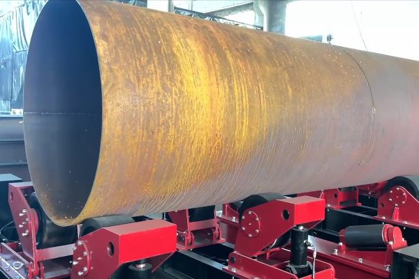
A wind tower is really just stack of tubular cylindrical rolled steel cans – coupled with longitudinal and circumferential welds – then flanged, inspected, and coated.
With manually-fed, separate machinery at each stage of these operations, there are three quiet and mounting cost centers.
[ERR-LOG // BOTTLENECKS]
01
Idle arc time.
Most manual welding work takes only 8-30% of the total machine time, so most of it – while your welders and machinery are on the clock but doing nothing useful – goes to repositioning, cleaning, and waiting.
02
Rework you find late.
One wind industry inspection firm has concluded that nearly two thirds of some 40,000 wind assets from some ten manufacturers exhibited a high risk, with a number found “to have welded over cracks, prioritizing rapid output over correct manufacture” as they rushed to meet demand.
03
The broker trap.
When fabricators outsource welding to sub-contractors because they can’t afford to maintain heavy welding machines in-house, their customers face the risk of long delays when just one of those subs trips up.
ENGINEERING SOLUTION
Integrated welding directly eliminates all three problems at their source because one machine-control logic layer both drives the weld and orchestrates movement between each stage-the engineering solution for the material bottlenecks you can plan against in advance on an Aubrik wind tower production line. Across the country, the U.S. Department of Energy counts over 500 domestic wind manufacturing sites in its wind manufacturing and supply-chain program, where competition among wind tower manufacturers in the wind energy sector turns on exactly this efficiency.
// SYSTEM_OVERVIEW
Inside the Aubrik 6-Stage Wind Tower Production Line
Where thick-plate and offshore segments are a challenge, it’s precisely the problem of fabrication efficiency and deformation control where the heat from massive welds deforms flanges faster than crews can possibly make those repairs. By subdividing the wind tower manufacturing process into six sections of machine and machine feeding closely into the next in line on strict, controlled tolerances – we build in precision and engineer for the control you need to achieve. welding automation follows your schedule, not your mistakes.
Stage-by-stage equipment
01
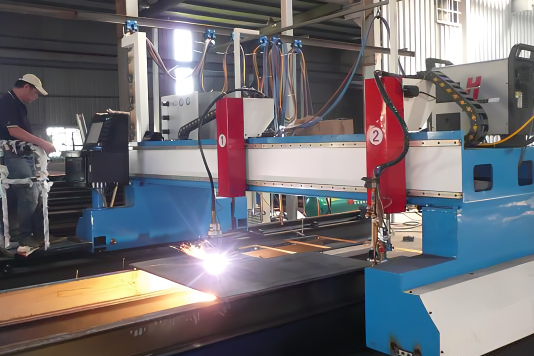
Raw-material pretreatment
CNC plasma cutting with laser positioning and real-time thickness compensation holds 1.5 mm blanking on plate up to 210 mm; shot blasting reaches ISO 8501-1 Sa 2.5 for coating adhesion.
02

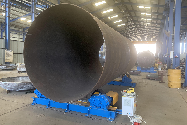
Plate rolling & forming
A CNC three-roll bending machine forms cans from 2.5 m to 16 m diameter; a laser section-alignment platform corrects deformation to 0.5 mm on the longitudinal seam.
03
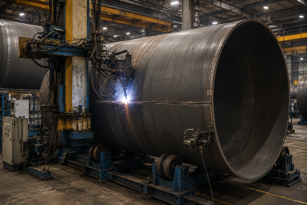
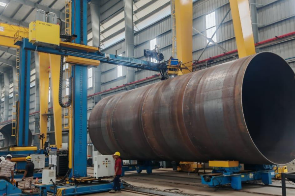
Welding
Cantilever submerged-arc welding (SAW) with robotic circumferential tracking holds 1 mm joint accuracy across multiple weld processes (SAW and FCAW). Welding positioners and rotators index each can so the seam stays in the flat position, lifting efficiency over 50% against manual work and producing high-quality, low-porosity welds.
04
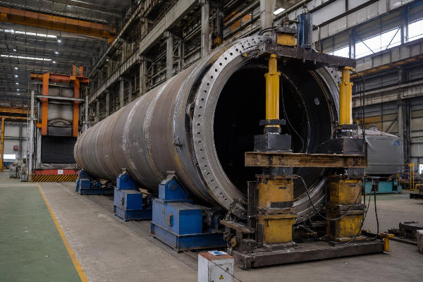
Flange assembly
A 300-ton hydraulic straightener plus post- weld heat treatment holds flange runout below 2 mm/m; CNC flange drilling positions holes to 0.5 mm.
05
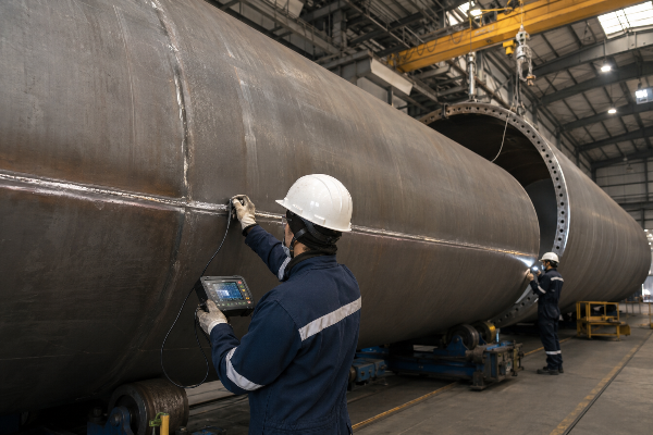
NDT & inspection
Digital ultrasonic testing (UT) to NB/T 47013.3 and ISO 17640, with visual inspection to ISO 17637, validates every weld before it moves.
06

Coating & finishing
An automatic painting turntable lays 50-200 m film to ISO 12944, with controlled drying for a 25-year service target.
// SPEC_MATRIX
Line Tolerance Stack-Up
Published tolerances only matter if you can see how they accumulate into the finished tower. Here is the accuracy budget the line holds, stage by stage – the number competitors leave blank.
| Stage | Operation | Held tolerance | Why it matters downstream |
|---|---|---|---|
| Cutting | CNC plasma blanking, ≤210 mm | ±1.5 mm | Sets can circumference; error here multiplies at roll-up |
| Forming | 3-roll bending, ⌀2.5–16 m | uniform curvature | Round cans = even root gap for the seam |
| Fit-up | Laser section alignment | ±0.5 mm/m | Clean joints let SAW run un-interrupted |
| Welding | Cantilever SAW, robotic tracking | ±1 mm joint | Full penetration, low porosity, less rework |
| Flange | Hydraulic straighten + PWHT | runout < 2 mm/m | Bolt-fatigue control — a documented collapse driver |
| Drilling | CNC multi-axis flange | ±0.5 mm hole | Tower-to-tower bolt-up without field rework |
That flange figure is not a marketing number – it is a safety chain. Heat-induced flange distortion drives bolt fatigue, which research links to in-service tower failures, so holding runout below 2 mm/m to DNV-grade limits is structural engineering, not finish.
// PARAMETERS
Engineering note — SAW parameters
automated cantilever SAW runs at 500-1200 A, 28-36 V and 30-60 cm/min with path-tracking robots, after 60°±5° bevels and a 2-4 mm root gap qualified to a written procedure under ISO 15614-1. Pre-heat sits at 80-150 C with 100-180 C interpass to stop cold cracking in high-strength thick steel, and a 600-650 C stress-relief anneal follows. Internal weld defects are then graded by ultrasonic testing to ISO 17640.
“We do not advertise a single headline number for deposition rate, because it changes with stand-off and plate thickness. What we hold to is the tolerance hand-off – if cutting drifts past 1.5 mm or fit-up past half a millimetre, the SAW head inherits the error. We tune the line so each stage protects the next.”
Honestly, even an automated line leaves residual manual scope, because internal fixtures and complex areas still require manual welding. What buyers experience as “low welding efficiency and difficult deformation control in fabrication of thick plates for offshore wind towers” is really upstream fit-up, not the arc — and the structural fix is that Aubrik engineers each station around the hand-off above, built around a measured tolerance budget. An EU buyer or regional fabricator inherits clean joints feeding the seam rather than a fast torch chasing a crooked one.
Sizing Your Line: Capacity & Cost-Per-Tower Economics
A first sizing mistake is confusing a tower-section line with a monopile foundation factory — a mismatch that risks oversizing, starving capacity, or burying the hidden cost of idle stations. Aubrik sizes a wind tower production line in tower sets per year and in steel tonnage, so you match the line to a real order book instead of a brochure throughput figure.
Sets-Per-Year Capacity Ladder
| Output tier | Configuration | Steel throughput | Best fit |
|---|---|---|---|
| 60–120 sets/yr | Single integrated line, 24 h ops, 2 sets / 3 days | up to ~150,000 t/yr | New entrant or regional supplier |
| 180–300 sets/yr | Line + duplicated welding & flange stations | ~250,000–350,000 t/yr | Established fabricator scaling onshore |
| up to 600 sets/yr | Modular workstation expansion, no production stoppage | up to 500,000 t/yr | OEM-supplier / regional wind base |
That ladder matters because you start at the bottom rung and bolt on modular workstations later without shutting the line down — the structural reason an industrial buyer scales capacity roughly 30% cheaper than a full rebuild. Aubrik engineers each tier around the same tubular steel tower geometry, built around your output target, so a regional producer building 100 a year and a 600-set OEM run identical proven stations at different counts.
Product specification range
| Specification | Range |
|---|---|
| Turbine capacity | 2 MW – 8 MW |
| Tower height | 60 m – 160 m |
| Tower diameter | 2.5 m – 16 m (max 8.5 m for 15 MW-class sections) |
| Steel plate thickness | 10 mm – 210 mm |
| Tower weight | 50 t – 5,000 t per set |
| Material | Q345, S355 low-alloy high-strength steel |
That 8.5 m capability is on-trend, not over-built. The NREL/IEA Wind Task 37 15 MW reference turbine specifies a 10 m tower base, so 8.5 m sits in the working range for today’s largest onshore and offshore towers — and the frontier is diameter, not wall thickness, which is why a 210 mm plate ceiling leaves real headroom. The diameter trend is documented in NREL’s 15 MW offshore reference turbine definition.
Cost-Per-Tower Payback Model
Line economics turn on one number competitors never publish: arc-on duty cycle. Our model below uses industry benchmark ranges rather than a single invented figure, because honest payback depends on your plate mix and local labour rate.
+40%
productivity gain vs traditional fragmented lines on Aubrik installations
Corroborated independently: a comparable automated-line case reports +40% speed, −30% labour, <2-year payback (rchelec.com). Industry payback benchmark: 18–36 months.
Arc-On duty
Manual 8 – 30% VS automated SAW 80 – 95%. This is the main driver of throughput.
Deposition Efficiency
SAW ~99%; SMAW 60-65%. For 20MM weld depth, you need 2-3 passes SAW vs 5-7 passes smaw.
Labor Structure
One Xinjiang line reduced their tower-program of 6MW units from 80 staff to 25, cutting per- unit costs by 28% whilst increasing annual volume from 320 to 550 units per year.
[PROCESS_CORE]
Welding Equipment Inside This Line
Welding is the heart of the line, with two main equipment families carrying most of the work – it is only when the machines run as discrete units rather than an integrated, Aubrik-engineered cell that a fragmented shop hits an “alignment challenge”. These have individual product pages with detailed specifications if you’re purchasing at component level, but industrial users can even insert Aubrik stations into an established supply line. Operator and system-level demands align with ISO 14732 and every weld is verified at Aubrik’s FAT prior to dispatch.
Wind Tower Welding Equipment
Column-and-boom manipulators, welding positioners, self-aligning welding rotators (weld rotators) and integrated welding lines for the longitudinal and circumferential seams of each turbine tower section. Explore the full range of wind tower welding equipment and model specifications.
Wind Tower Girth Welder
Dedicated circumferential-seam welders with laser seam tracking and flux recovery for ⌀3–8 m sections. See how automatic girth welding reaches a 99%+ NDT pass rate.
Aubrik Line vs Manual Fabrication vs Typical Imported Lines
This is not really a China-versus-Europe comparison — the heaviest wind-tower rolling is benchmarked to Italian builders, and Aubrik competes on published engineering rather than the lowest import price. What follows is the table the category avoids: specific numbers, graded against the weld-acceptance levels in ISO 5817, not Yes/No ticks.
| Dimension | Manual fabrication | Typical imported line | Aubrik integrated line |
|---|---|---|---|
| Welding accuracy | operator-dependent | rarely published | ±1 mm joint, ±0.5 mm fit-up |
| Arc-on duty cycle | 8–30% | varies | 80–95% (automated SAW) |
| Named weld/NDT standards | shop-level | logos only | EN 1090-2 EXC3 · ISO 17640 · DNV-ST-0126 |
| Annual capacity | low, labour-bound | static figure | 60–600 sets/yr, modular |
| Named OEM clients | — | unnamed “partners” | Vestas, Siemens-Gamesa, GE, Goldwind |
| Support model | in-house only | agent / ticket relay | 48 h on-site, turnkey commissioning |
[DATA-PROOF] CREDIBILITY METRICS
Proven on the World’s Wind Lines
Most rivals’ best social proof is three client names with no numbers – the credibility gap a new supplier has to close. Aubrik answers with named tier-1 OEMs and the production figures behind each relationship, the structural reason a risk-averse EU buyer or regional developer can shortlist an Aubrik factory it has not yet audited.
Case Study: Inner Mongolia 400 MW Programme (130 Sets)
88%
Prior Weld Qualification
99.2%
Aubrik Weld Qualification
*Moved to a 4 lift with 90% lower rework. That pattern repeats at section level.
SYS-01
Vestas
An 8-year partnership supplying three customised offshore production lines.
SYS-02
CS Wind America
A line supporting roughly 600 towers per year.
SYS-03
Dajin Offshore Heavy Industry
Large offshore tower and foundation output with a 40% efficiency increase and 25% cost reduction; Dajin’s own 2024 shipments exceeded 110,000 tonnes.
SYS-04
Siemens-Gamesa, GE, Goldwind
OEM-grade towers matched to each manufacturer’s design standards.
[TECH-SPEC]
That a tier-1 OEM such as Siemens Gamesa was still filing section-alignment patents in 2024 (EP4303430A1) shows how much fit-up accuracy still decides tower quality across the industry.
[DOC-REF: AUBRIK-PROCUREMENT]
Procurement Guide: Lead Time, Capacity Tiers & After-Sales
Buyers rarely leave a supplier over price – they leave over support, after sending three emails for one vague update. The structural reason is that an industrial buyer carries the project risk, so Aubrik structures procurement around the failure modes that wreck wind projects: opaque lead time, orphaned parts and broker-style overbooking for a regional fabricator far from the factory.
How an Aubrik line quotation is built
01
[SYS-01: CAPACITY]
Capacity tier configuration indicative lead-time band sizing drives the quote, not a flat catalogue number. Request a lead-time estimate against your target sets/yr.
02
[SYS-02: TESTING]
FAT before it ships factory acceptance testing on load, precision and weld performance, with a witnessed report, so the line is proven before transport.
03
[SYS-03: DEPLOYMENT]
Turnkey commissioning: project management, installation, commissioning and operator training with an on-site response within 48 hours via a global network.
04
[SYS-04: SUPPORT]
Warranty & spares: one-year warranty, with spare parts stocked in warehouses at several locations and software updates. OEM customisation for your specifications.
RISK ASSESSMENT: AGENT VS DIRECT
Compare to a purchased, imported line from an agent: 60-110 days from spec to site; field engineers replaced by relayed tickets because lower-tier suppliers rely on WhatsApp + time-zone-delayed support; a controller that requires on arrival rewiring when voltage, e.g. 480V / 60Hz, never had been confirmed.
It is the 6-stage, integrated line that constitutes self procurement – as there is no sub-contractors yard for your schedule to get “stuck”. Aubrik’s QM also follows ISO 9001, the QMS framework governing documentation and traceability throughout your construction process.
Wind Tower Production Line Optimization Tools
cost per tower roi calculator
Evaluate your equipment investment and operational costs. Accurately calculate the return on investment for each wind tower produced.
Open Calculator Tool
line capacity sizer
Determine the optimal equipment configuration for your plant. Strategically size your production line to meet targeted annual output requirements.
Open Capacity Sizer
standards stage compliance checklist
Ensure your manufacturing process aligns with industry standards. Systematically verify compliance at every critical stage of production.
Open Checklist Tool
What is a wind tower production line?
CNC cutting, shot blasting, plate rolling, fit-up, submerged-arc welding, flange machining, NDT and coating — together, those six Aubrik stations form one calibrated line that turns steel plate into a finished tower section.
What are the types of wind tower production lines?
Most commonly they are grouped by core function: cutting and preparation; plate rolling and forming; welding (both longitudinal and circumferential); flange and ring machining; and coating and finishing. These map to the fabrication requirements for wind towers set out in EN 1090-2 and DNV-ST-0126; Aubrik supplies the complete system, rather than components assembled from diverse sub-contractors with the resulting delays and handling inefficiencies.
What standards must a wind tower production line meet?
For European and most international tenders, the tower shell is fabricated to EN 1090-2 execution class EXC3 with CE marking, because wind towers are fatigue-loaded structures rather than static ones. Welds are qualified under ISO 15614-1, then inspected by ultrasonic testing to ISO 17640 and visual testing to ISO 17637. Surface preparation follows ISO 8501-1 Sa 2.5 and the coating system follows ISO 12944, while the complete support structure is designed and certified to DNV-ST-0126. Each standard maps to a specific production stage, so an auditor can trace any weld back to the procedure that governs it.
Can the line be integrated into existing equipment?
Yes. The line is built to allow addition of Aubrik welding, flange or NDT stations to existing facilities or integration of additional modules, potentially taking a single line up to 600 sets per year without production stoppages. We will ascertain voltage, footprints and interfaces during the RFQ process so there is no surprise rewiring on site.
Which tower specifications can it process?
Towers for 2-8 MW turbines, 60-160 m tall, 2.5-16 m in diameter (up to 8.5 m for 15 MW-class sections), in 10-210 mm Q345 or S355 plate, from 50 t to 5,000 t per set. Both onshore and offshore configurations are supported.
How long are installation and commissioning?
Lead time is quoted against your capacity tier, and the line is factory-acceptance tested before shipping. Installation, commissioning and training are turnkey, with 48-hour on-site response.
How is weld quality controlled?
Welding parameters (current, voltage, travel speed) are monitored and logged for traceability, then every weld is checked by ultrasonic testing for internal defects and visual inspection for surface defects, with dye-penetrant and radiographic testing on critical welds. Defects at or above φ2 mm are recorded, repaired and re-inspected.
How much does it cost to build a wind tower production line?
Price scales with capacity tier, automation level and certification scope, so a single integrated line and a 600-set/yr expansion sit far apart. We publish the cost factors openly and quote against your specification – contact Aubrik for a detailed quotation.