Get in Touch with Aubrik Company
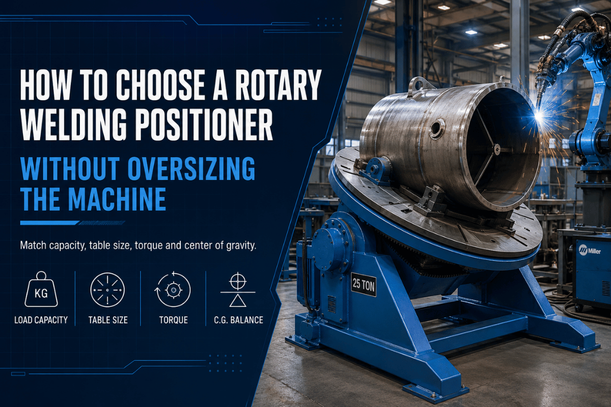
A Rotary Welding Positioner can make a weld easier to reach, but the best machine is not always the largest one on the quote sheet. Start with the part: weight, diameter, fixture mass, center of gravity, chuck fit, and the welding process.
That order matters because a weld positioner is a work-holding machine, not just a rotating table. For example, a 200 kg part with an off-center fixture can ask more from the drive and tilt frame than a round 300 kg part with a balanced load.
Flat flanges often need a different holder than short pipe sections. In TIG cells, low-speed control can matter more than the steady rotation used for many MIG repair jobs.
Quick Specs to Gather Before You Ask for a Quote
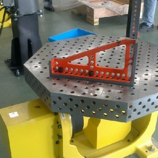
| Part weight | Include fixture, bolts, chuck, and any offset bracket, not only the raw workpiece. |
| Diameter and weld path | Record outside diameter, weld location, and whether the torch must reach the inner or outer side. |
| Rotation need | Note if the part needs 360 rotation, tilt angle changes, horizontal access, or vertical access. |
| Process | TIG, MIG, manual welding positioners, semi-automated torch stations, and fixture-ready cells all need different control habits. |
Start With the Workpiece, Not the Weld Positioner Name
A positioner work plan should begin on the shop floor, not in the catalog. Put the workpiece on paper first: actual kg or lbs, fixture weight, expected weld position, material thickness, outside diameter, and how the operator or welding torch will approach the joint.
Welders may want the joint kept in a comfortable flat or near-flat position. Welding engineers may want repeatability and precision from one batch to the next. Buyers may want one adjustable unit for several welding applications.
These are different needs, even if they all point to rotary welding equipment.
Aubrik engineering review note: treat the fixture as part of the load.
Lathe chuck weight, adapter plate thickness, 3-jaw set mass, and offset brackets can change the machine choice before the workpiece itself reaches the table.
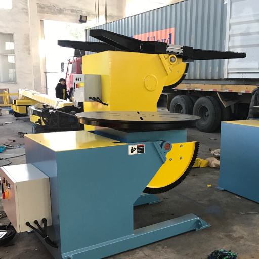
For buyers already looking at Aubrik, the current rotary welding positioner line lists 9 models and covers 50-5000 kg capacity, with CE and ISO 9001 references on the product page.
That range is useful for first filtering, but it should not replace a load sketch. From that sketch, the engineer can see where the center of gravity sits and whether the part can rotate without striking the base, the floor, or the operator area.
What numbers belong on the first sketch?
The first sketch should show the measured load in kg or lbs, the outside diameter in mm, the fixture plate thickness in mm, and the offset distance in mm. If those values are not ready, model selection turns into guesswork.
Safety also belongs in this early sketch. OSHA 1910.252 covers general welding, cutting, and brazing requirements, including fire prevention, protection of personnel, and safe handling of welding equipment. Its hot-work precautions include a 35-foot (10.7 m) combustible-material reference distance in several fire-watch conditions. Positioners do not remove those duties; they change where sparks, cables, fume capture, and operator clearance need to be planned.
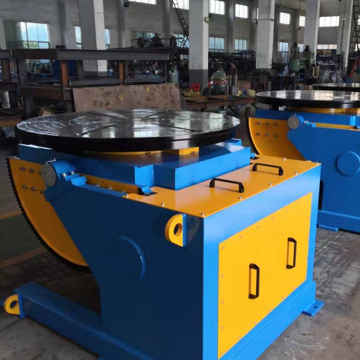
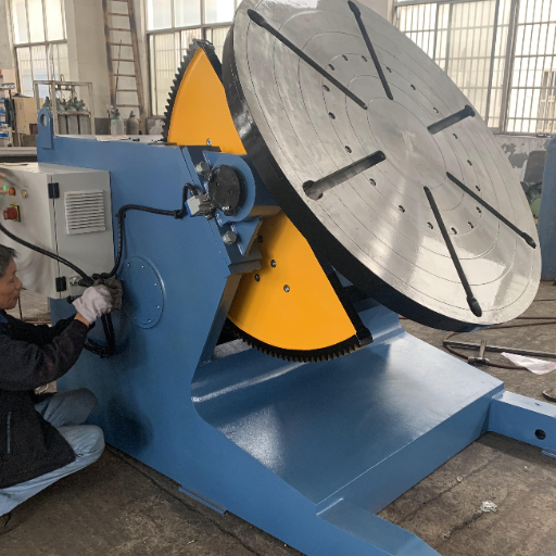
Positioner, Turntable, Rotator, or Manipulator: Which One Fits the Work?
Related machines can look similar in a quick product search. This matrix keeps the buying lane clear, which also helps avoid sending every question to the same quote form.
| Equipment | Best-fit job | Watch point | Aubrik path |
|---|---|---|---|
| Rotary welding positioner | Controlled rotation and tilt for small bench parts through heavy duty welding jobs. | Match load, diameter, table, chuck, and tilt angle together. | compare Aubrik rotary welding positioner models |
| Welding turntable or rotary table | Flat-table rotation for circular welds, small flanges, and lighter metalworking tasks. | Turntables may not give enough angle access for odd-shaped parts. | check rpm and surface speed |
| Pipe welding rotator | Long pipe, vessel shells, and cylindrical work supported by rollers. | Rotators support length; positioners control shorter parts around a table or chuck. | compare rotator vs positioner |
| Welding manipulator | Torch travel around large parts, columns, booms, and welding cells. | It moves the torch; it does not replace the need to hold and rotate the workpiece. | review column and boom options |
This article should help you choose the machine family and prepare a cleaner RFQ. Exact product comparison belongs on Aubrik’s product pages for welding positioners, welding rotators and turning rolls, and related equipment.
Load-RPM-Chuck Fit Matrix for Rotary Welding Positioner Sizing
Please refer to this Load-RPM-Chuck Fit Matrix prior to request for price quotation. This document serves as a pre-quote guideline and should not be interpreted as an engineering analysis. The values below should be considered load class reference and decision-making guide, but final model selection will still depend on detailed part sketch, duty cycle requirements, fixture design and specification, process considerations, and the evaluation of interference through the full path of rotation.
Which sample values help the supplier size the unit?
Use the following sample format to prepare measured values for a quote. These numbers are examples of the type of data to send; replace them with your own part data before asking for model selection.
| Measurement field | Sample value format | Why Aubrik needs it |
|---|---|---|
| Part mass | 80 kg | Separates raw workpiece load from the full fixture stack. |
| Fixture mass | 25 kg | Prevents the adapter from being left out of the load check. |
| Outside diameter | 220 mm | Checks table clearance and chuck reach. |
| Bolt circle | 180 mm | Shows whether a slotted table or adapter plate is needed. |
| Adapter plate | 12 mm | Adds thickness and mass between the part and table. |
| Offset from center | 40 mm | Flags a tilt-load issue before the quote is written. |
| Torch clearance | 50 mm | Keeps the fixture from blocking the welding torch. |
| Speed check | 2 rpm to 20 rpm | Frames the control question without assuming one universal speed. |
If the station uses powered controls or a mounted torch, add sample fields for 110 V, 220 V, 0.75 kW, 1.5 kW, 2 m cable reach, 25 mm clamp height, 8 mm plate thickness, and 6 month service-review timing. These are input-field examples, not promised machine ratings.
| Workpiece type | Load class | Diameter / fixture issue | Chuck or table need | RPM control issue | Welding process fit | Buyer action |
|---|---|---|---|---|---|---|
| Small round TIG parts | 50kg starter class | 200mm-class parts may still need a centered adapter. | Small 3-jaw chuck or flat table with slots. | Smooth low-speed control, often around a 2-20 rpm spec band. | TIG welding and precision circular welds. | Send diameter, torch angle, and expected bead length. |
| Pipe elbows | Light to medium | Offset shape can shift the center of gravity. | Self-centering chuck or custom jaw set. | Variable speed helps keep travel steady through angle changes. | TIG, MIG, and repair work. | Show the elbow orientation and fixture weight. |
| Short pipe sections | Medium | Large outside diameter may need clearance more than raw capacity. | Lathe chuck or pipe fixture. | Check speed range against surface travel, not only rpm. | Manual or semi-automated seam welds. | Use Aubrik’s rpm surface-speed calculator. |
| Flange assemblies | Light to heavy | Bolt hole pattern affects adapter-plate design. | Slotted welding table or bolt-on adapter. | Stable start/stop matters near tack welds. | MIG, TIG, and batch fabrication. | Send bolt circle, OD, ID, and fixture mass. |
| Tank nozzles | Medium to heavy | Nozzle offset can create high tilt load. | Custom fixture with guarded clearance. | Speed change may be needed near local thickness changes. | Pressure-vessel fabrication and repair. | Ask for a capacity check with fixture drawing. |
| Frame components | Medium | Irregular geometry may hit the base during rotation. | Fixture plate, clamps, and stop blocks. | Jog control may matter more than continuous rpm. | Manual welding and tack-to-finish work. | Send a clearance sketch from two views. |
| Heavy cylindrical fabrications | Heavy duty | Diameter and face load may be more limiting than scale weight. | Large table, custom fixture, or move to turning rolls. | Drive torque and braking feel matter during tilt. | SAW support cells, MIG, or mixed process work. | Check heavy-duty welding positioner choices. |
| Repair-shop mixed parts | Light to medium | Daily part mix can make fixed fixtures frustrating. | Accessory plate, movable cart, and changeable chuck. | Manual speed knob and foot control may help. | MIG repair, TIG touch-up, and small-batch jobs. | List the three most common parts, not every rare job. |
| Semi-automated torch setups | Sized by station plan | Torch mount, fume capture, and cable sweep define the work envelope. | Fixture-ready table, chuck, and repeatable stops. | Repeatability and compatible controls beat peak speed. | Automatic welding positioner cells and robot-adjacent stations. | Review with robotic welding system planning. |
Matching TIG, MIG, and Semi-Automated Welding to Positioner Specs
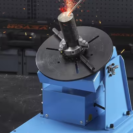
TIG operations tend to highlight issues with equipment operation. The low-end performance characteristics of positioners (smoothness of low-speed travel, controllability via hand or foot switch and cleanliness of access to part/operation) will be a stronger requirement, especially for smaller and clean parts where operator sees every speed change.
For MIG operations, some of travel motion characteristics of a positioner will be less critical but ability to retain the part without slipping remains extremely important. In some instances a poor jaw grip (on the Chuck or other workholding) or even a poorly designed table slot pattern missing the adapter-plate or a fixture hindering shielding gas flow will prove more of an issue than any shortcoming in a power source or welding station design.
Where should fume extraction sit in the station plan?
Adding semi-automated welding process involves yet another consideration: Repeatability. Semi-automated stations incorporate the welding positioner, torch, cables, hood, and operator walkway as a single work station. CDC/NIOSH notes that welding produces fumes from the base metal, filler metal, and flux that may need evacuation, and HSE guidance tells shop operators to prevent or minimize exposure. This implies ventilation must occur at the point of operation (not just on the equipment stand).
Engineering Note: Process Fit Checks
When discussing TIG welding needs, clarify the motion of the positioner at low speed and the manner of torch angle control. In MIG welding scenarios, confirm how the fixture will withstand start-stop forces and address spatter cleanup. For semi-automated cell applications, verify that the positioner motion complements torch travel and fume extraction systems.
AWS Z49.1:2021 “Safety in Welding, Cutting, and Allied Processes” establishes guidelines for safely operating welding and cutting equipment and that the choice of a welding positioner should be considered part of this safety framework especially as it relates to cable routing, heavy loads, open flame, and the effective use of exhaust ventilation systems.
Benchtop, Precision, and Heavy-Shop Sizing Mistakes
When selecting a welding positioner, an incorrect choice typically isn’t evident in the initial product specification but will be realized during the first trial-fit when a component can’t be tilted with clearance or is obstructed by fixturing when the torch is lowered. Improved access will benefit welding quality but does not alone ensure high-quality results where parameters and skill are critical, especially the control over clamping movement of table.
- Focusing on the listed rated load is common and important. However this capacity value serves only as a starting point for discussions.
- Don’t overlook the added stresses of an off-center load and of fixture weight, a heavy fixture mounted at the edge of the welding diameter will contribute as much (or more) than the part to the load seen by the table’s internal gear mechanism.
- Make certain that the welding positioner chuck selection is appropriate. Many fixtures use three-jaw chucks, but there are numerous situations that call for a self-centering chuck or special hardened jaw set with special forms and dimensions that will not work with a standard chuck design.
- Consider accessibility around the work area: In a horizontal as well as vertical welding configuration, access must be considered for torch positioner, hoses/cables, fumes extraction and for operators who have a role to play.
- Avoid using a small, desktop unit for tasks that are better handled with heavy duty, fabrication-rated welding equipment. Many lighter units are very satisfactory for non-production type applications or light welding jobs but will not sustain a production duty cycle over time.
If you’ve got the part and fixture numbers, then it’s often useful to start with Aubrik’s load-capacity calculator. If you still find yourself trying to decide between machine families, then consider the positioner selector to help differentiate a weld positioner from a rotator or manipulator.
Even a good DIY positioner kit is better to serve as a resource for hobby-level welding equipment, but these aren’t a driving force for industrial purchases when duty cycle, guard clearance, and fixture service are core elements.
What to Prepare Before Asking Aubrik for a Quote
A brief RFQ packet can prevent wasted hours of email correspondence. Send not only a product number, but a product number along with photos, not just an example product title. With this, an Aubrik positioner vendor can match one of their positioners for sale to your intended job instead of trying to surmise a match based on a single text line.
Which capacity facts are already known?
Aubrik’s current rotary positioner page lists a 50 kg lower model class and a 5000 kg upper capacity class, while user-provided company notes list 1,000 welding-equipment sets and 200 cutting-equipment sets of annual capacity. Use those values as company and product-range context, then send your own measured part data for final model selection.
Founded in 1999 as Wuxi ABK Machinery, Aubrik currently holds ISO9001 and CE certifications. User notes at the company indicate an experience-driven research and development team, annual production volumes for 1,000 sets of welding and 200 sets of cutting equipment, OEM service availability and a one-year warranty. These characteristics make for valuable starting point for customizing when either the fixture, controls, delivery time or any other requirement go beyond an off-the-shelf catalog item selection.
| RFQ item | What to send | Why it affects model choice |
|---|---|---|
| Weight | Part weight, fixture weight, chuck weight, and offset distance. | Capacity and tilt load are not the same problem. |
| Geometry | Diameter, length, weld location, and a photo or sketch. | Clearance can rule out a table size before capacity does. |
| Process | TIG, MIG, SAW support, manual, or semi-automated station. | Speed control, torque feel, and torch access change by process. |
| Fixture | Flat table, lathe chuck, 3-jaw chuck, self-centering chuck, or custom adapter. | Fixture mass can become the largest source of hidden load. |
| Controls | Voltage preference, speed control need, foot switch, and integration notes. | Control style affects operator rhythm and station layout. |
| Shop context | One-off repair, batch fabrication, production cell, or mixed job shop. | Similar loads may need different duty and accessory choices. |
When those documents are available for your intended purpose, then it becomes much easier to transition from the guide to a given product page and request the correct welding positioner.
How Buying Is Shifting Toward Fixture-Ready, Process-Ready Systems
For many buyers, welding positioners and accessories have evolved into station accessories instead of the individual tools that they once were. On a workcell station, each positioner works with the welding torch, fumes extraction system, power supply, robot or carriage, operator travel routes and the manner by which the workpiece is loaded into the cell.
As of 2024, the International Federation of Robotics (IFR) has confirmed the placement of 542,000 industrial robots throughout factories across the globe. More than twice this number was present at factories just ten years ago and this is the fourth consecutive year in which new installations have exceeded a half-million units. Naturally, these figures don’t translate into a need for robots in every workshop, however, the reality does mean that shops are making increasingly thorough, process-orientated inquiries prior to purchasing new equipment destined for their welding cells.
For example, the questions asked about a rotary positioner include: Is it feasible to accommodate the fixture on the table? Will the chosen chuck be able to handle this part range? Can the welding torch be maintained steady while the weld job is being rotated within the stable position? Is there enough operational clearance for the cables, extracted air and the individual working the machine? Will the welding station necessitate repeatable position stops or would a manually adjustable system suffice?
The concept of automation frequently resurfaces in the welding market by revisiting essential shop floor metrics: reduced inconvenient resets, the realization of consistent welding motion speed, enhancement of station productivity and a decrease of unproductive intervals between parts. Even then, ultimate achievement still hinges upon both the plan for the process and the design of the fixture, not solely the welding positioner itself.
FAQ
How does a welding positioner work?
During operations, the welding positioner physically supports the workpiece via its table, chuck, or fixture in a specific configuration (forwards, backward, or side-to-side) for access to the weld joint from the most suitable welding viewing angle. However, an operator still ultimately manages quality assurance, joint fit, heat input and security checks.
Can one rotary welding positioner support both TIG and MIG welding?
One rotary positioner can indeed accommodate TIG and MIG work simultaneously, but this requires compatible setup options to enable both welding methods; this usually means smoother low-speed rotation and simpler torch accessibility for TIG applications and more emphasis on fixture gripping, spatter clearance and cable management for MIG jobs.
How much capacity should a welding positioner have?
Select the capacity after your part, fixture, chuck, adapter plate and offset load have been added to the welding chuck. A perfectly balanced, 300kg part will strain the tilt mechanism and drive considerably less than an off-center 300kg assembly.
Do I need a 3-jaw chuck or a flat welding table?
Round parts are best centered with a 3-jaw chuck on a table or fixture. Flat welding parts with cutouts can hold a bracket or fixture. It’s very common in an industrial setting for an adapter plate to be mounted between your workpiece and table positioner.
What is the difference between a welding positioner and a welding rotator?
When shorter parts are held by a chuck or table chuck on a headstock and tailstock-style welding positioner, tilt and rotation are controlled. Since rollers support longer, cylindrical parts such as pipes, shells and tanks, welding rotators are common for these applications.
When should I choose a heavy duty welding positioner instead of a small bench unit?
For large parts and fixtures, especially when an off-center, repetitious shop environment calls for increased table capability to operate with a heavy load, choose an industrial welding positioner rather than small desktop devices that were intended to handle lighter weights and simpler tasks.
References and Sources
- OSHA 1910.252 – General requirements for welding, cutting and brazing
- CDC/NIOSH Engineering Controls Database – Welding Operations: Local Exhaust Ventilation Systems
- HSE – Welding fume: protect your workers
- AWS Z49.1:2021 – Safety in Welding, Cutting, and Allied Processes
- International Federation of Robotics – World Robotics 2025 industrial robot press release