Get in Touch with Aubrik Company

How to Plan a Steel Structure Workshop for H-Beam Flow

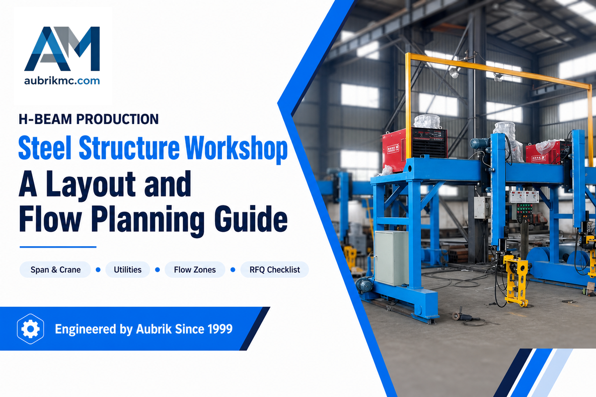
A Steel Structure Workshop is a production facility that works best when its building, cranes, machines, utilities, and material routes are planned as one system. Start with the H-beam you need to make and the sequence it must follow. Only then should you freeze the span, column grid, crane runways, foundations, and equipment positions.
This guide focuses on production layout rather than the building shell alone. Planning a workshop building isn’t the same as planning a generic warehouse or choosing a prefab shell: the steel frame must support a defined manufacturing flow. If you’re already comparing complete equipment and building configurations, review Aubrik’s Steel Structure Workshop solution. Sections below help you prepare the process data that makes that conversation productive.
By Wuxi ABK Machinery Co., Ltd. · Updated July 2026
Quick Specs for the Planning Brief
- Product data — member type, grade, maximum length, maximum section, and heaviest lift
- Production data — annual output, shifts, product mix, process cycle times, and changeovers
- Handling data — crane reach, hook height, forklifts, roller transfers, and exception routes
- Facility data — available length and width, floor loads, doors, exits, utilities, extraction, and expansion boundary
- Quality data — inspection stages, nondestructive testing access, hold points, records, and acceptance criteria
1. Start With the Production Problem, Not the Building Shell
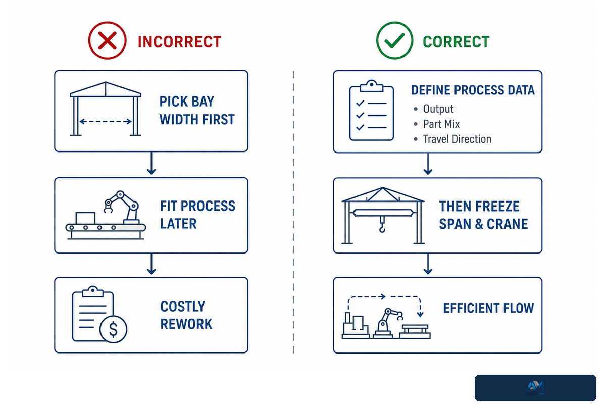
A workshop floor plan should start with output, part mix, and direction of travel since these define the repeated flow across the plant. An empty bay with huge space can be inefficient if it has cross traffic, cannot hand off material to a crane, or requires a finished beam to reverse against the fresh raw-stock flow. A shell supports the process; it doesn’t dictate the process.
Create a list: annual tonnage or pieces, number of shifts, range of plate and beam sizes, longest member, heaviest sub-assembly, the way material arrives to the dock, the way finished goods are loaded, and mandatory inspection points. These items form a common language for the process engineer, the machine builder, crane supplier, structural designer, safety team, and the general contractor.
Common planning mistake
A buyer selects a nominal bay width first and asks the production line to fit later. That reverses the dependency. Part routes, lifting points, machine service envelopes, and protected exits should challenge the initial bay concept before foundations and runway columns become expensive to change.
Separate the layout guideline article from a product specification. A decision aid briefly describes the data driving the layout, and the H-beam steel structure production line page describes a selected family of processes.
2. Map the Five-Stage H-Beam Production Flow
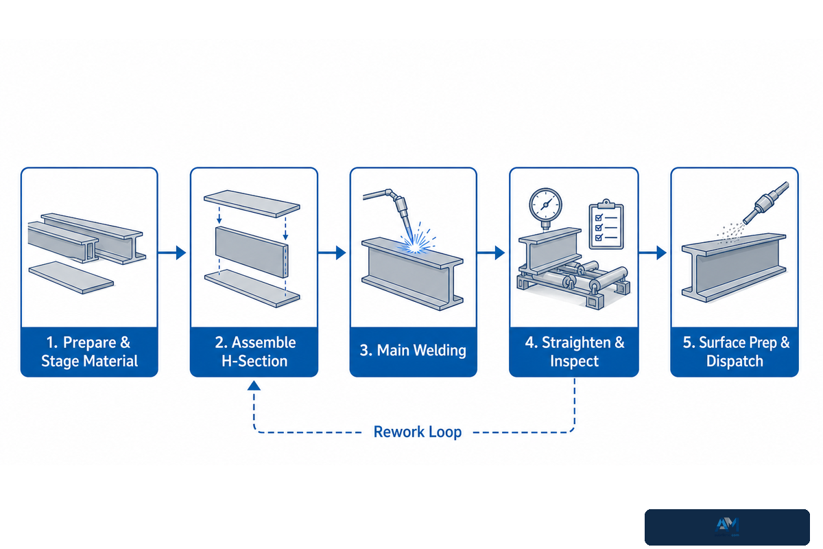
A typical welded H-beam sequence often includes plate preparation, fitting, main weld, straightening/correction, and painting or other surface preparation, followed by shipping. Each machine’s description will vary but there should be an obvious preferred direction for the material to travel. Rework, holds, maintenance or odd-length members need contained loops with side paths, not an accidental reversal of flow.
- Prepare and stage material — receive plate, identify grades and heat numbers where required, cut components, and stage matched webs and flanges without blocking the main route.
- Assemble the H section — align the web and flanges, tack or secure the fit-up, and leave enough loading and service space around the H-beam assembly machine.
- Complete the main welding — transfer the member to the submerged arc welding station, provide gantry travel and cable or flux routes, and keep fume controls compatible with movement.
- Straighten and inspect — correct flange deformation, verify dimensions, and send nonconforming work to a defined hold or rework point.
- Prepare the surface and dispatch — route accepted members through blasting or finishing, final inspection, protected storage, and outbound loading without crossing raw plate.
Industry guidance on structural-fabrication material handling highlights the cost and risk of excessive handling steps in a fabrication facility. This doesn’t automatically mean the solution is an elaborate conveyor system; rather, each lift, slide, handoff, storage area and return path needs a valid reason.
Planning situation: A production job shop is required to accommodate wide variation in member length but use existing assembly and welding stations that have capacity for only one long member at a time. A straight-line path is adequate for regular throughput, but a long member waiting to be corrected can hold up the flow indefinitely. A side hold area with crane access can prevent this. What matters isn’t simply increasing floor space; it’s integrating space for exceptions, establishing release criteria, and defining a method to return those items to the main flow.
3. Use the 7-Zone Steel Flow Map
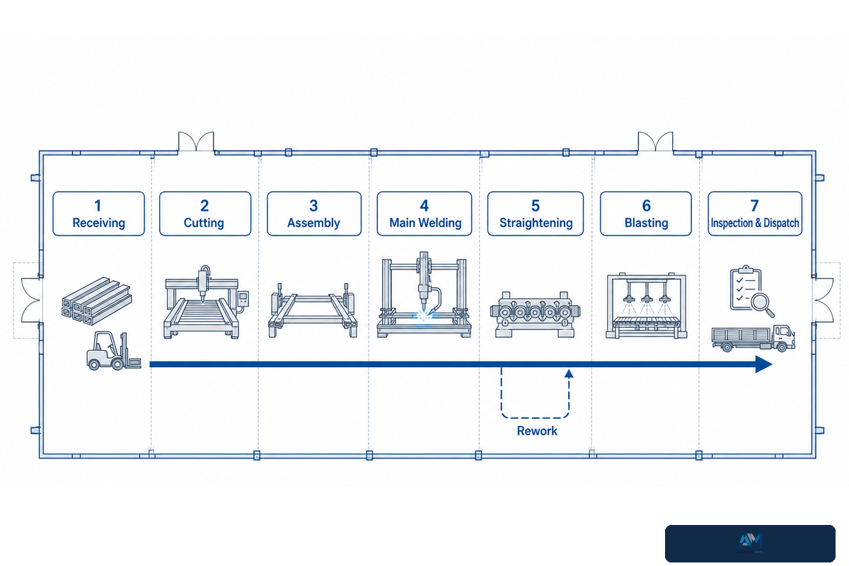
This 7-Zone Steel Flow Map transforms the manufacturing steps into planning areas in a steel facility. It’s an abstract conceptual framework, not a set of building codes or floor plans for a typical facility. Its function is to help identify crossings, lack of adequate buffer, and other production flow problems at a planning stage where changes can still be made.
| Zone | Primary job | Layout question | Required exception |
|---|---|---|---|
| 1. Receiving and stock | Unload, identify, and stage plate | Can inbound vehicles unload without entering finished-goods traffic? | Quarantine for unidentified or damaged material |
| 2. Cutting and preparation | Cut webs and flanges | Where do matched components wait without mixing? | Scrap and re-cut route |
| 3. Assembly | Fit and align the H section | Does the crane or roller system cover loading and unloading? | Fit-up correction hold |
| 4. Main welding | Complete longitudinal welds | Are gantry travel, power, flux, and extraction routes protected? | Weld repair and inspection access |
| 5. Straightening and correction | Correct distortion and verify dimensions | Can rejected work leave the main line without reversing every part? | Quality-hold and nondestructive testing point |
| 6. Blasting and finish preparation | Clean the surface and prepare for coating | Are entrance, chamber, dust plant, and exit treated as one envelope? | Bypass for work not ready to blast |
| 7. Final inspection and dispatch | Release, store, and load finished members | Can accepted work leave without crossing incoming plate? | Punch-list and document hold |
Quality planning works only when inspection criteria, qualifications, access, timing, reporting, and unresolved-item control are coordinated before fabrication.
A point of inspection need not be a new eighth zone of production. But it does need physical access, a hold, records and a release route, or it will become hidden work-in-process that clutters the main line.
4. Size Span, Crane Coverage, and Transfer Aisles as One System
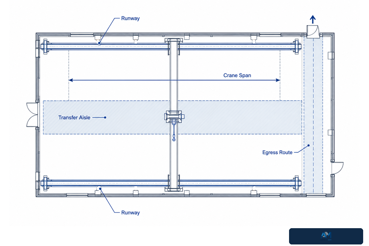
Clear span, crane reach, transfer aisles, and exit routes must be considered together because each one occupies or protects part of the same bay. Every handoff must pass the longest part; equally, employees must be able to access and exit from the process without having their route blocked by equipment or storage.
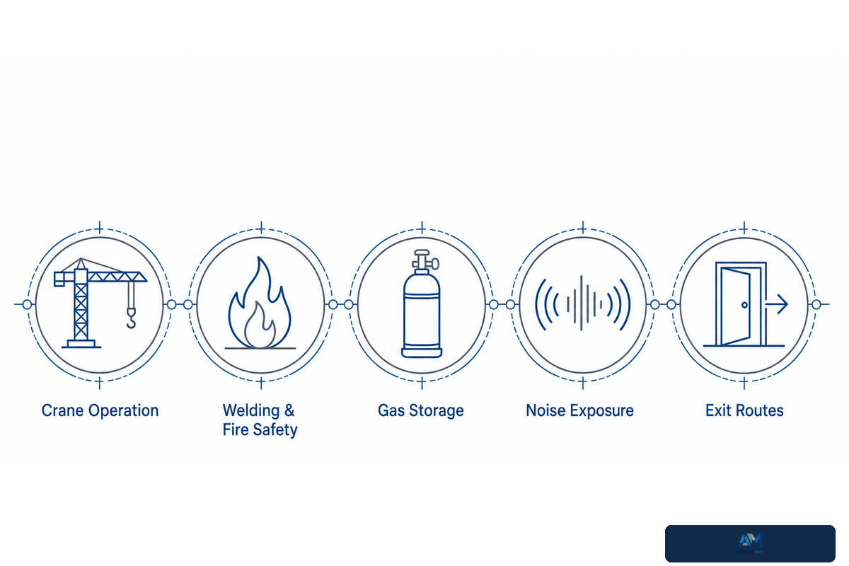
For United States projects, OSHA 1910.179 requires rated-load marking and addresses crane clearances, designated operation, and inspection. That provision includes minimum crane-to-obstruction clearances of 3 inches overhead and 2 inches laterally. Those numbers are regulatory boundaries for the crane; they don’t size the workshop, runway, building frame, or process route. Confirm the current text through the eCFR version of 29 CFR 1910.179.
OSHA 1910.37 also requires exit routes to remain clear, unobstructed, adequately lighted, and marked. They must be arranged to avoid paths toward high-hazard areas unless those paths are effectively protected. Consider egress requirements as a fixed input, not spare aisle space.
Crane and route check
- Plot every pickup, turn, set-down, inspection, rework, and maintenance lift.
- Mark hook approach and any blind or uncovered transfer point.
- Separate normal member movement from forklifts, pedestrians, exits, and emergency access.
- Confirm runway reactions, building support, lifting height, and maintenance access with qualified suppliers and engineers.
Planning scenario: A beam travels by rollers through assembly and welding, but the straightening machine sits beyond the crane runway. On a floor plan, the line appears continuous, yet a nonconforming member can’t be lifted to a side hold point. Extending the crane, relocating the hold point, or adding a defined transfer device are different solutions with different structural and cost effects. A sound answer comes from the exception route, not from a generic preference for more crane capacity.
5. Reserve the Real Equipment Envelope, Not Just the Footprint
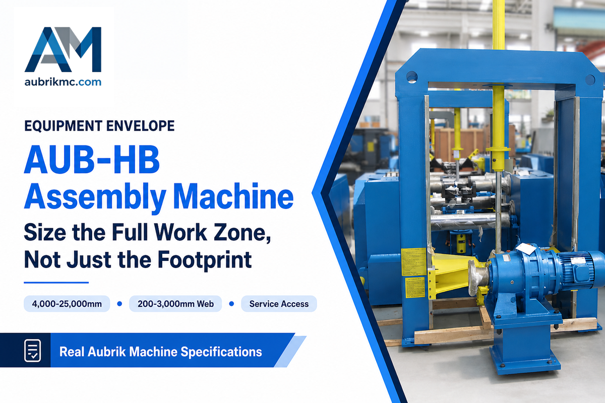
The footprint of a machine shows only the space it occupies while stationary. Its work envelope also includes inbound and outbound part length, rollers, guarding, the operator station, electrical control equipment, cable routing, fume or dust extraction connections, service access, and the path needed to remove significant internal components during maintenance.
Aubrik’s published AUB-HB assembly-machine range lists workpiece lengths of 4,000 mm–25,000 mm and web heights of 200 mm–3,000 mm. These are first-party configuration claims, not independent evidence of throughput or fit for a particular building. They show why the buyer’s maximum part length must appear on the layout before loading and unloading space is allocated.
The published AM-HG gantry welding range lists 4,000 mm, 5,000 mm, and 6,000 mm gantry spans and welding speeds of 300 mm/min–900 mm/min. A layout still needs the rail length, end clearance, flux equipment, welding power, extraction, operator access, and maintenance path. Welding speed alone can’t predict line output because fit-up, turning, inspection, buffers, and changeovers also consume time.
Aubrik’s steel shot blasting machine page publishes five model envelopes, with maximum listed workpiece sizes from 800 mm × 1,500 mm to 3,000 mm × 3,000 mm and maximum loads from 1,000 kg to 10,000 kg. Reserve entrance and exit length, dust collection, abrasive recovery, access doors, and maintenance space around the chamber. Don’t treat the chamber dimensions as the complete zone.
Illustrative length check
If the planning basis includes a 25 m member, one full-length inbound staging position plus one full-length outbound position already represents 25 m + 25 m = 50 m of linear allocation. That 50 m excludes the machine, rollers, guarding, transfers, exits, service access, and structural clearances. The calculation doesn’t prescribe a building length; it exposes an input that a footprint-only layout would miss.
6. Lock Utilities and Safety Controls Before Foundations
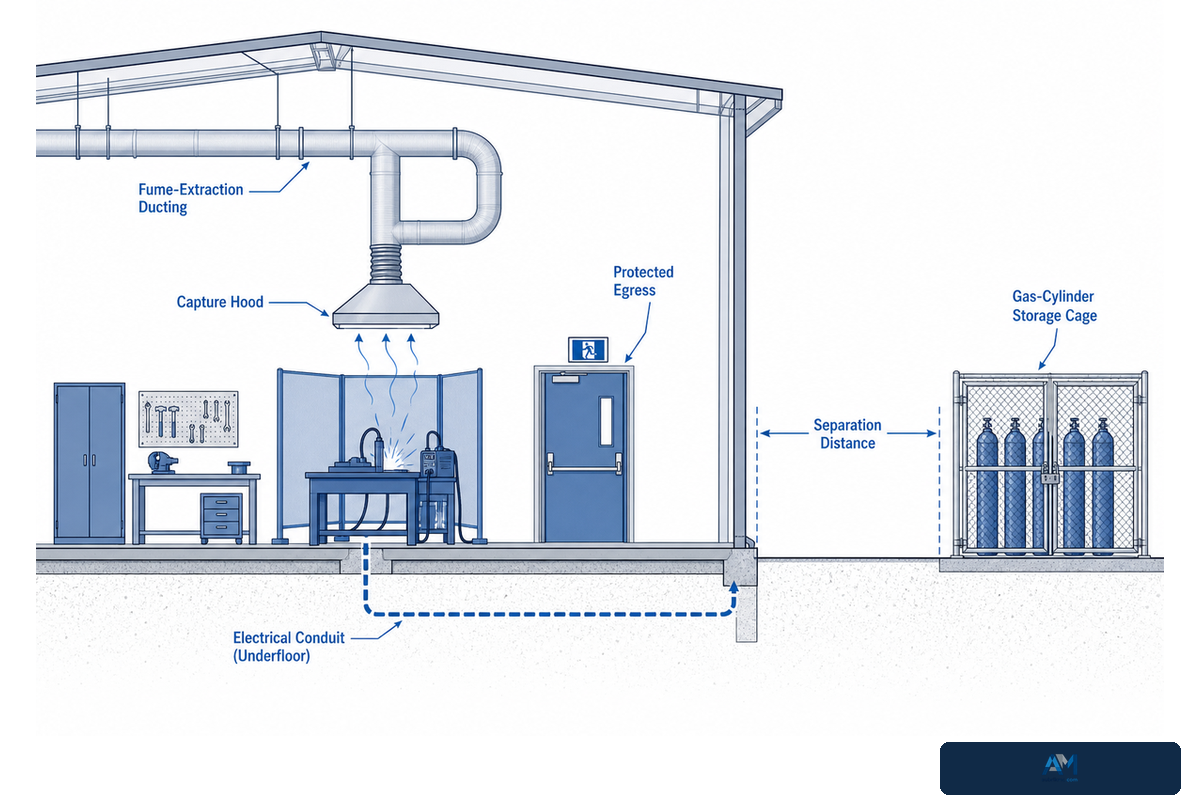
Utilities and safety controls belong in the early layout because ducts, gas storage, power distribution, dust collection, protected exits, noise controls, and maintenance isolation all need physical space. Moving a machine later may be easier than moving a foundation, crane column, buried service, or roof penetration.
For United States general industry, OSHA 1910.252 covers welding fire prevention, shielding, designated hot-work areas, and ventilation conditions. The AWS ventilation fact sheet explains that ventilation can be natural, mechanical, or both, and that local exhaust uses capture devices, ducting, and fans to remove fume at the source. Source capture affects torch access, hood position, duct routing, make-up air, and discharge location.
Gas storage is a separate spatial constraint. OSHA 1910.253 includes United States requirements for dry, ventilated and protected cylinder storage, quantity controls, and separation of oxygen from fuel gas or combustible materials. One cited option is 20 ft of separation; another uses a qualifying noncombustible barrier. Don’t copy that example into a global layout without checking the full current rule and the project jurisdiction.
Noise should also be measured rather than guessed from the machine list. OSHA’s noise guidance identifies an 85 dBA time-weighted-average action level over 8 hours in the United States and prioritizes engineering and administrative controls before reliance on hearing protection. Use the measured noise map to examine blasting, cutting, straightening, extraction fans, barriers, operator stations, and adjacent quiet work.
| Interface | Layout input | Verification owner |
|---|---|---|
| Electrical | Voltage, frequency, connected load, demand, cable routes, grounding, isolation | Electrical engineer and equipment supplier |
| Welding fume | Process, consumables, capture position, duct route, make-up air, discharge | Industrial hygienist or ventilation professional |
| Compressed and fuel gases | Consumption, storage quantity, ventilation, protection, separation, manifold route | Safety professional and local authority |
| Blasting dust | Collector location, ducting, abrasive recovery, access, waste handling | Dust-system and environmental specialists |
| Egress and fire | Exits, route protection, combustible control, extinguishing systems, hot-work zones | Fire/life-safety professional and local authority |
| Noise | Measured levels, exposure duration, barriers, enclosure, operator position | Industrial hygienist or qualified safety professional |
7. Find Backtracking and Bottlenecks on Paper
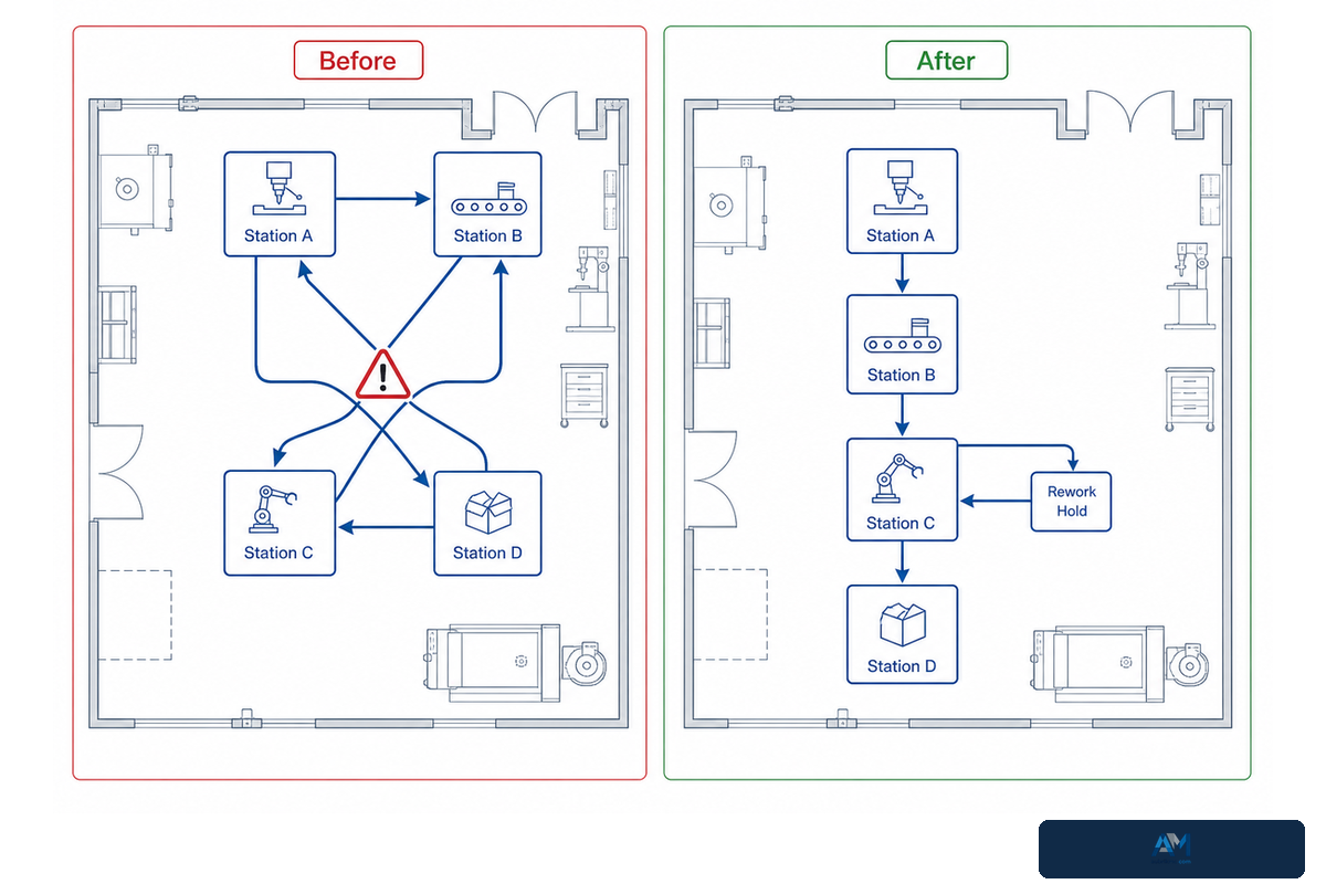
The easiest layout problem to solve is the problem you solve before construction. Trace a normal piece, a maximum length piece, a rejected piece, a maintenance removal, and an emergency exit route from start to finish. Each traced line proves one of the layout’s promises.
- Raw and finished routes cross. Separate their timing or physical path before forklifts and cranes compete for the same space.
- Crane coverage stops at a handoff. Define the transfer device and safe temporary support rather than assuming operators will improvise.
- The machine fits but the part doesn’t. Recheck loading, unloading, turning, guarding, and maintenance extraction.
- No buffer protects a slow station. Decide how many real members can wait and where their status is visible.
- Inspection creates reverse flow. Place the quality hold so accepted and rejected work have separate next steps.
- Expansion consumes the logistics spine. Preserve the end bay, runway continuity, utility corridor, doors, and external circulation needed for growth.
A credible layout doesn’t promise zero movement. It removes movement that doesn’t change, inspect, protect, or deliver the work. The Fabricator‘s shop-flow discussion connects efficient layout with controlled work-in-process and predictable capacity. That’s more useful than drawing the maximum number of machines inside the walls.
Illustrative bottleneck check: Suppose one repeat member averages 8 min in assembly, 14 min in main welding, 6 min in transfers, and 5 min in dimensional inspection. Welding is the theoretical constraint before downtime, quality holds, or a 20 min batch changeover is added. Two shifts of 8 hours don’t remove that constraint; they only extend the time in which it operates. These figures are placeholders for the method, not Aubrik performance claims. Replace them with observed cycle-time data for your actual product mix.
When not to buy a fully integrated line
Don’t default to conveyor integration when product routes change frequently, station cycle times are poorly understood, rework regularly leaves the main path, or the building can’t protect loading, maintenance, and exit clearances. Integration can reduce repeated lifts, but it also couples stations. If one process stops and the buffer can’t absorb the delay, upstream work may stop with it. A phased arrangement may be the better first step when demand is uncertain or the workshop must stay operational during expansion.
8. Apply the Span × Crane × Throughput Configuration Matrix
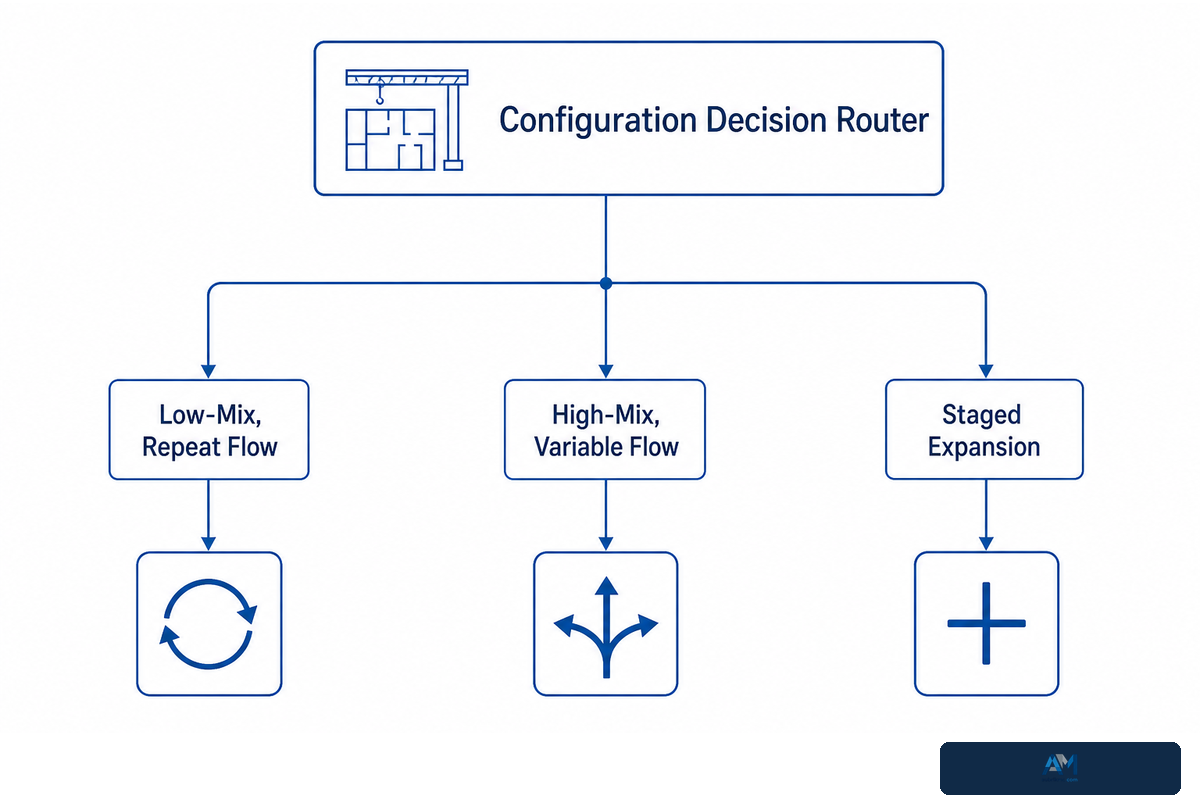
The Span × Crane × Throughput Configuration Matrix turns buyer inputs into a layout discussion. It isn’t a structural calculation or a machine recommendation. Use it to expose which decision changes when part mix, output, crane coverage, buffer capacity, or expansion timing changes. Treat the 29 CFR 1910.179 crane provisions as regulatory boundaries, not as a sizing formula for the matrix.
| Decision type | Low-mix, repeat flow | High-mix, variable flow | Staged expansion | Limitations / Not suitable for |
|---|---|---|---|---|
| Dominant route | Straight, repeatable sequence | Main route plus side cells | Protected future extension | No option handles undefined process steps |
| Member range | Narrow, stable range | Wide lengths and sections | Current range plus future maximum | Averages do not protect the maximum part |
| Handling | Rollers or conveyors for repeated transfers | Cranes and flexible transfer points | Interfaces ready for later conveyors | Conveyors do not solve off-line rework |
| Crane coverage | Exceptions, loading, turning, maintenance | Broad coverage for route variation | Runway continuity reserved | More coverage is not a substitute for flow |
| Buffers | Small, controlled work-in-process | Separate holds by route and status | Temporary capacity without blocking expansion | Floor area alone does not define buffer capacity |
| Inspection | Defined in-line hold points | Accessible off-line inspection | Records and access scale with phases | The matrix does not set code acceptance criteria |
| Utilities | Fixed services along the line | Flexible drops and isolated cells | Spare capacity and protected corridors | Spare capacity must be engineered, not guessed |
| Egress | Protected beside the repeat route | Protected through changing cell traffic | Maintained during each construction phase | Production aisles cannot automatically serve as exits |
| Expansion | Duplicate a proven module | Add flexible cells around the spine | Extend the line, crane, and utilities | Reserved space without interfaces is not expansion-ready |
Use the matrix in a workshop review with measurable inputs. If the team can’t state the heaviest lift, maximum member, required output, slowest likely station, and acceptable work-in-process, the layout isn’t ready for final optimization.
Steel Workshop Building Construction: A Customization Brief for the Workshop Supplier
Steel structure workshop construction decisions cannot be separated from steel structure workshop design. In a metal workshop, the steel workshop building may use prefabricated steel for its main frame, but a prefab steel package still has to carry the actual crane reactions, equipment loads, ducts, doors, and process openings. Treat workshop construction as an engineering handoff: the production team defines the work, while the steel structure design team checks the structural steel system, steel columns, foundations, bracing, roof, and wall panels. This boundary matters whether the project is a new custom workshop or the conversion of an existing industrial plant.
Do not accept broad claims about high strength, low cost, fast construction, or a broad application range as proof that one building concept fits the job. Large-span building structures can remove internal columns, yet their structural integrity must be checked for large loads, crane dynamics, strong winds, heavy snow, and the project’s seismic conditions. Compared with traditional buildings, a prefabricated system may change construction speed and on-site labour, but cost-effectiveness depends on local fabrication, transport, foundations, fire protection, enclosure, and erection constraints.
Before work reaches the construction site, ask who will prefabricate each package and which dimensions remain adjustable. Record permitted customization, fixed interfaces, and every customizable opening or support. An illustrative handoff might list a 24,000 mm span, a 20 t crane, a 300 kN runway reaction, and an 80 µm coating; these sample values show the required data format, not a recommendation. The programme should separate factory fabrication from on-site erection and show construction time, the overall construction period, and the construction timelines for crane rails, utilities, machines, extraction, and commissioning. It should also show how the contractor will control construction waste and keep protected routes open if industrial production continues nearby.
Durability inputs belong in the same handoff. Specify the operating environment, corrosion exposure, corrosion resistance system, drainage, flashing, and controls for water seepage; then connect inspection and maintenance access to the intended service life and practical lifespan. “Environmentally friendly” or “cost-effective” should remain qualified objectives until materials, energy use, maintenance, and replacement scope are compared for the actual site.
Custom Workshop Decisions for Modern Industrial and Traditional Buildings
Finally, tell the workshop supplier what the building will do. Requirements copied from logistics centers, commercial buildings, or another modern industrial project may miss the operational needs of welding, blasting, inspection, and heavy member handling. Large-scale industrial facilities and mixed commercial operations can share a shell vocabulary, but steel workshop design must still follow the specific product route. A useful proposal therefore links every structural and enclosure choice to a load case, operating constraint, construction sequence, or future change.
Why a Carport or Vertical Roof Template Is Not a Workshop Brief
Specifications copied from exhibition halls, a stadium, or a carport rarely address moving industrial loads, process extraction, inspection holds, and crane-supported maintenance. An enclosed production building may also need drainage, pest control, fire separation, and contamination controls that an open shelter does not. Reuse a proven detail only after the project team confirms that its load case, enclosure duty, access, and operating environment match the workshop.
9. Send a Production-Ready Workshop RFQ
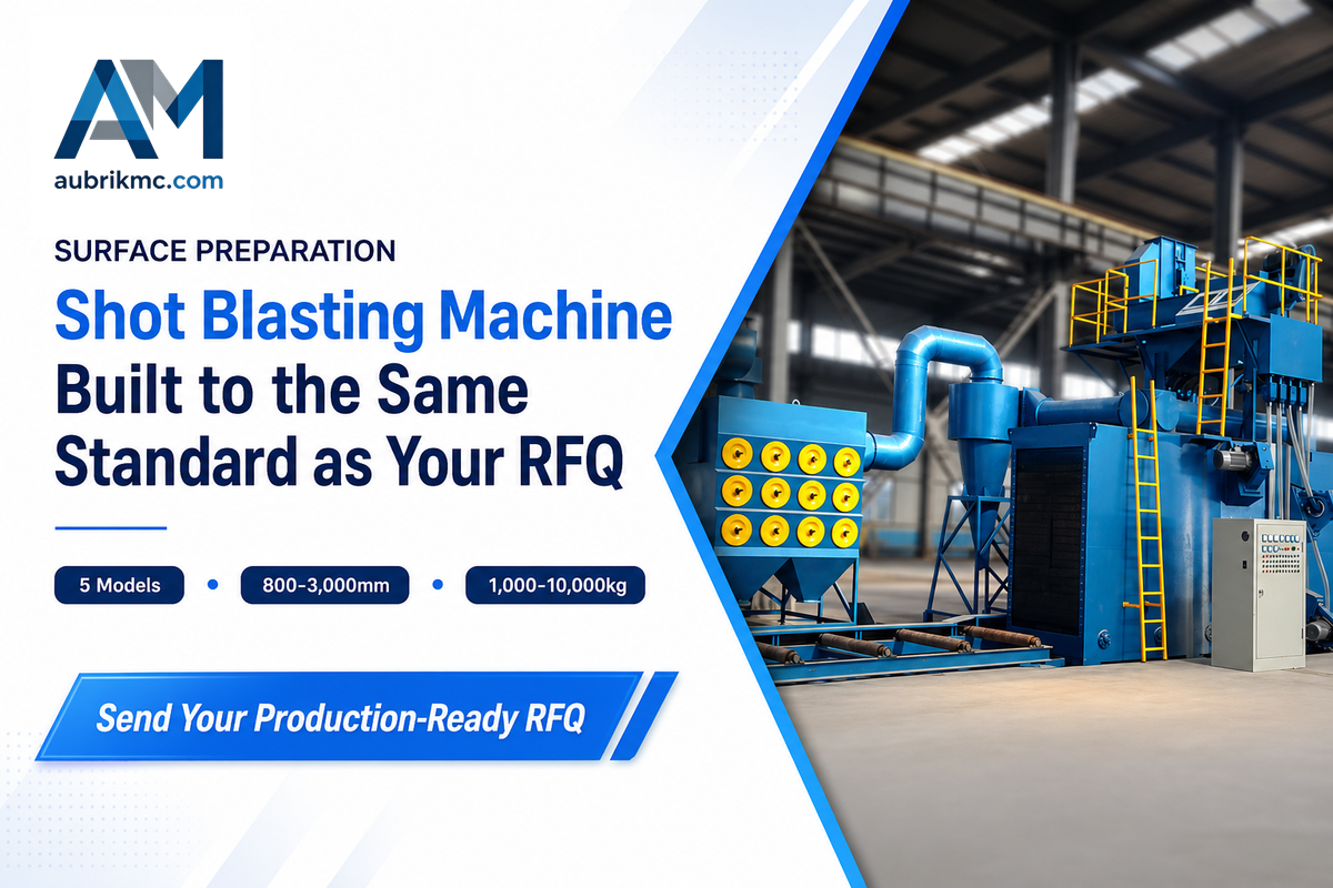
A useful request for quotation describes the production problem in measurable terms. Copy the table below into your inquiry, fill in the blanks, and attach a scaled building or site drawing where available.
RFQ checklist — copy these into your quote request:
| Parameter | Recommended range | Why it matters | How to verify |
|---|---|---|---|
| Member range | Min/max web, flange, thickness, length in mm | Controls equipment and handling envelope | Approved product drawings |
| Heaviest lift | Maximum kg or t at each handoff | Controls crane and support inputs | Weight calculation and lift review |
| Output and shifts | t/year or pcs/year; shifts/day | Sets cycle and buffer questions | Production forecast and part mix |
| Available building | Length × width × clear height in mm | Reveals route, door, and service constraints | Scaled survey or building drawing |
| Electrical and air | V/Hz/phase, available kW, air pressure and flow | Prevents utility mismatch | Utility schedule and site measurement |
| Extraction and dust | Processes, consumables, capture points, local limits | Controls duct, collector, and make-up air plan | Industrial-hygiene and environmental review |
| Safety and egress | Exit, fire, gas-storage, noise, guarding requirements | Protects people and approval path | Local code and risk assessment |
| Quality and acceptance | Hold points, NDT, records, trial material, acceptance tests | Defines access and release evidence | Project quality plan and witnessed test |
Use Aubrik’s H-beam line configuration selector to structure the equipment discussion when the process family isn’t yet fixed. A supplier can challenge the brief more effectively than a request that gives only a floor area.
10. Choose Standalone Machines or an Integrated Line
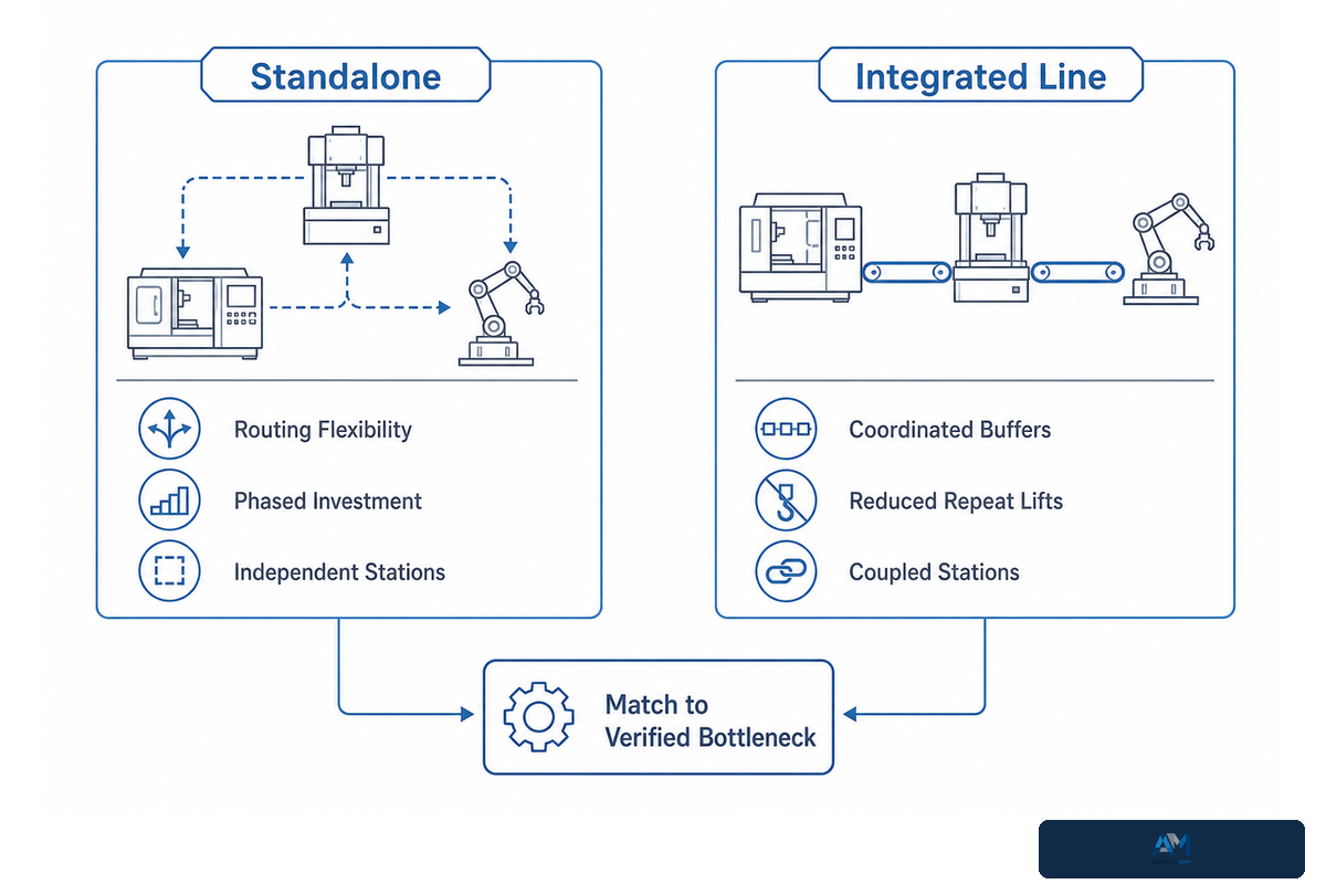
Standalone equipment and integrated conveyors solve different constraints. Standalone machines preserve routing flexibility and phased investment. Integrated handling becomes more valuable when repeated lifting, staging, and transfer, not the process itself, is the demonstrated bottleneck; The Fabricator‘s structural-shop material-handling review provides relevant industry context.
Compare station cycle times, changeovers, part mix, quality holds, maintenance events, and exception frequency. An integrated line needs buffers and bypass logic because a stopped station can affect upstream and downstream work. A standalone arrangement needs disciplined staging because flexible routing can turn into uncontrolled work-in-process.
Planning scenario: A repeat product family runs through assembly, gantry welding, straightening, and blasting most days, while special members require extra fitting and inspection. The repeat family may justify coordinated rollers and controls, but the special route still needs crane access and a side hold. The decision isn’t integrated versus standalone for the whole plant. It can be an integrated spine with deliberately flexible exception cells.
Key takeaway
Choose the workshop, crane, and handling system from the verified part route and its exceptions; do not make production adapt to a shell selected from floor area alone.
Frequently Asked Questions
What is a steel workshop?
Answer
A steel workshop is an industrial building whose primary structural frame is made from steel. For fabrication, the useful definition is broader than the shell: the workshop also contains a planned route for stock, parts, cranes, welding, correction, inspection, surface preparation, storage, and dispatch. The best arrangement depends on the product and process rather than floor area alone.
What are the key design considerations for a steel workshop?
Answer
Key inputs include product range, target output, process sequence, span and column grid, crane reach, floor and foundation loads, machine operating envelopes, doors and logistics, protected exits, power, fume and dust extraction, gas storage, fire control, noise, inspection access, buffers, maintenance, and expansion. Structural design and regulatory compliance must be checked by qualified professionals for the project location.
Can steel workshops be customized to specific needs?
Answer
Yes. Bay dimensions, crane systems, doors, equipment sequence, utilities, extraction, buffers, inspection points, and expansion interfaces can be configured around the required products. “Custom” should be translated into measurable inputs such as maximum member size, heaviest lift, annual output, shift pattern, local design loads, acceptance tests, and available site services.
How much does it cost to build a steel structure building?
Answer
No universal cost per square metre is reliable. Price the project-specific structure, cranes, foundations, enclosure, fire protection, utilities, equipment, installation, certification, site work, and explicit exclusions.
Can I expand my steel workshop later?
Answer
Expansion is practical only when the original plan preserves the required interfaces. Reserve an expansion end or side, external circulation, future doors, crane-runway continuity, structural load paths, utility capacity, extraction routes, control and data connections, conveyor alignment, and safe access during construction. Protect current exits and production while the new phase is built. Sequence the new work so crane and logistics interfaces can be commissioned without trapping current production. Empty land beside a workshop doesn’t by itself make the plant expansion-ready.
Is a steel building cheaper than concrete?
Answer
Either system may be more economical in a specific project. Project economics depend on local material and labour prices, span, crane and roof loads, foundations, fire protection, schedule, durability requirements, operating environment, and future modification. Compare equivalent scopes and lifecycle requirements rather than shell prices alone.
For United States safety boundaries referenced in these answers, consult the linked OSHA crane and exit-route provisions; local requirements still control the project.
Plan the Workshop Around the Work
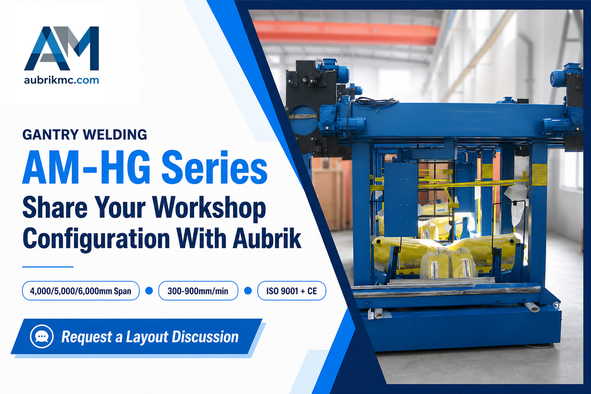
A solid steel structure workshop brief maps the complete flow for every normal and special part. It defines each crane’s range, access point, and material route, while clearly locating supporting utilities and protected paths to every exit.
Send Aubrik your standard member sizes, maximum lift, major material-flow stages, production-rate requirements, site constraints, utility provisions, inspection criteria, and overall facility guidelines. Instead of relying on a generic square-metre calculation, Aubrik can develop a system configuration that can be quoted, installed, and accepted against defined requirements.
Prepare your workshop configuration
Share your H-beam range, target output, available building dimensions, crane constraints, and required process stages with Aubrik.
Related Articles and Tools
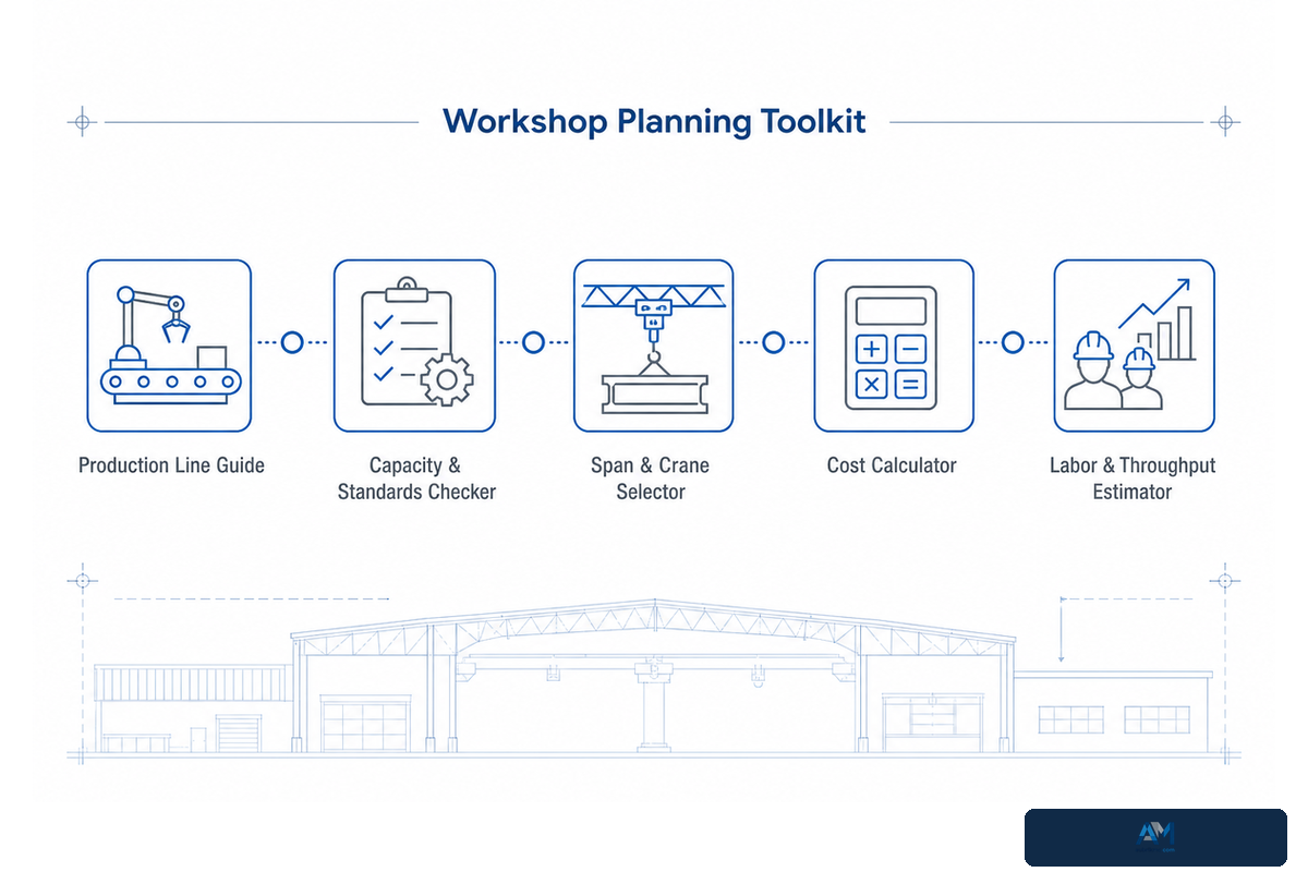
- H-beam steel structure production line guide
- H-beam capacity and standards checker
- Span, crane, and workflow selector
- Workshop cost calculator
- H-beam labour and throughput estimator
References & Sources
- OSHA 1910.179, Overhead and gantry cranes
- Electronic Code of Federal Regulations, 29 CFR 1910.179
- OSHA 1910.252, General welding, cutting, and brazing requirements
- OSHA 1910.253, Oxygen-fuel gas welding and cutting
- OSHA 1910.37, Exit-route maintenance, safeguards, and operational features
- OSHA Technical Manual, Noise
- American Welding Society Fact Sheet No. 36, Ventilation for Welding and Cutting
- American Welding Society, Standards and Publications
- American Welding Society, Inspection Trends, Quality Planning
- The Fabricator, Finding flow with an efficient shop-floor layout
- The Fabricator, Modern material handling in the structural fab shop
- Texas Department of Insurance, Metal fabrication shop safety
United States sources illustrate specific regulatory boundaries. The project’s local building, structural, electrical, fire, environmental, and occupational-safety requirements control the final design.