Get in Touch with Aubrik Company

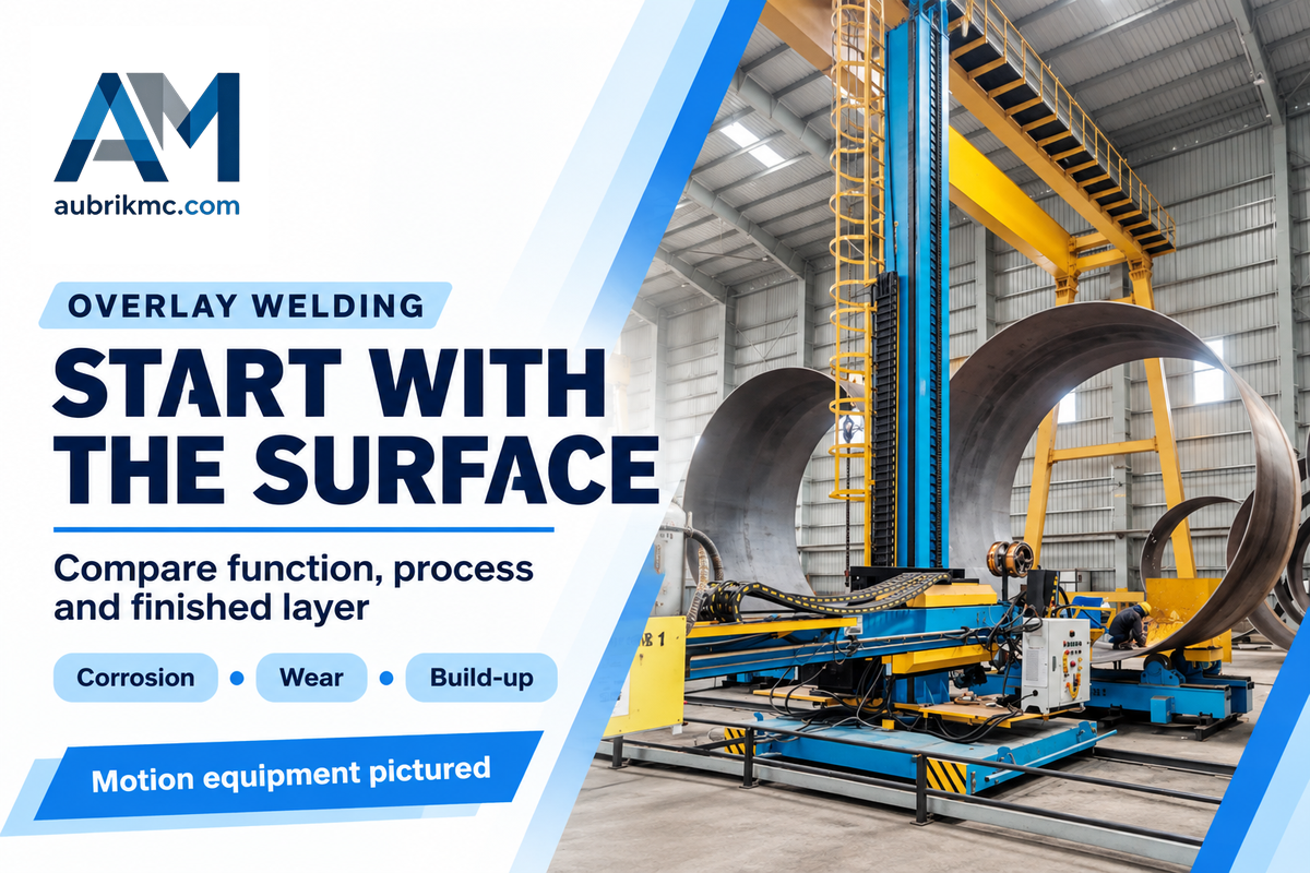
Overlay welding uses deposits for corrosion resistance, wear reduction or dimensional restoration. Starting with the job to be done by the working surface is essential to choosing an overlay. For instance, a valve in contact with corrosive fluid, a bucket tooth working in abrasive soil and a worn shaft all require different deposits, even though they’re all described as weld overlay.
Updated October 2026
Quick guide
- Corrosion: select the deposited alloy for the fluid and operating environment.
- Wear: match the hardfacing material to abrasion, impact or sliding contact.
- Size restoration: select compatible build-up metal and leave the required finishing stock.
- Equipment: match torch access, workpiece motion and the welding process.
Overlay welding adds a fused surface layer to an existing part. Corrosion cladding changes the exposed chemistry; hardfacing resists wear; build-up restores dimensions. Select the surface function before choosing the process or machine.
Key points
- Low dilution can coexist with poor fusion between adjacent beads.
- Equal hardness doesn’t mean equal wear resistance across different alloy families.
- Finished thickness and deposited thickness are different when machining removes material.
- A motion platform and a complete welding process package cover different purchasing needs.
What is overlay welding used for?
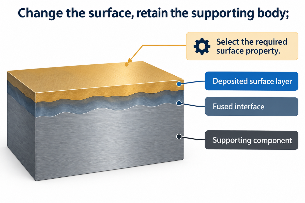
Overlay welding is a process used to change the working surface of a part while retaining its supporting body. A corrosion-resistant alloy can protect a valve passage. A hardfacing deposit can provide abrasive wear resistance. Compatible metal can build up a diameter before it’s machined. The surface property required of the part determines the next material and process choice.
What is a weld overlay?
A weld overlay is metal deposited and fused onto another metal surface. In this fusion welding process, filler and a portion of the substrate melt at the interface. The bond is of a different kind from loose liner attachment or unfused spray-on coatings. Deposited metal maintains the desired surface properties while the underlying component supports it.
Welding has long been used to join separate pieces, but surfacing covers an area of an existing piece. These may use the same types of power sources and consumables but their purposes differ: deep penetration in a joint can mix too much of the substrate into an overlay. TWI describes this material and process relationship in its weld-cladding overview.
Applications of overlay welding include valve surfaces, pump components and worn industrial parts. Across these industries and applications, a damaged metal surface is only the starting observation. Corrosion removes material chemically, while abrasion removes it mechanically. Restoring the missing metal without addressing the damage mechanism can leave the replacement surface exposed to the same problem.
Cladding, hardfacing and build-up: choose the function
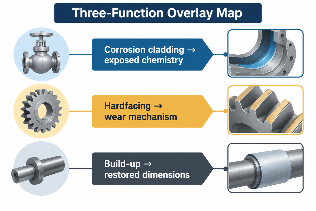
Choose corrosion cladding when the exposed surface needs different chemistry, choose hardfacing when wear controls replacement, and choose build-up when the dimensions of the part need to be restored. These functions can be combined on the same component. A rebuild layer can support a harder final layer, but the two layers aren’t interchangeable.
Three-Function Overlay Map
The Three-Function Overlay Map determines the function of a job by its surface duty, and identifies what the final surface layer should demonstrate.
| Function category | Workpiece situation | Material decision | Finished-part question |
|---|---|---|---|
| Corrosion cladding | Valve passage | Select deposited chemistry for the fluid | Retain the required composition after finishing |
| Corrosion cladding | Pump wetted surface | Consider the fluid and operating environment | Define coverage and finished surface condition |
| Corrosion cladding | Part exposed to both corrosion and abrasion | Evaluate combined damage rather than hardness alone | Decide which service mechanism controls material choice |
| Hardfacing | Bucket tooth in abrasive soil | Balance abrasion resistance with impact tolerance | Keep the deposit supported by sound material |
| Hardfacing | Sliding metal-contact surface | Select material for the contact mechanism | State the loading and contact conditions |
| Hardfacing | Abrasive surface with cooling check cracks | Separate permissible checking from unacceptable damage | Use acceptance criteria for the intended wear duty |
| Build-up | Worn shaft diameter | Choose compatible and machinable deposit | Allow enough stock to reach final dimensions |
| Build-up | Worn tooth beneath a hardfacing layer | Match rebuild metal to substrate and final overlay | Restore support before applying the wear layer |
| Build-up | Repair into an existing butter layer | Identify the retained layer and removal depth | Define the remaining material before procedure selection |
What is the difference between overlay and cladding?
The difference between cladding and weld overlay refers to the scope of the terms. The weld overlay process refers to a fusion-based process, and cladding refers to adding a different surface material more broadly. Cladding and weld overlay are often used interchangeably in welding quotations, but other cladding processes join layers by different means. Therefore, a purchasing description should identify the bonding method as well as the surface alloy.
Using the phrase cladding and overlay processes can also obscure the distinction in what the surface is for. Hardfacing controls wear, while corrosion-resistant weld overlay cladding addresses the service environment. Build-up can precede either. In its hardfacing guidance, the American Welding Society describes the selection of rebuild material as being dependent on compatibility with the base metal and the final overlay.
Compare overlay welding processes by the workpiece
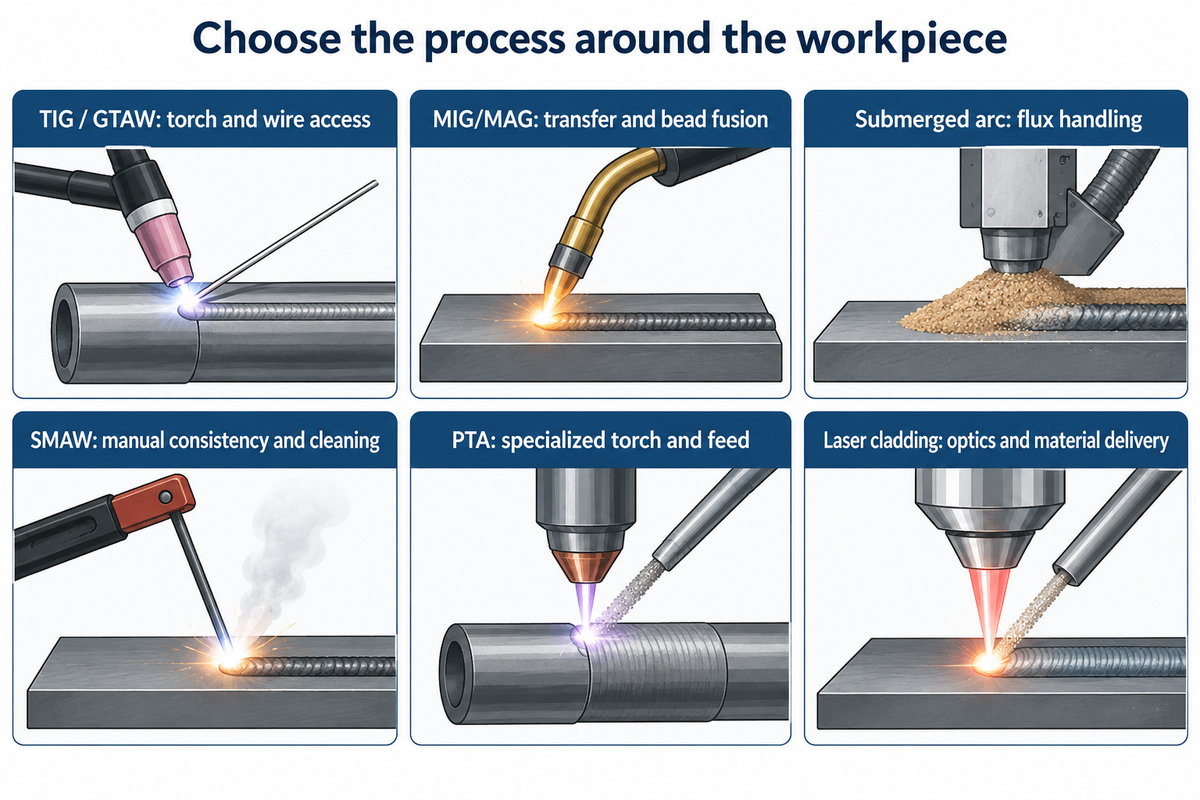
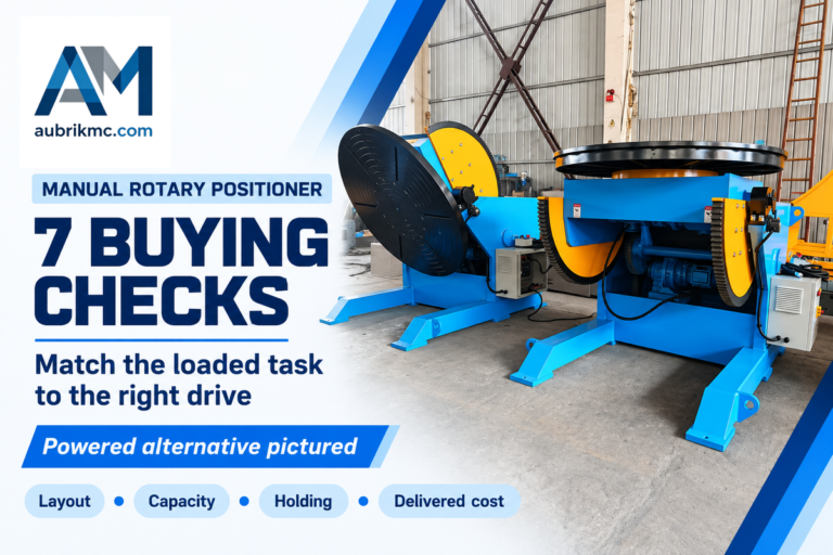
Access and surface shape drive the short-listing process. TIG is a candidate for controlled deposition around accessible bores and detailed surfaces; wire-fed arc processes are viable for repeatable coverage; for submerged arc, space needs to be provided for the head and flux. Local repair can favor portable equipment, while specialized plasma or laser systems need their own integration. For manually adjusted orientation, a manual rotary positioner is an alternative workholding choice.
| Welding method | Workpiece fit to examine | Hidden bottleneck | Buyer decision |
|---|---|---|---|
| TIG / gas tungsten arc welding | Bores, sealing surfaces and controlled local deposits | Torch and wire access throughout the path | Compare the actual head envelope with the smallest opening |
| MIG/MAG / gas metal arc welding | Repeatable wire-fed surface coverage | Stable transfer, shielding and bead-to-bead fusion | Compare deposited geometry as well as nominal output |
| Submerged arc welding | Broad surfaces with room for head and flux handling | Flux containment, recovery and work orientation | Include flux handling in the layout and cycle |
| Shielded metal arc welding (SMAW) | Accessible local repair and intermittent work | Manual consistency and cleaning between passes | Compare the complete repair cycle before buying automation |
| Plasma transferred arc / PTA welding | Dedicated hardfacing and surfacing applications | Specialized torch, consumable feed and access | Specify the complete process package |
| Laser cladding | Localized deposition with a suitable beam and feed path | Optics, material delivery and process integration | Evaluate the surface requirement with the laser-system supplier |
Gas tungsten arc welding utilizes a non-consumable tungsten electrode. Tungsten inert gas (TIG welding) uses filler supplied separately from the electric arc. MIG welding feeds the consumable wire electrode into the weld pool. The shielding gas may be inert (metal inert gas) or active (metal active gas, MAG). The distinctions between these processes affect the power source, wire feed and gas arrangement.
For a more in-depth discussion on cold- and hot-wire TIG, dilution, acceptance and batch costs, refer to the TIG overlay welding guide. This broader comparison outlines which families should be shortlisted. Arc welding processes should not be ranked by one advertised deposition rate without considering the part. The usable welding positions also factor into the families shortlisted.
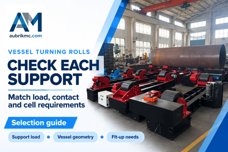
Let’s look at a shop considering two opportunities: a valve bore and the outside of a cylindrical shell. The bore controls the size of the torch and the approach of the wire before welding starts. The shell offers more space, but its rotation must hold the deposit in a workable position while the head traverses. A welding technique that fits the shell may not be able to be positioned inside the valve. For the shell, a column and boom welding manipulator carries the head, while welding rotators and turning rolls take care of the motion of the workpiece. For the valve, a compact head and proper fixture come first. The production manager isn’t helped by an increased process speed if loading, access or repositioning consume the time saved during deposition.
Select the overlay alloy for the damage mechanism
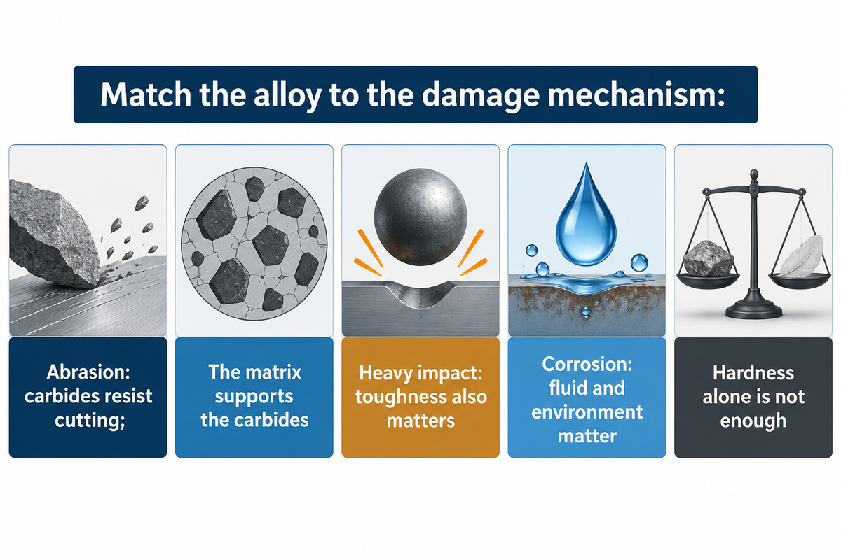
Select the overlay alloy for the damage that limits the part’s service life. Abrasion tends to favor a combination of different carbides and matrix properties compared to heavy impact or sliding metal contact. Corrosion resistance depends on the properties of the fluid and the operating environment. The highest hardness reading by itself doesn’t address these requirements.
In a hardfacing primer published by The Fabricator, materials engineer Bob Miller discusses why a martensitic deposit and a chromium-carbide deposit can perform differently, despite having similar hardness. Carbides resist abrasive cutting while the matrix supports them, and heavy impact can make toughness as important as resistance to scratching.
“The hardness of a hardfacing deposit is not the deciding wear-resistance factor.”
Filler materials based on nickel and cobalt can cover applications with corrosion and wear. TWI provides Alloy 625 in pump and valve applications as an example and cobalt alloys for combined corrosion and abrasion as another example, and these are material families to consider, rather than substitutes chosen purely by trade name. Oil and gas equipment also introduces operational conditions that differ from ordinary dry wear.
One example of a tradeoff is illustrated by a bucket tooth that encounters abrasive soil and occasional rock impacts. Using only the hardest deposit ignores the loads that can chip or detach it. A rebuild layer may first restore the tooth shape, and the hardfacing may carry the wear duty in service. The filler for the supporting layer must be compatible with the substrate and final deposit. On the other hand, the same hardfacing choice is unsuitable as a shortcut to a fluid-tight corrosion barrier. Some of the chromium-carbide hardfacing alloys develop checking cracks during cooling. A corrosion layer has a different function, so its acceptance can’t be borrowed from that particular wear application.
Why dilution and bead overlap change the result
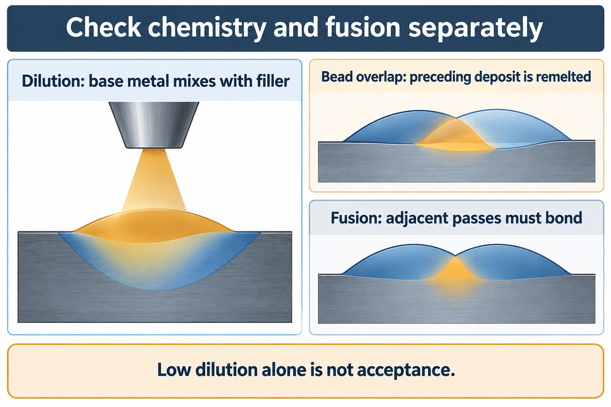
Chemistry of an overlay changes with dilution. Base metal melts and mixes with deposited filler during dilution. Bead overlap changes how much of the preceding deposit is remelted and whether adjacent passes fuse. Both factors affect the final finished layer. Reducing dilution can trade one problem for the other if fusion isn’t maintained.
Dilution effects in TWI’s 2010 Alloy 625 overlay experiments showed that varying the combination of welding current and speed resulted in varying dilution at approximately the same heat input. The work also revealed that a tall weld bead of a low-dilution controlled short-circuit transfer can create a shape that increases the likelihood of a lack of fusion at the weld toe during the deposition of the subsequent bead.
That finding accounts for why the welding parameters are combined. An energy input figure can’t explain every transformation in the weld pool. The first bead also melts immediately into the substrate, and subsequent passes overlap deposited weld metal. Chemistry measured at one position may therefore differ from chemistry elsewhere in the layer.
Arc welded overlays require adequate fusion and the required final composition. Excessive mixing can reduce the intended alloy content; inadequate fusion leaves an interface defect. The performance of the weld is affected by both. A section through a representative deposit reveals different facts from a picture of the deposit’s surface.
Can you weld on top of another weld?
Yes, overlay procedures can deposit additional metal on a sound existing weld or supporting layer. The existing material must be identified and suitable for the procedure. Repairing over cracked or degraded metal is a completely different job from adding the next planned pass. Retained defects and unknown previous deposits can affect the new metal layer.
In a Stellite repair discussion on Eng-Tips, various outcomes for repair removal are attributed to the underlying alloy and whether the removal reaches a butter layer or the substrate. The helpful buying question is the depth and condition of the repair, not a temperature quoted from a different shop.
What drives overlay welding cost?
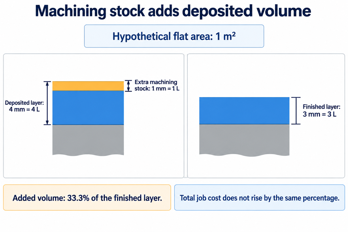
Deposited volume, filler cost, preparation, welding time and finishing drive job cost. Equipment ownership adds installation, training and maintenance costs. Thicker deposits require more material and may require more machining. For this reason, the cost of the finished job shouldn’t be based on the cost of the quickest arc-on operation.
Calculate the material removed by finishing
Example: A 1 m² flat area requires a finished overlay of 3 mm. The geometric retained volume is 1 m² × 0.003 m = 0.003 m³ = 3 L. If 1 mm of stock is lost during machining, the original deposit is 4 mm (4 L). The extra 1 L of deposited volume provides a 33.3% increase over the finished layer volume (3 L).
The sensitivity table keeps the area at 1 m² and varies the assumed finished thickness and machining stock. These are calculation inputs, not recommended weld-layer thicknesses or machining allowances. Actual values come from the component requirements and qualified procedure.
| Finished thickness | Assumed extra stock | Deposited thickness | Deposited volume at 1 m² | Volume increase over finished layer |
|---|---|---|---|---|
| 3 mm | 0.5 mm | 3.5 mm | 3.5 L | 16.7% |
| 3 mm | 1 mm | 4 mm | 4 L | 33.3% |
| 3 mm | 1.5 mm | 4.5 mm | 4.5 L | 50% |
| 3 mm | 2 mm | 5 mm | 5 L | 66.7% |
| 5 mm | 0.5 mm | 5.5 mm | 5.5 L | 10% |
| 5 mm | 1 mm | 6 mm | 6 L | 20% |
| 5 mm | 1.5 mm | 6.5 mm | 6.5 L | 30% |
| 5 mm | 2 mm | 7 mm | 7 L | 40% |
The calculation focuses on machining stock. It does not make total cost rise by the same percentage: labor, setup, deposition losses and inspections have different cost drivers. Finance can compare the extra material volume to assess material usage, while production can assess the time required to deposit and remove the volume. On a curved part, the volume calculation must follow the component geometry instead of this flat-area approximation.
NIST’s equipment purchase guidance separates ancillary equipment, utilities, training and maintenance in the buying decision. The same concept can be used to compare welding machines. A price for a motion unit can’t be directly compared to a price for a complete process head, controls and commissioning.
Outsource the overlay job
- Purchase a finished component or defined repair service.
- Include transport and supplier lead time.
- Compare repeat-order availability and finishing scope.
Bring deposition in-house
- Purchase equipment and establish the process capability.
- Include installation, training and maintenance.
- Compare expected workload and the required supporting operations.
Match automation to the part and supply package
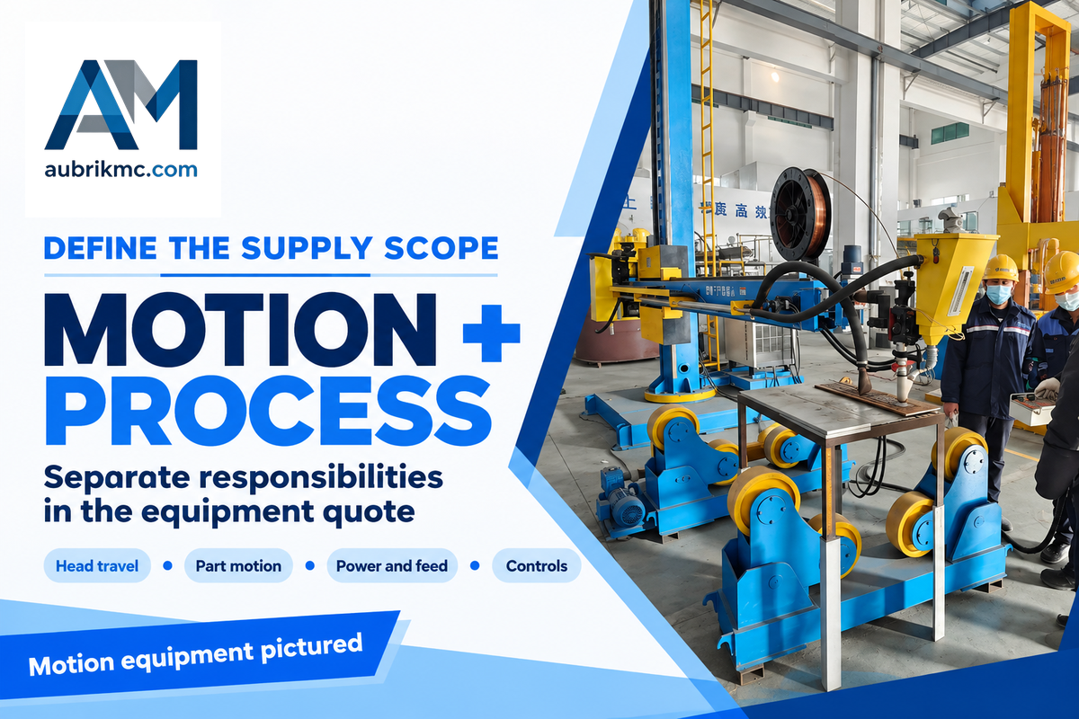
Match an automated welding system to the workpiece path, loading method and process equipment. A column-and-boom manipulator moves the welding head; a positioner or rotator moves the part. A complete process package also needs the right power source, consumable feed and controls. Those responsibilities should be separated in the quote.
Aubrik supplies column-and-boom welding manipulators for movement of the welding head including TIG and cladding applications. A flange or other compact part may instead need controlled orientation on a welding positioner. Reach and clearances are defined by a workpiece drawing. The choice of overlay technique defines the arrangement of the head and feed.
For an in-house cell, the welding equipment supplier and process specialist may cover different work. The equipment quote describes the hardware supplied and the integration. The welding procedure describes how the deposit is made. ISO 15609-1:2019 specifies the contents of arc-welding procedure specifications, a separate task from selecting a machine frame.
For intermittent repairs, weld overlay services may be more appropriate than having a dedicated cell. A shop with repeat parts can compare an in-house cycle to the outsourcing lead time. Even with automated head travel, a welder still requires access for cleaning, consumable changes and for observation. Loading and finishing are still part of the process route.
Define the finished surface before a production trial
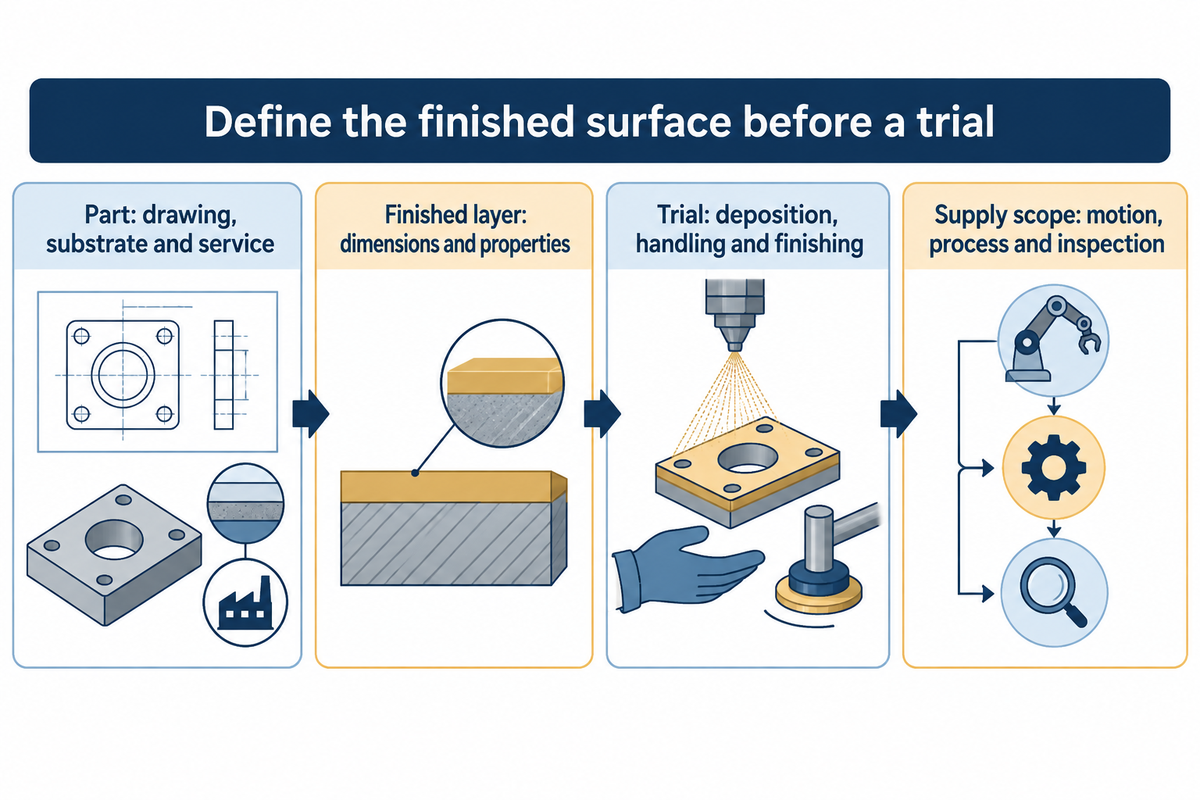
Provide finished dimensions, substrate, service environment and required surface properties before comparing welding trials. Record the conditions after final machining since machining can expose a different depth of deposit. The trial should represent the geometry of the production part, and include a method of examination to reveal relevant defects.
ISO 15614-7:2016 addresses qualification of overlay welding procedures by testing. Procedure tests made under previous editions of this standard are not invalidated by this edition. Parent metals are built up and repaired according to the routes stated in this standard’s scope. The applicable qualification range will govern the work being proposed.
Inspection capability is specific. A 2012 Pacific Northwest National Laboratory study of two overlaid dissimilar-metal specimens found that lower-frequency probes gave coherent signals yet could not reliably detect the smallest flaws in that study. A strong signal alone is therefore an incomplete basis for choosing the examination setup. TWI also describes interface disbonding in high-temperature hydrogen service; an attractive initial deposit doesn’t rule out that service risk.
- Describe the part. Supply a drawing, substrate identity, existing deposit condition and service environment.
- Define the finished layer. State the required final dimensions, surface properties and machining allowance.
- Compare the trial. Record deposition, handling, finishing and inspection as separate operations.
- Allocate the supply scope. Confirm who provides the motion equipment, process package, procedure qualification and inspection.
When seeking equipment, provide the smallest bore, largest envelope of the workpiece, and loading arrangement. If multiple types of weld or repair share a station, state which ones must be supported on the same fixture. This information allows the supplier to compare different techniques against actual parts, not a generic capacity description.
Frequently asked questions
Is overlay welding the same as an overlap defect?
No. Overlay is intentional surfacing; an overlap defect is unfused metal at an edge.
An overlay welding process deliberately deposits metal on a substrate. Overlapping adjacent beads is a normal way to cover the surface, provided those beads fuse properly. An overlap defect describes metal flowing beyond the weld toe without adequate fusion. The similar words describe different things: one is the intended operation, while the other is an unwanted discontinuity in the resulting deposit.
What Base Metals Can Have Weld Overlays?
Carbon steels, alloy steels and several other metal families can receive suitable overlays.
Hardfacing guidance includes stainless steel, manganese steel, cast iron and nickel-based materials among possible substrates. That list is a starting point for selection. The exact base metal controls compatibility and thermal treatment, while the service requirement controls the deposit. A material that accepts one overlay weld doesn’t automatically accept another filler or repair method. Existing surface damage also needs to be addressed before deposition.
What Are the Benefits of a Weld Overlay?
A weld overlay can improve surface performance or restore dimensions while retaining the supporting part.
The benefit comes from putting the selected material where the surface needs it. A corrosion-resistant layer can separate the working fluid from the underlying substrate. Hardfacing can reduce wear, while build-up can restore metal needed for final machining. Savings depend on the complete repair or manufacturing route, including preparation, deposition and finishing. The appropriate benefit is therefore tied to the component’s damage mechanism and service requirement.
Is there one correct overlay thickness?
No. The required finished thickness and machining stock set the deposition target.
Geometry, alloy composition through the layer and the qualified procedure affect the result. Use the finished dimension when comparing deposits, rather than treating the as-welded thickness as the final requirement.
Does a welding manipulator include the complete overlay process?
A manipulator provides head movement; complete process scope must be specified separately.
A package can include additional equipment, but the quoted scope determines what arrives. The power source, filler delivery, shielding arrangement, process controls and commissioning responsibilities belong in that scope.
Discuss the motion equipment for your overlay application
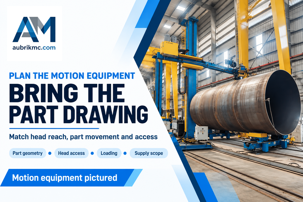
Send Aubrik the workpiece drawing, proposed welding process and loading arrangement to discuss head travel, reach and workpiece positioning.
Technical basis: This advice is based on published welding guidance and the cited research. The example uses hypothetical dimensions. No production trials were conducted for this article.
References & Sources
- A primer on hardfacing metal, Bob Miller, The Fabricator.
- 25 Hardfacing Tips, Guy Chouinard, American Welding Society, 2024.
- Manufacturers: Pre-Purchase Guide for Equipment, National Institute of Standards and Technology, 2020.
- ISO 15609-1:2019, International Organization for Standardization.
- ISO 15614-7:2016, International Organization for Standardization.
- Ultrasonic Evaluation of Two Dissimilar Metal Weld Overlay Specimens, Pacific Northwest National Laboratory, 2012.