Get in Touch with Aubrik Company

How Steel Wind Turbine Tower Sections Are Made and Released

A finished tower section requires more than a welded cylinder at each handoff. The fabricator needs an identifiable part, an approved acceptance source, and a record to show whether or not work can proceed. This reference covers the wind tower manufacturing process up to factory delivery and offers two blank worksheets that can be included with a request for quotation. This reference outlines steel sections for wind energy and wind power projects and doesn’t include the complete turbine.
Scope: The following is an example of a conventional rolled plate tubular steel tower. The actual checks depend on the drawings, contract, location, and fabrication route. Foundations, nacelles, turbine aerodynamic components and site erection also have their respective scopes. Aubrik provides production-line equipment; this article doesn’t claim Aubrik manufactures complete towers.
Wind tower manufacturing process at a glance
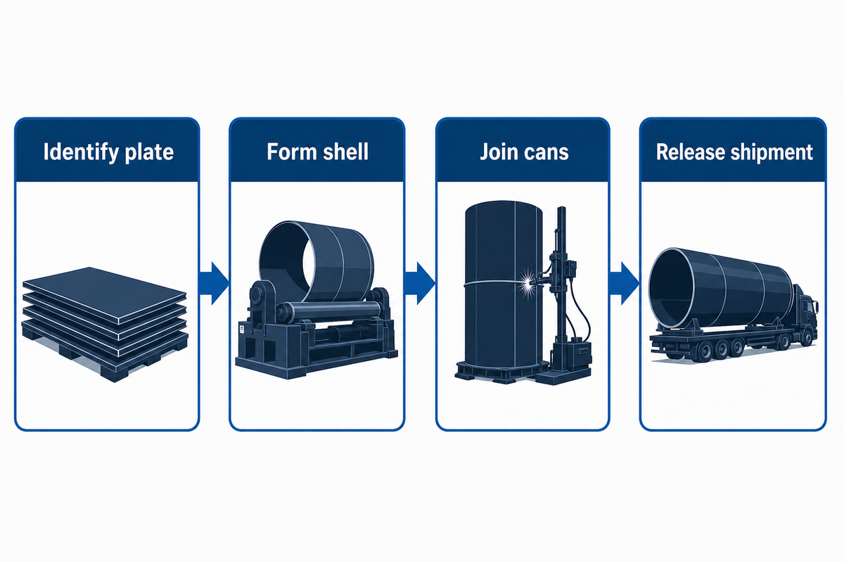
Steel plate is identified, cut, rolled into shells, welded into cans, and combined into transportable sections. The fabricator examines the required welds and dimensions, and the surfaces are prepared and coated. The section is released for shipment. Factory route changes affect the order or equipment; handoff records must follow the approved project requirements.
| Handoff | Input | Output to identify | Evidence to ask for |
|---|---|---|---|
| 1. Receive | Specified plate | Plate or heat ID | Purchase specification and material record |
| 2. Cut | Approved blank drawing | Cut blank and edge ID | Cut/edge check |
| 3. Roll | Identified blank | Shell or can ID | Geometry check |
| 4. Longitudinal weld | Fitted shell | Closed can | Procedure, operator and seam record |
| 5. Circumferential weld | Identified cans | Longer section | Fit-up and seam record |
| 6. Inspect | Fabricated section | Accepted or held section | Examination, dimensions and repair closure |
| 7. Coat | Released surfaces | Protected section | Preparation and coating inspection |
| 8. Dispatch | Protected section | Shipped load | Release and load-out record |
The plant example in African Fusion at DCD Wind Towers demonstrates how handoffs were made tangible. Individual cans were identified, connected on growing lines, inspected and repaired if needed, and prepared for shipment. This example demonstrates what happens at one facility, and isn’t to be used as a template for all tower design. A government example for a spiral-welded alternative demonstrates the reason the approach isn’t universally valid. The production sequence for the remaining examples can be found in Aubrik’s nine-step production-line guide.
During the design boundary, the tower structure carries wind load from the turbine through its interfaces. Wind conditions and tower height are in the engineer’s design basis; factory records demonstrate whether the fabricated tubular tower is in accordance with the design basis. Process-flow charts shouldn’t be substituted for structural design or a site-turbine installation plan.
Wind speed and the resulting actions belong in design process. In operation, the tower carries equipment at the top of the tower, so the drawings must reflect the capacity of the structure for its intended function. The production record must confirm adherence to the drawings; it can’t recalculate the engineer’s load case.
Buyer decision: ask the bidder to show the exact factory boundary on its process map. Equipment and factory quotes should be compared line by line. A bid that includes work beyond factory fabrication (e.g. foundations or site erection) can’t be compared line by line with a factory-equipment quote.
Receive steel plate and preserve material identity
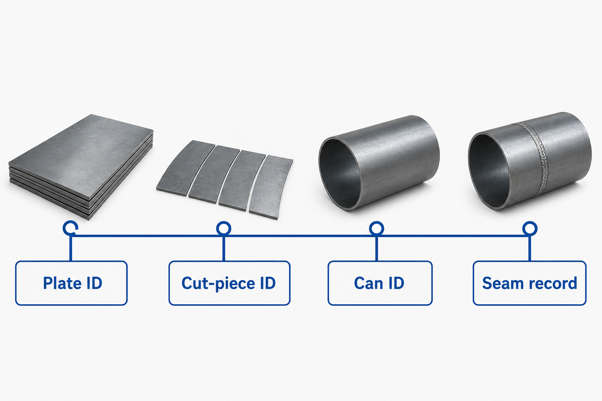
Identity is the first control. A plate certificate helps only if the plate, cut pieces and the later tower can be traced to the same approved purchase and drawing requirements. Ask the fabricator how the identifier is transferred to the cut pieces and tower can when the original markings are removed.
A usable traveler can carry the purchase specification, plate or heat identifier, drawing revision, intended section and receiving disposition. For this traveler, the buyer must decide which fields are mandatory under its contract. DCD’s published case says each can received a unique identifier before plate entered the facility; it doesn’t establish a universal certificate format.
If a batch includes multiple grades or thicknesses, request a sample trace. This means selecting one completed can and tracing its identifier back to the plate and forward to the seam records. A general statement that “traces are available” doesn’t prove what plate was welded into the can. Put unidentified material on hold, i.e. under the buyer’s approved disposition process.
Section labels should retain legibility during transport. Drawings should distinguish between wind tower segment and individual rolled cans, particularly if they’re stored in the same bay. That distinction protects a trace from a simple but expensive mix-up.
A one can trace should be the standard, not a bundle of certificates. Procurement can request this during a supplier evaluation, and quality can check that the plate, cut piece, and can ID are consistent before the next operation.
Cut and prepare the plate for shell rolling
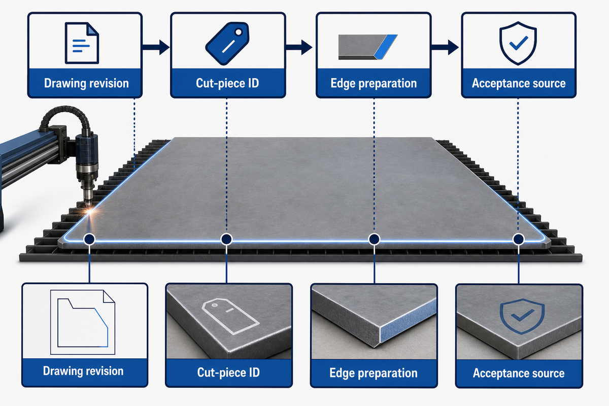
Cutting determines blank size and edge geometry for the shell. The work pack should show the approved drawing revision, the type of cutting, cut-piece ID, and any weld-edge preparation that follows. The edge check requires an acceptance source named other than a machine brochure. That source will specify the allowable bevels and fit-up for the buyer’s joint.
ISO 9013 specifies quality requirements for thermal cuts within its scope. It becomes relevant when the drawing or delivery terms invoke the standard and applicable edition; it does not create one wind-tower tolerance by itself. Confirm if thermal cutting is actually used before placing it on the check sheet.
Ask for the cut-piece ID, approved drawing revision, edge preparation, and the disposition of any rework. A downstream rolling operator shouldn’t need to infer which edge belongs to which joint. The named DCD example describes cutting and beveling before rolling, with different blanks for different conical cans; that is a case detail, not a universal machine setting.
A CNC cutting program requires the same revision as the traveler. If changes are made to the cutting parameter, note who approved the change, and whether the edge retains fit with the selected welding procedure.
A purchasing objection to resolve is: “The cutting station meets our thickness range.” This doesn’t mean the edge of the blank matches the welding procedure. A sample blank along with an inspection record for a thick and thin representative can should be requested.
Roll the plate into a wind turbine tower shell
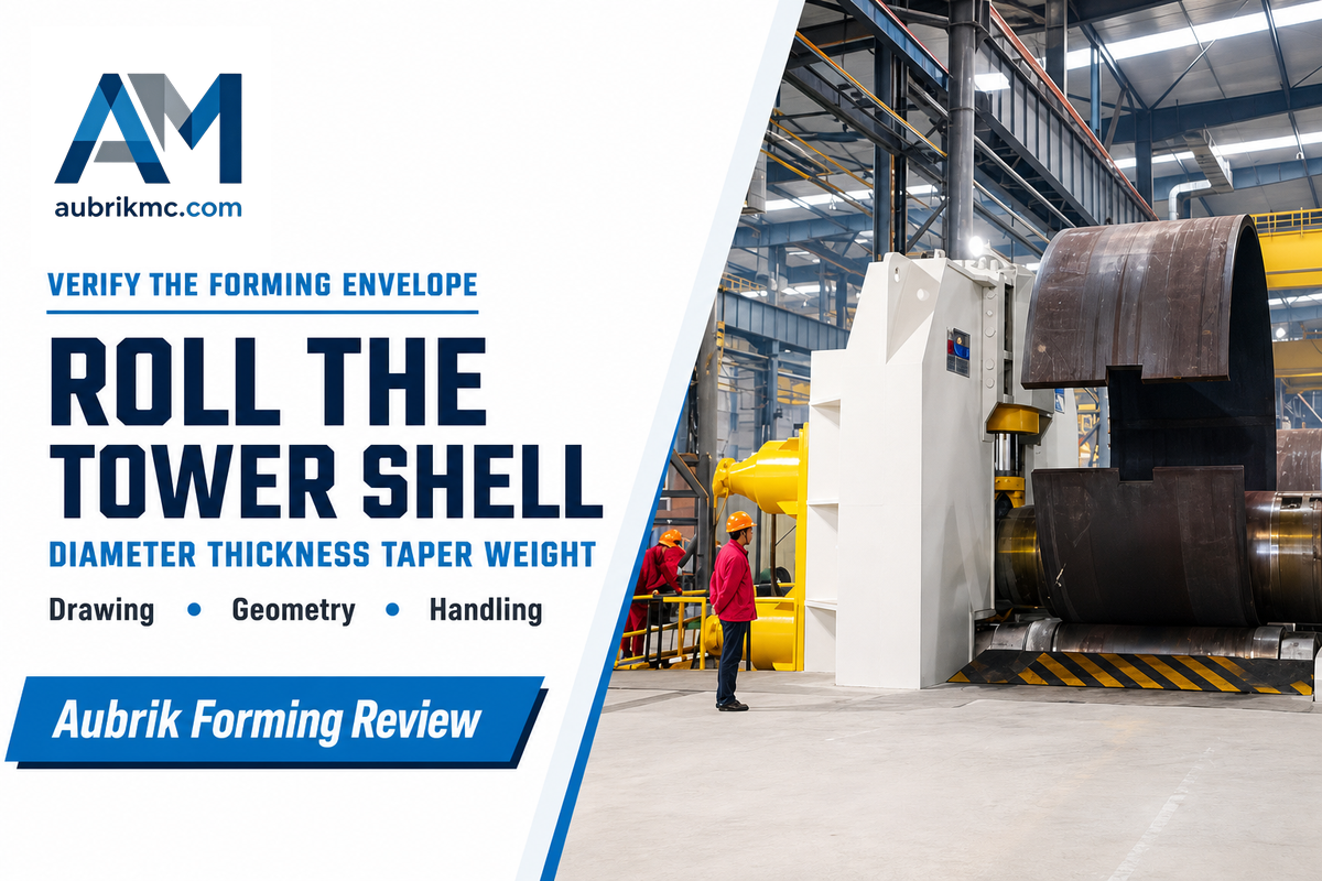
Rolling converts the cut blank into a cylindrical or tapered shell. For equipment selection, the shell’s diameter, wall thickness, taper and the material of the shell determine the equipment envelope. The approved drawing controls the dimensional acceptance. Record the measured geometry before closing the longitudinal seam; otherwise later correction may hide the point at which the shape changed.
How does wind tower manufacturing work after plate cutting?
As the developed plate enters the rolling station, it’s formed into a ‘can.’ Operators check edge alignment and geometry against the drawing. If satisfied, the joint is fitted and the can is sent to its approved welding process. Because the can retains the plate ID, dimensional and weld records can be linked to the shipping section.
A vendor’s maximum diameter alone can’t prove that a proposed roller handles a buyer’s full mix. Factors such as diameter, thickness, grade, taper, minimum and maximum working length, and handling weight should all be captured on a design envelope sheet. The vendor should also state which combination is verified, because the most demanding values need not occur on the same can. Factory acceptance testing should evaluate a representative case mutually agreed upon in advance.
Design and manufacturing teams should agree on the location of the shell measurement and how to handle a borderline result. Different manufacturing methods may form a large wind turbine tower, but this article’s worksheet applies to a rolled steel shell. A drawing callout, rather than an adjective such as “precise welding,” governs acceptance.
The manufacturing of wind tower sections also differs from blade work with composite materials. Production of large steel cans centers on forming and welding plate, while the manufacturing of composite airfoils belongs to a different process and evidence set.
The DCD Wind Towers plant account reported 16 mm and 38 mm plates in different sections, but those are its historical project values. They’re useful for showing why a mixed product envelope is important, but they aren’t recommended design limits for your tower.
Weld longitudinal seams, then assemble and weld tower cans
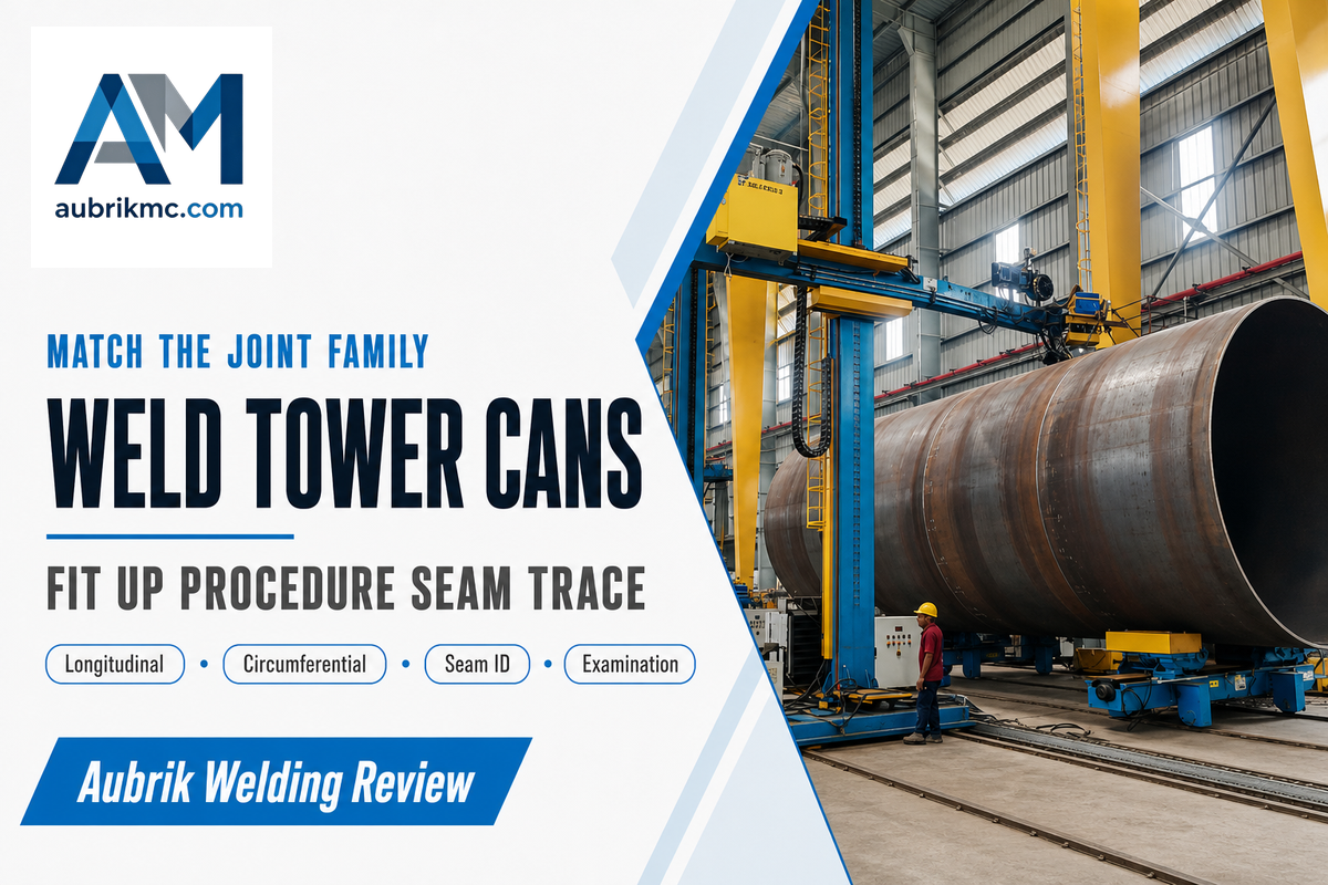
A longitudinal seam closes an individual shell. Girth seams connect cans to form a continuous shipping section. The two seam families dictate different positioning and access requirements, and so the production traveler should separately identify each seam, the approved welding procedure, and linked examination results.
| Joint | What it joins | Fit-up question | Record key |
|---|---|---|---|
| Longitudinal | Edges of one rolled shell | Are the edges aligned to the approved joint detail? | Can ID + seam ID |
| Circumferential | Two identified cans | Are orientation and gap controlled before joining? | Both can IDs + seam ID |
Which equipment joins tower cans into a section?
A line may use fit-up fixtures, turning rolls and welding manipulators to position and weld the girth joint. Select the equipment that best suits the purchaser’s needs based on diameter, weight, seam access and approved procedure and check the interfaces during an agreed trial. See Aubrik’s welding equipment guide and girth welder guide for more information.
Welding positioners and welding rotators cover handling. However, a rotator or welding turntable must be checked against the actual section load. Submerged arc welding may be one approved process, but the procedure qualification defines its scope. Seam welding records must define the specific joint and repair.
“We join and grow, join and grow until the tower is the required length.”
The two-row sketch doesn’t exhaust the weld inventory. Project-specific door openings, attachments and shell-to-flange welds need their own procedure and inspection entries where they exist. A published tower fatigue review identifies these details as relevant locations; it supplies no universal weld-examination percentage.
If one “tower weld” capability figure is used in a quotation, ask which seam and section mix it covers. A longitudinal seam trial can’t prove fit-up and travel performance at all the girth joints and opening details.
Fit flanges and interfaces to the approved section drawing
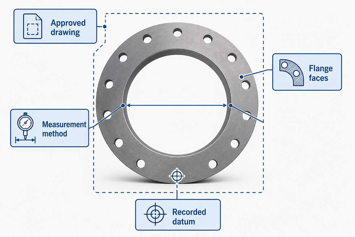
End flanges connect shipping sections and must match an approved section drawing before an assembly is released. Note the faces, method of measurement, definition of flatness and alignment on the drawing, and any approved corrections. Keep the factory flange operation separate from site assembly and bolting.
A study found that divergence in flange flatness changes the response of bolts in the modeled conditions. This indicates that geometry should be analyzed as a design and a fatigue concern, however, the study doesn’t provide a universal acceptance tolerance for all towers.
Contact the design authority for input on which interface dimensions are pertinent to this case and the location of the measurement report. If a vendor proposes to use a flange aligning station, request a demonstration that produces the same recorded datum and reports in the format that the buyer’s plan requires. “Accurate flange fit” in the absence of a measurement method isn’t an acceptance criterion.
The DCD case describes the flange measurement and straightening practice for a particular plant. Use the numbers as an example only for a historical project. The purchase specification and approved drawing govern the project at hand.
Inspect welds and dimensions against the project’s acceptance plan
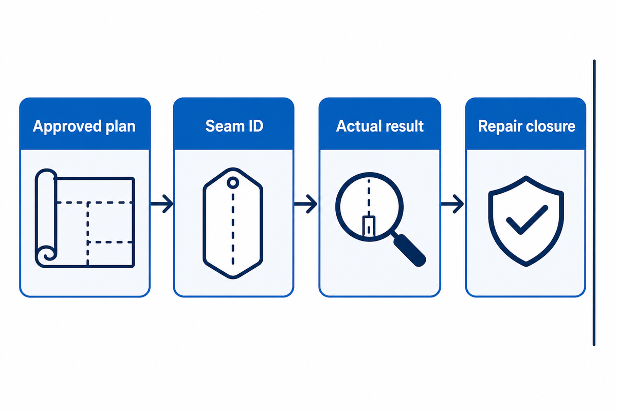
Each form of inspection and test answers a different question. An approved inspection and test plan (AITP) should name the joint or feature, method, examiner qualification, extent, timing, acceptance source and hold point. A stated percentage, by itself, in sales literature, doesn’t address these project choices.
How does a supplier show that a tower weld has passed inspection?
Provide the approved procedure, joint map, examiner’s qualification, actual result linked to the seam ID, closure of repair and retest. The record must show that the examination was performed after the required waiting interval. TWI’s work on delayed hydrogen cracking provides an explanation of the rationale for the approved timing for susceptible ferritic welds; it doesn’t establish a single, universal number of hours.
If the approved plan is for ultrasonic examination, the report must name the instrument, location and examiner, and provide the acceptance level. The statement “The weld was tested” doesn’t indicate what was examined or if the approved timing was observed.
ISO 3834-1 addresses selection of fusion-welding quality requirements, while DNV-ST-0126 can be a structural-design contractual reference. Neither publisher page is a signed acceptance record for this section. The governing edition, examination extent and acceptance level need to come from the applicable project documents.
Some projects require external verification roles by law or permit conditions. For applicable US federal offshore projects, 30 CFR 285.708 -709 addresses fabrication review by a certified verification agent or an approved project engineer. The roles can be alternatives where an exemption is approved; the project documents identify which role applies. Verify the scope and jurisdiction, rather than presuming a buyer’s signature is the sole release authority.
An offshore wind turbine may face a different verification route from an onshore tower. The buyer should name the applicable offshore wind energy project requirements, before a fabrication record is used as release evidence.
A clean report with the wrong seam ID, method, timing or acceptance source is not useful evidence. Direct quality staff to reconcile such discrepancies before coating closes access to the joint, and hold unresolved repairs in an explicit hold.
Prepare, coat and transport the released section
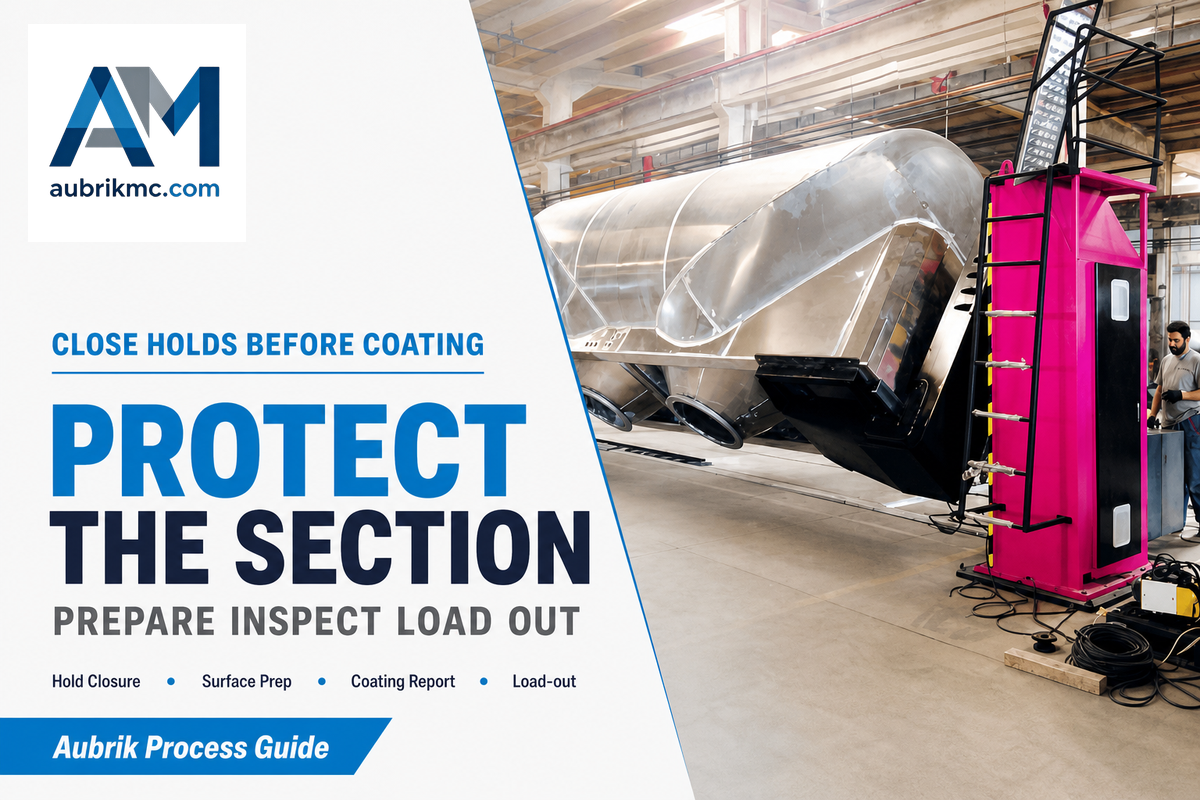
Coating should begin after the fabrication and inspection hold points that must precede it. The project coating specification defines the conditions of the surface to be coated, the method of surface preparation and paint system, the exposure environment and other conditions and factors which may affect the durability of the coating, and inspection. The load-out plan then addresses protection, lifting and transport interfaces for the actual section.
ISO 12944-5 describes protective paint systems within its stated environmental scope. It excludes some exposure categories from that part; a reference to “ISO 12944” alone does not identify the right system for every offshore zone. Ask for the named category, applicable part, and edition before comparing coating system proposals.
A DCD plant account describes washing, blasting, coating, final inspection and load-out. These operations illustrate a factory route. Other structural and fabrication approaches, including documented spiral-welding routes, may relocate or alter work packages. Record the actual shipment boundary in the quote.
A quoted coating “life” or thickness without the project environment and inspection method isn’t a release rule. Request preparation and coating reports, approved repairs, handling protection and the signed load-out handoff.
Build the 8-Record Tower-Section Release Packet
The 8-Record Tower-Section Release Packet is an editorial worksheet for a buyer and fabricator to complete together. It groups documents by decision, not by file type. The DCD Wind Towers plant account describes a unique identifier for each can; these record groups remain this article’s editorial worksheet, not a claim that DCD mandated this exact pack. The buyer’s approved drawing, specification, inspection plan and applicable law decide which individual records are mandatory. An empty field below doesn’t become acceptable just because a brochure lists the process step.
| Record group | Responsible party | Acceptance source to enter | Evidence file / ID to enter | Disposition |
|---|---|---|---|---|
| 1. Material identity | Fabricator / buyer quality | Purchase specification | Plate-to-can trace | Release / hold |
| 2. Approved design | Design authority / buyer | Drawing revision | Approved drawing list | Release / hold |
| 3. Cutting and edges | Fabricator | Drawing and invoked cutting requirements | Cut-piece / edge report | Release / hold |
| 4. Rolling and geometry | Fabricator quality | Drawing-defined dimensions | Can / flange measurement report | Release / hold |
| 5. Welding and seam trace | Welding coordinator | Approved procedure and qualification scope | Procedure, operator, seam map | Release / hold |
| 6. Examination closure | Quality / external verifier if required | Approved plan, law and acceptance level | Results, timing, repair/retest closure | Release / hold |
| 7. Coating release | Coating quality | Project coating specification | Preparation and coating reports | Release / hold |
| 8. Load-out handoff | Fabricator / logistics / buyer | Transport and release plan | Protection, lift and dispatch signoff | Release / hold |
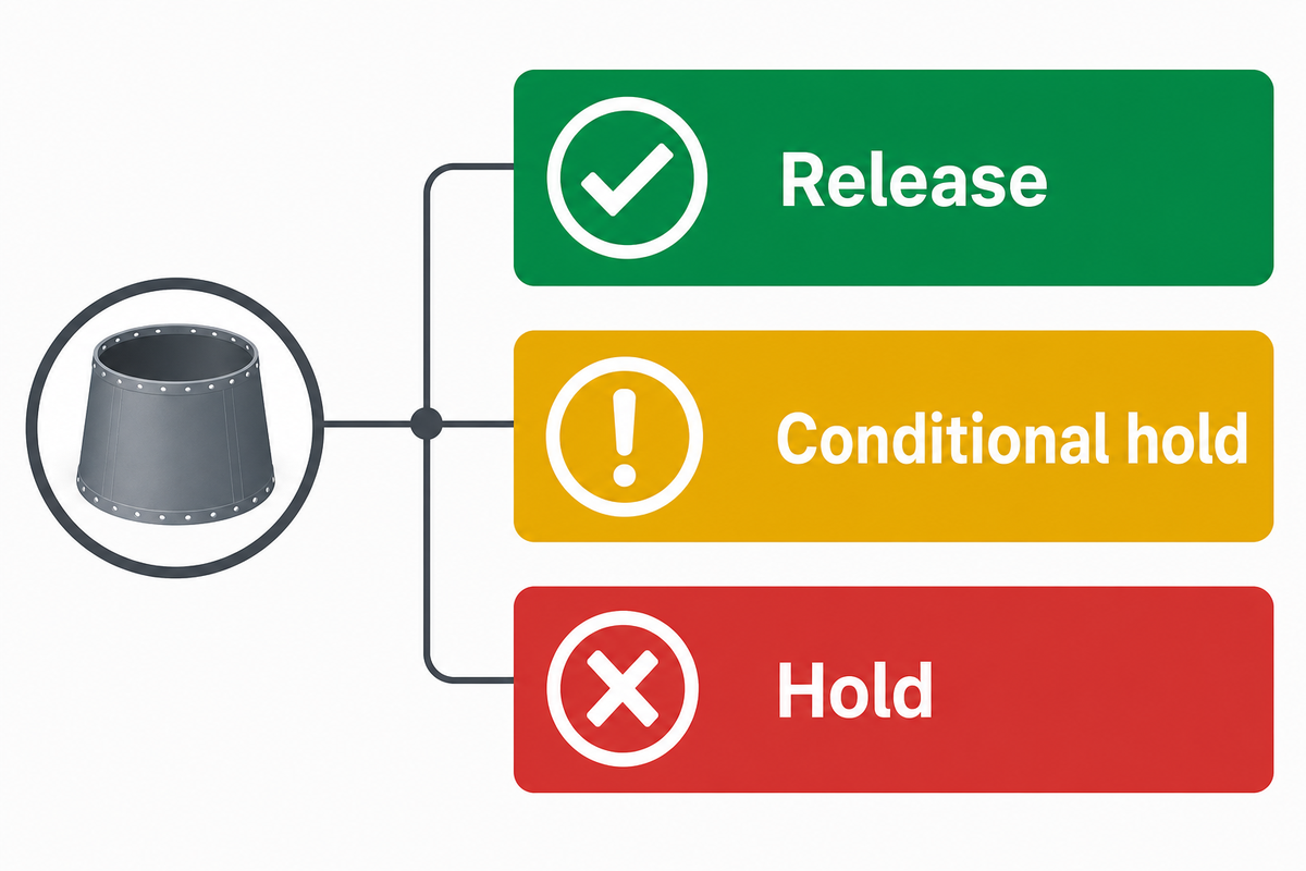
Use three decisions: Release when all mandatory evidence is accepted; conditional hold for a noncritical item with a named owner and agreed disposition; and hold when a mandatory criterion or required verifier signoff is missing. The packet can’t waive an approved hold point. Identifiers for the attached documents should be used, rather than accepting numbers from a different project.
This worksheet alters the handoff conversation. It shows procurement what was promised; it illustrates for quality the acceptance sources and controls; and it reveals for the plant manager what stops dispatch. The eight rows are record groups, and aren’t meant to suggest a project requires exactly eight documents.
Check production-line integration and utility requirements
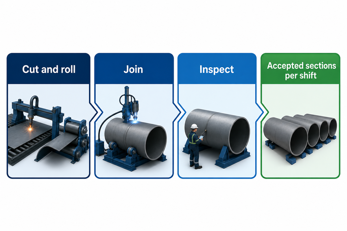
Equipment selection is based on the buyer’s tower mix and measured station cycle times. The Measured Bottleneck and Line-Design Input Sheet keeps nominal welding speed separate from accepted sections per shift. A line can move a queue from welding to fit-up or examination; or repair and coat; or transfer; measure the present queue before guaranteeing an output increase.
| Input to fill | Buyer baseline | Supplier proof requested |
|---|---|---|
| Diameter and wall-thickness range | Min/max by drawing | Verified operating envelope |
| Grade, taper and section mix | Share of actual orders | Representative trial pieces |
| Can and section handling weight | Maximum lift and transfer route | Rigging and equipment limits |
| Cut and rolling cycle | Minutes per accepted can | Trial cycle and rejection log |
| Fit-up and weld cycle | Minutes by joint family | Witnessed joint trial |
| Examination and repair cycle | Queue time and retest rate | Inspection interface plan |
| Coating and load-out | Wait time and route constraint | Downstream interface layout |
| Power, controls and footprint | Site drawings and available utilities | Utility and layout drawings |
| Accepted sections per shift | Measured product-mix baseline | Agreed acceptance-test result |
A 2025 study of one tower plant models lead-time dependence between production stations. While it can help measure sequence, it can’t help predict another plant’s output. DCD’s published discussion on balancing and joining, which is also plant specific, is likewise an example. A finance reviewer can compare the price of an integrated line with separate stations only after the plant provides its own queue, scrap, rework and labor.
Welding automation should be compared against the entire fabrication process. The baseline should include time spent moving workpieces, waiting for examination and closing repairs. Production efficiency should likewise mean more accepted sections of the line released under the same rules; a shorter arc-on time doesn’t always mean increased productivity and safety.
Manufacturing wind tower sections for power generation is a flow problem: cutting, rolling, joining and inspection share the output target. The production of wind tower sections should therefore be quoted as accepted units under an agreed product mix, not merely as nominal weld travel speed.
There are hidden bottlenecks in the system; map them before adding automation. After commissioning, test the same product mix and acceptance rules again. Faster deposition is helpful only if fit-up, examination and dispatch allow more accepted sections through the entire route.
Ask the supplier for proof matched to the buyer’s tower designs

A line vendor has evidence of the capability of the equipment. The tower fabricator owns the section’s material, weld, examination and coating records. The buyer and design authority have the approved acceptance basis. Maintaining these roles makes a request for quotation testable and differentiates a certified tower from the machine capacity.
Send the supplier a drawing envelope and the filled out line input sheet. Request a layout, capacity calculation with assumptions, verified weight and geometry range, welding-process boundary, lifting and utility drawings, inspection interfaces, factory acceptance-test plan, service/spares plan and exclusions. Ask who witnesses the trial and what evidence will count as acceptance for the buyer’s actual product mix.
Aubrik publicly offers wind tower production-line equipment. An offer isn’t independent evidence of accepted sections per shift at a customer’s plant. For more information about the company, visit the About Aubrik page.
Request a line configuration review. Bring the diameter/thickness envelope, section mix, station baseline and acceptance plan. Discuss your wind tower production line with Aubrik.
Frequently asked questions
What is the wind tower manufacturing process for a tubular steel section?
Specified steel plate is identified, cut and prepared, rolled into shells, welded into cans and joined into a transportable section. Project-required examinations and dimensional checks follow the approved inspection plan. The section fabricator then performs and records the coatings and closes records, and releases the section for shipment. The order of operations and acceptance criteria varies according to the design, contract and route.
How is a wind tower production line different from tower installation?
At the factory, the production line works on plates, shells and shipping sections. Site work starts with delivered components and works from an erection plan for the tower and other turbine components. Purchasing factory equipment doesn’t establish installation capability. Separate scopes, drawings and acceptance evidence must be provided for each activity, especially when the supplier proposal uses the word “complete.”
What should be checked before buying a complete wind tower production line?
Work with the approved drawing range for the tower, required steel grades, section mix, and weld methods, and specify lifting weights and an inspection plan. Include cycle-time, footprint, power and control interfaces, coating constraints, and dispatch limitations. Have the vendor identify which stations perform which operations and describe how a witnessed test will define and measure acceptance to the buyer’s specification.
Is there a universal inspection percentage for wind tower welds?
No single percentage can be taken from this article for every tower project. Inspection extent, method, timing and acceptance level follow the applicable design, contract, approved procedures and any governing law or external verification requirement. Ask for a seam map and specific inspection and test plan for the project before accepting a general sales claim.
When should coating begin on a tower section?
Coating follows the requirements of fabrication and inspection hold points. The coating specification governs surface preparation, environment, system, application and inspection. If a weld repair remains open, determine the status before restriction of access by coating. There are no universal values of film-thickness or coating route for all towers.
References & Sources
Sources were checked on 13 October 2026. Publisher pages describe scope, and the DCD account describes one named factory. Project documents control final acceptance.
- African Fusion: DCD Wind Towers fabrication account.
- U.S. Department of Energy: spiral-welding tower route.
- DNV-ST-0126 publisher scope; IEC 61400-6 publisher record.
- ISO 3834-1; ISO 9013; ISO 12944-5 publisher records.
- University of Seville repository: tower plant lead-time research; tower fatigue review; flange flatness fatigue study.
- TWI: delayed hydrogen-crack inspection research; U.S. Code of Federal Regulations, 30 CFR 285.708–709.