Get in Touch with Aubrik Company

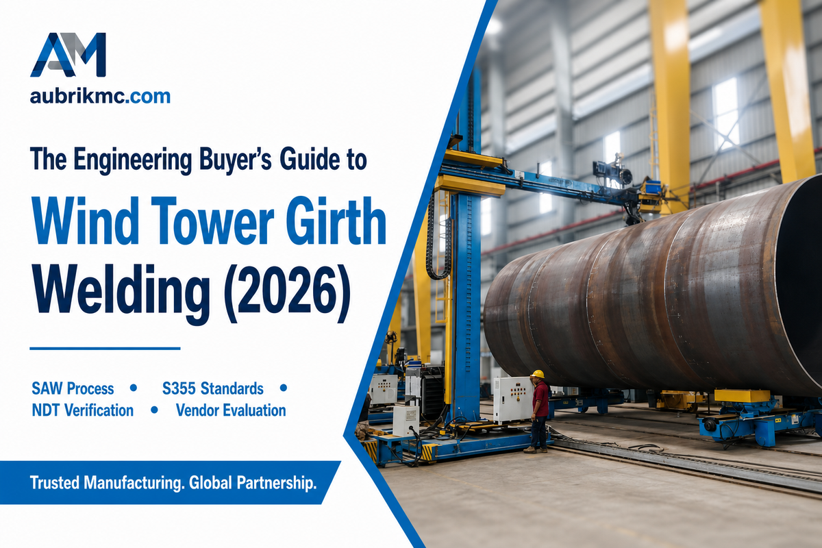
A wind tower girth welder is the automated machine that fuses rolled steel tower sections into a complete cylinder with a single circumferential seam, and choosing the right one – or even the right welding process – depends on wall thickness, steel grade, and where the tower will spend the next 20-25 years. This guide walks through the process technology, the standards a fabricator has to satisfy, why manual circumferential welding breaks down at production scale, and what to actually ask a vendor before signing a purchase order.
A wind tower girth welder automates the circumferential (girth) seam that joins rolled steel “cans” into a finished tower section, usually pairing submerged arc welding with a powered rotator. Automated lines report defect rates below 1% versus 8-12% commonly cited for manual circumferential welding, and cut section cycle time from roughly one section every two shifts to several per shift. The equipment choice, however, matters less than the welding procedure and steel-grade qualification behind it.
Key Points
- Submerged arc welding (SAW) dominates wind tower girth seams because it delivers high deposition rates on plate up to 80 mm thick – but a 2026 hybrid laser-arc process now claims a 2.9x reduction in weld volume for the same joints.
- Every genuine competitor selling girth welders repeats an identical, unattributed “~40% faster” claim with zero cited methodology – treat that number skeptically, not as fact.
- Wind tower girth welds answer to more than one standard: ISO 15614-1 qualifies the welding procedure, but DNV-ST-0126 governs the support structure itself.
- More automation doesn’t automatically mean proportionally lower cost – published research on wind tower fabrication economics found productivity gains don’t always translate into profitability gains.
- Offshore towers generally use thicker, tougher steel grades and require a post-weld hold time before inspection to catch delayed hydrogen cracking – onshore procedures rarely need this step.
Quick Specs: Wind Tower Girth Welding
| Typical process | Submerged arc welding (SAW), single- or multi-pass |
| Common wall thickness | 6.5-80 mm (onshore); up to 80 mm+ offshore |
| Common steel grades | S355N/NL (onshore); S355K2/NL (offshore, lower-temperature toughness) |
| Procedure qualification | ISO 15614-1 (Process 12 = SAW) |
| Weld quality reference | ISO 5817:2023 (current edition — 2014 edition withdrawn) |
| Common NDT methods | Ultrasonic testing (UT), radiographic testing (RT), magnetic particle testing (MPT) |
What Is a Wind Tower Girth Welder?

A wind tower girth welder is an automated welding machine built to fuse rolled steel tower “cans” into a completed section with one continuous circumferential weld. Rather than a person walking or standing on a rotating structure feeding an electrode by hand, the section itself rotates on a powered rotator or turning-roll system while a fixed welding head – almost always submerged arc – lays a consistent bead around the full circumference.
On a 70-90 m tower, several of these girth welds stack up to hold the whole structure together against decades of wind load and thermal cycling. In practice, a single 80 mm thick S355 girth seam can take a skilled crew multiple shifts to complete by hand, versus a few hours on an automated line – the kind of gap that shows up directly in a fabrication shop’s delivery schedule.
It’s not a wind tower thing; girth welding – connecting two cylinders along their joint circumference – is the very same joint used in storage tank fabrication, and many of today’s automatic girth welders merchants cut their teeth in tank-building, back before the industry discovered it could monetize wind, and they know where the 3 o’clock welder comes from. Wind tower fabrication is still a comparatively young manufacturing segment by that measure – NREL’s own supply-chain analysis treats it as a distinct capability fabricators have to build up, not an automatic extension of tank or pipe experience. This same automatic girth welding (AGW) equipment category, in fact, serves well beyond wind towers: pressure vessels, large storage tanks, petrochemical reactors, and shipbuilding all rely on the same welding method to join rolled cylindrical shell plate into a finished vessel. A tank welder building a water treatment tank and a wind tower fabricator running a girth weld on a 4-meter can are working comparable production schedules on structurally similar equipment, even though the end markets look nothing alike.
What Manual Girth Welding Actually Costs You
Manual circumferential welding relies on single-person consistency for the entire 15 to 25 m of a joint. Equipment vendors and industry sources commonly report an 8-12 percent defect rate for manual circumferential welds – a figure worth treating as a directional industry estimate rather than an independently audited statistic, since it traces back to vendor case examples rather than a published standards body.
It’s usually driven by inconsistency in arc-on time, drift in torch angle as the operator’s position relative to the joint changes, or fatigue over a multi-hour pass. Automated girth welding removes that human-consistency variable – not the engineering judgment behind the weld procedure, which still has to be right before the machine ever strikes an arc.
Welding Process Technology: SAW vs Manual vs Emerging Alternatives

The 3-Process Selection Compass
Comparison table of the three process families a wind tower fabricator chooses between, vs wall thickness vs production volume.
Submerged arc welding (SAW) is standard for wind tower girth seams for an engineering reason – not industry convention: Because of its enclosed arc and the large number of filler metals that can be deposited, SAW works efficiently for heavy structural steel plates that would require significantly more manual passes to fill the joint. Lincoln Electric consumable engineers Sev Johansson and Patric Wahlen describe SAW as capable of handling wind tower plate as thick as 5 inches (127 mm), with the flux-and-wire combination – not the arc alone – ultimately determining weld toughness at the cold temperatures wind towers experience in service. Peer-reviewed research published in 2026 in Optics & Laser Technology treats narrow-gap SAW as the established baseline process for exactly this thickness range, which is precisely why its authors frame hybrid laser-arc welding as a challenger to SAW rather than a replacement for some other method. That equipment and process investment is exactly the kind of capability gap NREL’s supply-chain roadmap flags as a barrier for fabricators new to wind tower work.
| Process | Typical wall thickness | Deposition rate | Best fit |
|---|---|---|---|
| Submerged arc (SAW) | Up to 80 mm | High | Shop-based circumferential production welding |
| GMAW / FCAW | Under ~20 mm, or field repair | Medium | Thinner sections, portable field setups |
| Manual SMAW | Any (not recommended at scale) | Low | Repair welds, tack welds, non-production runs |
An open-access 2026 study in Optics & Laser Technology (Gook, Biegler, Gumenyuk, and Rethmeier) suggests where the process technology is next headed, that of combining hybrid laser-arc welding (HLAW) for the first pass with narrow-gap SAW for the fill passes on 80mm S355ML plate. It reduced weld volume and filler consumption 2.9-fold and completed the joint in 12 layers versus the 42 layers that a conventional SAW joint prep would require, and Charpy V-notch impact tests at -40 C were still 65-274 J over the weld zones – comfortably within the toughness wind towers need in cold offshore service. It’s not yet a commodity purchasing decision the way SAW is, but it means that the statement “SAW is the only real option for 80mm steel” isn’t going to remain true forever.
Most conventional SAW-based girth welders also carry a flux recovery system – vacuum and filtration hardware that reclaims unused flux for reuse, since flux is a real consumable cost over the same 15-25 m circumferential pass discussed earlier. Vendor-claimed recovery rates commonly cited in the 70-80% range should be verified against your own wire/flux consumption records rather than taken at face value. Equipment generally comes in single-sided and double-sided AGW configurations: a single-sided machine welds one side per rotation, while a double-sided setup welds the inside and outside of the seam simultaneously for higher-volume production runs. Neither configuration is automatically “better” – it depends on your section thickness and whether internal access is even possible on your tooling.
How Girth Welders Fit Into a Wind Tower Production Line

A girth welder on its own does nothing – it needs something to hold the tower section still and rotate it at a controlled, repeatable speed while the welding head stays fixed. That job belongs to a welding rotator or turning-roll system, and on many lines a column-and-boom welding manipulator positions the head itself for internal seams or awkward-access joints.
Buyers sizing out a full wind tower production line are really specifying three or four pieces of equipment working in sequence, not one machine – the same multi-equipment reality NREL’s supply-chain roadmap describes when it discusses the rolling, welding, and handling equipment a new tower line requires together.
This is also where a lot of first-time buyers underestimate scope. A rotary welding positioner sized for a 3-meter onshore can will bind or under-power on a 7-meter offshore section; a welding turntable rated for the wrong load class becomes the line’s bottleneck no matter how fast the girth welder itself can run.
If you’re speccing rotation equipment for the first time, our guide to welding rotators and turning rolls covers load-capacity sizing in more depth than fits here.
Materials, Standards and Weld Procedure Qualification

📐 Engineering Note
Before any production girth weld is struck, the fabricator’s welding procedure specification (WPS) has to be backed by a procedure qualification record (PQR) tested to ISO 15614-1 (arc and gas welding of steels – Process 12 covers submerged arc).
That qualification is joint-specific: material grade, thickness range, and joint geometry each sit inside a qualified range, not a blanket approval for “SAW on steel.”
Wind tower fabrication most often uses S355N/NL structural steel for onshore towers and S355K2/NL for offshore sections, where the “K2” designation reflects better low-temperature impact toughness – a real requirement, not a nice-to-have, given offshore towers see sustained low temperatures and constant cyclic loading from waves and rotor thrust. Weld-quality acceptance is judged against ISO 5817:2023 imperfection levels (B, C, or D) – worth double-checking with any vendor, since the prior 2014 edition of that standard was formally withdrawn and superseded.
Weld procedure qualification is only part of the compliance picture. DNV-ST-0126, DNV’s standard for wind turbine support structures, sits above the weld-specific standards as the contractual reference many buyers and certifiers actually specify – covering design, construction, installation, in-service inspection, and certification of the structure the girth welds become part of.
A fabricator can have a perfectly qualified WPS/PQR and still fail a project’s contractual requirements if the support-structure-level certification path was never addressed.
Why Manual Girth Welding Fails at Scale: A Defect Atlas

Manual girth welding fails at scale because a handful of root causes – inconsistent travel speed, torch drift, rushed interpass cleaning, and skipped preheat – repeat across every long pass a person welds by hand, and each one maps to a specific, recognizable defect type rather than random bad luck. Naming those failure modes is the first step to catching them before final inspection.
The Wind Tower Girth-Weld Defect Atlas
Four defect families that show up disproportionately in manual circumferential welds, with what causes each one and how it’s typically caught.
| Defect type | Root cause | Typical detection method |
|---|---|---|
| Lack of fusion / porosity | Inconsistent travel speed, arc length drift | Ultrasonic testing (UT) |
| Undercut / off-center bead | Manual torch positioning error over a long pass | Visual + radiographic testing (RT) |
| HAZ cold cracking | Insufficient preheat or cooling control on thick S355 sections | Delayed UT after hold time (see NDT section) |
| Repair-weld fatigue notch | Dissimilar repair procedure too close to the original weld | Magnetic particle testing (MPT) + fatigue re-assessment |
| Slag inclusion | Incomplete slag removal between SAW passes | Radiographic testing (RT) |
| Excessive weld cap reinforcement | Flux/wire combination not matched to joint design | Visual + profile gauge check |
| High-low misalignment at the joint | Section fit-up tolerance not held before welding | Visual + dimensional check pre-weld |
| Excessive HAZ hardness | Heat input outside qualified WPS range | Hardness testing (ISO 9015-1) |
| Distortion / residual stress | Unbalanced weld sequence on asymmetric joint | Dimensional survey post-weld |
You may easily overlook that last line if you’re framing girth-weld quality purely in “manual vs. automated” terms. According to a 2026 Springer study examining the fatigue performance of repair welds in girth-welded S355 tubular structures, existing fatigue-design standards offer little guidance if the repair weld is located close to the original joint and was constructed with a different procedure than the original qualifying procedure – a situation having nothing to do with the original weld being manual or automated, but everything to do with how a repair is planned and documented years after the fabrication was constructed. A defect-free girth weld on day one isn’t a warranty of a defect-free repair five years later if the repair procedure and its proximity to the original seam aren’t considered as separate design items. Every defect type in the table above ultimately gets judged against the same acceptance ladder: ISO 5817:2023‘s B/C/D imperfection levels. Slag inclusion in particular is a recurring complaint among welders running multi-pass SAW on low-alloy steel – a discussion thread among practicing welders on Eng-Tips describes exactly this problem showing up as small slag pockets between passes when interpass cleaning is rushed.
Offshore vs Onshore: How Wall Thickness and Corrosion Change the Weld Spec

✔ Onshore
- Typically S355N/NL, 6.5-60 mm wall
- Standard ambient-condition preheat
- Fewer corrosion-allowance requirements
⚠ Offshore
- Typically S355K2/NL, up to 80 mm+ wall for low-temp toughness
- Controlled preheat + post-weld hold time before NDT
- Corrosion allowance + coating/blasting sequencing built into the fabrication plan
NREL’s supply-chain roadmap for U.S. offshore wind notes that offshore towers commonly use plate in the 1- to 3.5-inch range, and that standing up this capability takes genuinely different staffing, training, equipment, and yard logistics than an onshore tower line – not just thicker steel on the same setup. Fabricators moving from onshore to offshore towers are taking on a plant-level readiness project, not just a procedure-qualification exercise.
Consider the first-time offshore qualifications for a 7.5 m diameter, 70 mm wall S355K2/NL section; Preheat temperature, interpass temperature control, and the wait period prior to ultrasonic testing must all be verified together as a single, qualified procedure. Using a previously qualified S355N/NL procedure at a different wall thickness would be precisely the sort of risk that a procedure-qualification record is designed to eliminate.
NDT and Weld Quality Verification
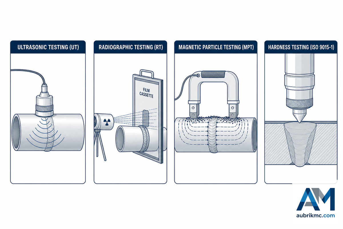
The 4-Method NDT Verification Field Manual
What each common post-weld inspection method checks for, and when it applies.
| Method | Detects | When it’s typically specified |
|---|---|---|
| Ultrasonic testing (UT) | Internal defects: lack of fusion, porosity, cracking | Standard volumetric check, thick-wall sections |
| Radiographic testing (RT) | Internal defects, weld profile | Where UT access is limited or code requires film record |
| Magnetic particle testing (MPT) | Surface-breaking cracks | Post-repair welds, surface QA pass |
| Hardness testing (ISO 9015-1) | Excessive HAZ hardening | Thick-section, high-strength steel qualification |
Many standards require a significant hold period-up to 48 hours in some cases-following welding prior to final volumetric non-destructive testing for hydrogen-sensitive S355 materials used for thick-wall offshore joints. This is to give delayed hydrogen-assisted cracking an opportunity to manifest in the material; a joint passing UT six hours after welding isn’t the same quality claim as a joint passing UT 48 hours after welding, even if the ultrasonic result look identical – both are being checked against the same ISO 5817:2023 acceptance levels, but only one of them had time to reveal a real problem. Radiographic inspection tooling continues to evolve here too – one recent patent describes a directional X-ray source built to insert directly into a rotating pipe or tower section for in-line girth weld inspection, rather than moving the part to a fixed inspection station.
“A girth welder doesn’t replace the engineering judgment behind a weld procedure, it replaces the variability of a person maintaining that same procedure by hand for hours on a rotating structure. The metallurgy still has to be right before the machine ever strikes an arc.”
The Real Cost of Automation: A Throughput Worksheet
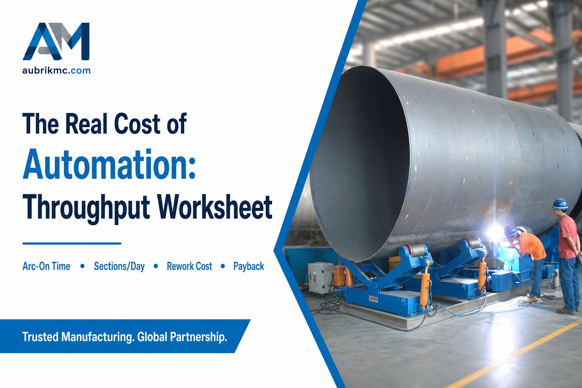
The Girth-Welding Throughput Worksheet
A vendor-neutral way to check whether automating your girth welding actually pencils out, using your own numbers instead of a vendor’s headline claim.
Almost every girth welder vendor website features one iteration of a round number or two: one promises “40-50% increase in welding productivity”; another “reduced fabrication time by up to 40%”; and yet another “40% cut in field storage tank welding time.” Three unrelated vendors, three similar numbers, and zero documentation of methodology, baseline or a supporting study. None of which to say automation isn’t worth considering. It’s simply that the vendor’s general number is a proxy for your shop’s math, not the answer.
Vendor literature for this equipment category also leans on a familiar vocabulary – “welding solutions,” “automated welding systems,” next-generation “welding technology,” and promises of eliminating human error to produce consistent, X-ray quality welds every time. Some of that is fair: automatic girth welding genuinely does remove a lot of the variability that traditional manual welding introduces into a long weld seam, and a well-run automated equipment line can be more cost-effective than staffing an equivalent manual welding operation with the same power source and welding power output. But “production efficiency” and “high productivity” claims are only meaningful in the context of your own fabrication projects and production schedules – whether you’re supplying an onshore wind power project, an offshore wind power project, or simply the next wind farm’s tower order – not a generic spec sheet.
To get to an actionable math, you’ll need four shop-specific inputs:
Fill in your own numbers
- Your current arc-on time as a % of shift length (manual circumferential welding commonly runs 20-30%).
- Your current defect / rework rate and the fully-loaded cost of a rework cycle.
- Your loaded labor cost per welding-hour (wages + benefits + supervision share).
- Sections produced per shift today, and the shift-length capacity ceiling you’re actually hitting.
Multiply the arc-on-time gap by your shift length and labor rate, add the rework-cost savings from a lower defect rate, and you’ve a shop-specific welding time and payback estimate-not the vendor’s generalized claim. And per the NREL supply-chain findings, your math isn’t complete without a staffing line: Automating the weld cell won’t eliminate the need for a skilled operator, a technician knowledgeable of the seam-tracking system and (if moving into offshore work for the first time) the lead time required to hire and train for a capability previously not performed in-house. Published studies on wind tower production economics is clear on this, and if productivity in a service-heavy fabrication business is increased, that increase doesn’t necessarily lead to increased profitability.
Evaluating a Girth Welding System Vendor

The Girth-Welder Buyer Due-Diligence Playbook
Questions to ask any vendor – not just the one selling you the machine – prior to committing to a girth welding system.
- Do you have a WPQR (welding procedure qualification record) to ISO 15614-1 for my thickness and steel grade – not just a general capabilities statement?
- What’s your actual spare-parts lead time and onsite response SLA – not the marketing spec?
- Do you have documented experience with my specific wall thickness and steel grade, or would this be a first-of-kind for you?
- If I’m moving into offshore grade work, what are your support footprint and equipment setup regarding plate handling, coating/blasting, and port or rail access to my facility?
- What training do your systems require and how long does it take my team to be independent, qualified?
This due-diligence still applies whether you’re buying new, evaluating a used wind tower girth welder for sale, or simply trying to size up a machine you already run. Before you sign anything, ask for the actual wind tower girth welder manual – a real operator and maintenance manual, not a glossy brochure – since how thoroughly a vendor documents setup, calibration, and fault codes says a lot about how mature the equipment design really is. And confirm upfront how wind tower girth welder parts are sourced: locally stocked, or shipped from overseas with a multi-week wait.
These third and fourth questions will be more important than most buyers anticipate at this stage. According to the NREL analysis referenced earlier, offshore-capable fabrication is substantially different than traditional onshore fabrication – radically different plate-handling equipment, significantly deeper staffing levels, radically different port or rail logistics for transporting finished sections. A vendor’s honest answer to “have you actually built this before, at this thickness, for this market” is worth more than any productivity percentage on a spec sheet. For buyers evaluating adjacent capability, our contract metal welding services overview covers what to expect when sourcing fabrication capacity beyond the girth weld itself. If you’ve already scoped your equipment needs and want Aubrik’s own specification sheet for reference, our wind tower girth welder page covers the WT-GW-I/II model range in full detail.
Industry Outlook: What’s Changing in Wind Tower Welding

Buyer research behavior is the most telling evidence of where this market is heading, and it isn’t about the girth welder in isolation, but a general habit of researching the entire welding range as a set. Interest in line-integrating terms (tower welding, welding rotators, SAW equipment, circumferential welding) has trended slightly upward in aggregate over the past 12 months, while the popular, generic “wind turbine welding” term has trended downward in the same period. Interpreted plainly, that’s buyers performing more targeted research before they approach a vendor, not less overall category interest. If your 2026-2027 line purchase is in the cards, that means arriving at vendor conversations with your rotator, manipulator, and girth welder requirements pre-loaded against your largest planned section – not your current average. This matters in practice because a fabricator who waits until an order lands typically faces a real delay in manipulator and rotator lead time, and re-qualifying a WPS to ISO 15614-1 for a new plate thickness adds still more before a single girth weld gets struck.
On the technology front, the blended laser-arc or narrow-gap SAW development previously mentioned warrants focus specifically for maximum-thickness offshore works – it’s a research product for 2026 rather than a product currently available in our catalogs, but it indicates where thick-section process innovations will trend as offshore towers become ever larger. Girth welding isn’t the only production step under pressure to change, either: the U.S. Department of Energy has documented Keystone Tower Systems’ spiral-welding process as an alternative that builds a tower from a single coil of steel welded in a continuous helical seam rather than stacking and girth-welding discrete rolled cans – a genuinely different manufacturing bet, not a refinement of the girth-welding approach this guide has covered. Also, the NREL offshore wind power supply-chain report indicates that North American offshore tower fabrication equipment is most often imported – which shouldn’t just be dismissed as a cost issue, but rather a real consideration of investment planning – for any fabricator expanding new capacity rather than upgrading existing assets.
(Market size estimates for the broader arc-welding equipment set – regularly identified as being in the $6-17 billion range in scope, while those for arc-welding as a sub-set generally call for mid-single digit CAGR – are directional industry context only and not to be used to support any of the guidance above – they differ wildly between research groups and their assumptions.)
💡 Pro Tip
If the line purchase you’re planning for 2026-2027, size your girth welder, manipulator, and rotator in combination against your current heaviest planned section – not the current average – so the line doesn’t become the limiting factor on your first large offshore order.
Frequently Asked Questions
What is a wind tower girth welder?
View Answer
A wind tower girth welder is an automated welding machine that joins rolled steel tower sections with one circumferential (girth) weld running fully around the cylinder. It pairs a submerged arc welding head with a rotator or turning-roll system that spins the section at a controlled speed, so the seam gets welded in a single continuous pass instead of a string of manual arc strikes.
Is submerged arc welding always required for wind tower girth seams?
View Answer
No. SAW dominates for the higher deposition rate and contained arc needed for heavy structural steel, but some fabricators employ gas metal arc welding (GMAW) for lighter sections or field-repairs where mobility outweighs pure deposition rate. The choice of process comes down to wall thickness, joint access, and whether the weld is shop- or field-located.
How is a girth weld inspected after welding?
View Answer
Most procedures pair visual inspection with at least one volumetric NDT method – either UT or RT – to look for defects such as lack of fusion and porosity, coupled with MPT for surface cracks. Thick-wall offshore joints made of hydrogen-sensitive steel may also need a holding period after welding before volumetric NDT, to allow delayed cracking to manifest prior to acceptance.
What steel grades are used for wind tower sections?
View Answer
Mostly S355N/NL onshore; thicker offshore sections often move to S355K2/NL for better low-temperature toughness. Exact grade selection depends on wall thickness and the governing design code.
Do girth welding lines need positioners or rotators as separate equipment?
View Answer
Yes – the girth welder head alone doesn’t rotate anything. It still needs a rotator, turning rolls, or a column-and-boom manipulator to move the joint past it.
Why We Write This
Aubrik builds wind tower production line equipment, including girth welders, so we’ve a direct stake in this topic, which is exactly why this guide covers process alternatives, standards, and vendor-evaluation questions that go beyond our own product line. The defect-taxonomy and standards content here draws on published welding-procedure and materials-fatigue research, not internal sales material. Reviewed by the Aubrik welding engineering team.
References & Sources
- A Supply Chain Road Map for Offshore Wind Energy in the United States – National Renewable Energy Laboratory (NREL)
- Cost of Concrete Wind Turbine Towers Additively Manufactured On-Site – California Energy Commission
- ISO 5817:2023, Welding, quality levels for imperfections – International Organization for Standardization
- What’s New in ISO 15614-1:2017 – TWI (The Welding Institute)
- DNV-ST-0126, Support Structures for Wind Turbines – DNV
- Integration of Hybrid Laser-Arc and Narrow-Gap SAW for 80 mm Thick S355ML Steel Plates – Optics & Laser Technology (Elsevier, open access)
- Consumables Make a Difference in the Welding of Wind Towers – The Fabricator (Lincoln Electric)
- Assessment of Flaws in Pipe Girth Welds – TWI
- EERE Success Story: How Spiral Welding Is Revolutionizing Wind Turbine Manufacturing – U.S. Department of Energy
- Rotating Welding System and Methods (AU2021229209A1) – Google Patents
- ISO 9015-1:2001, Destructive Tests on Welds in Metallic Materials – Hardness Testing – Part 1: Hardness Test on Arc Welded Joints – International Organization for Standardization
Related Articles
- Cobot Welding: A Buyer’s Guide – vendor-neutral guide to collaborative robotic welding
- Robotic Welding Cell Guide – full-cell automation for structural steel welding
- How to Size a Pipe Welding Positioner Before You Request a Quote
- Heavy Duty Welding Positioner Selection Guide
- Welding Positioners and Turntables: Selection Guide