Get in Touch with Aubrik Company
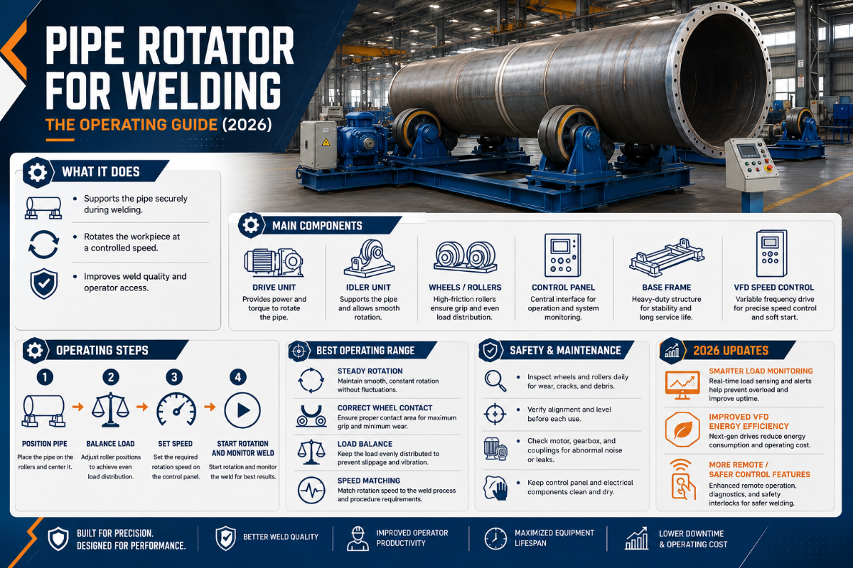
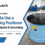
Pipe Rotator for Welding: How to Run Turning Rolls for Clean Girth Welds
Updated June 2026 · Reviewed by the Aubrik technical team
A pipe rotator for welding turns the work, not the welder. Set a pipe, spool, tank or pressure vessel on a powered wheel bed, dial a steady rotation speed, and a single welder lays a continuous circumferential bead in the flat position while the part rotates underneath the arc. What’s hard is not buying the machine — it is running it: matching roll RPM to your weld travel speed, setting the rolls up so the part does not walk, grounding a rotating workpiece without wrecking the bearings, and reading drift before it ejects a cylinder across the shop. This guide is the operating manual the spec sheets skip. Need capacity, type and sizing guidance? See the companion ABOKE pipe rotators for welding page; here we focus on how to operate one well.
Quick Specs — Pipe Rotator Operating Envelope
| What it holds | Long cylindrical work — pipe, spool, tank, pressure-vessel can, wind-tower section |
| Motion | Rotation about the part’s own horizontal axis (drive roll + idler roll bed) |
| Rotation speed | Stepless, typically 0.1–5 rpm on heavy sets (≈6–60 in/min surface speed) |
| Load capacity | 5–400 t across build tiers; size to the heaviest part + headroom |
| Processes | SAW, mechanized MIG/MAG, orbital TIG — anything that benefits from flat-position rotation |
| Weld type | Circumferential / girth seams; root, fill and cap in one continuous pass |
Pipe Rotators Under the Arc: Mechanism and Why It Beats Manual Rotation
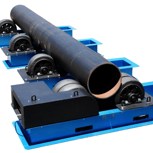
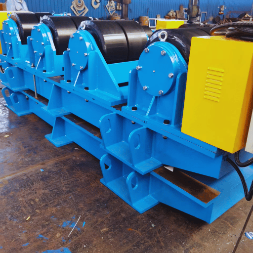
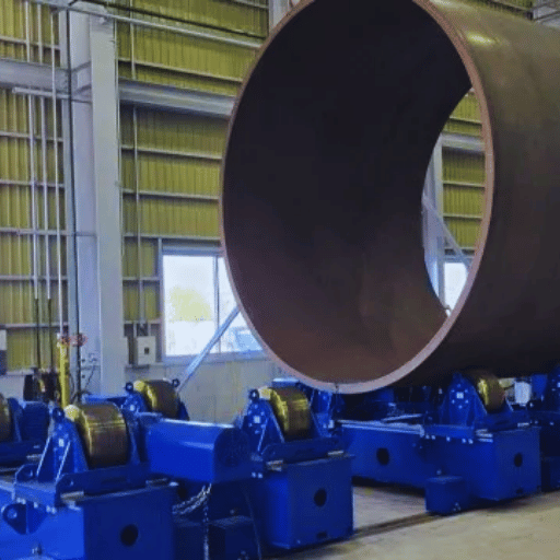
A pipe rotator — also called a set of welding turning rolls — is a powered drive unit plus one or more idler units that carry a cylinder and spin it at a controlled speed. Because the wheels carry the weight, the welder parks the torch at bottom-dead-centre and the joint comes to the torch turn after turn. That single change fixes a geometry problem: on a fixed pipe only a few inches of the joint sit at the ideal flat angle at any moment, and the rest forces the welder vertical or overhead, where gravity fights the puddle.
That payoff is weld quality, not just comfort. Every time a welder stops to crane or re-grip a heavy part, the restart is a place for porosity, undercut or an arc strike — and on a long girth seam there can be dozens of them. Continuous rotary welding removes the stop-starts: one welder runs the full circumference of a 24-inch spool or a 4-metre tank can without a second crane move. That is why pipe welding shops measure the gain in handling time and rework rate, not in arc-on minutes alone.
A rotator is one of three handling tools, and the operating logic differs. A welding positioner grips a compact part on a chuck or table and rotates and tilts it for multi-angle access; a manipulator clamps a balanced weldment between centres. A pipe rotator supports a long, heavy duty cylinder on a wheel bed and only rotates it — which is why it scales to far large and heavy work than any positioner chuck can cantilever. Full selection logic lives in the welding rotators and turning rolls overview; this guide assumes you have rolls and need to run them.
Compared to manual rotation, the operating case for this welding equipment is mostly welding productivity and cost: one operator instead of a crane crew, steady welding operations instead of stop-start handling, and lower labor cost per finished metre of seam. Shops book the increase efficiency as handling time removed per shift, plus the safety and efficiency gain of not craning heavy work overhead — and the lower costs that follow. That same family of fixtures serves different applications and different sizes: a benchtop-scale positioner handles a small flange, but pipe and vessel welding applications — and most pipe welding applications at production scale — need the wheel-bed rotational support a rotator gives.
The Travel-Speed → RPM Bridge: Setting Rotation Speed from Your WPS
The single most-asked operating question is “what RPM do I dial in?” The answer is not a fixed number — it is a conversion. Each roll has to move the pipe surface past the arc at exactly the travel speed your Welding Procedure Specification (WPS) calls for. Travel speed is a controlled, supplementary-essential variable under ASME BPVC Section IX, so the rotation speed is not a feel — it is computed from the joint diameter.
📐 The Travel-Speed → RPM Bridge
RPM = WPS travel speed ÷ (π × pipe OD) — keep length units consistent. Pipe circumference (π × OD) is the distance one full turn moves the surface; divide your required travel speed by it to get turns per minute.
Three worked examples you can re-run with your own numbers:
- ▪24 in OD, WPS 8 in/min: circumference = π × 24 = 75.4 in → 8 ÷ 75.4 = 0.106 rpm.
- ▪DN300 (324 mm OD), WPS 300 mm/min: circumference = π × 324 = 1,018 mm → 300 ÷ 1,018 = 0.295 rpm.
- ▪48 in OD, WPS 12 in/min: circumference = π × 48 = 150.8 in → 12 ÷ 150.8 = 0.080 rpm — which is why large diameter vessels need a stepless drive that resolves below 0.1 rpm.
| Pipe OD (in) | Pipe OD (mm) | RPM @ 8 in/min | RPM @ 12 in/min |
|---|---|---|---|
| 4 | 102 | 0.64 | 0.95 |
| 6 | 152 | 0.42 | 0.64 |
| 8 | 203 | 0.32 | 0.48 |
| 12 | 305 | 0.21 | 0.32 |
| 16 | 406 | 0.16 | 0.24 |
| 24 | 610 | 0.11 | 0.16 |
| 36 | 914 | 0.07 | 0.11 |
| 48 | 1,219 | 0.05 | 0.08 |
| 60 | 1,524 | 0.04 | 0.06 |
| 72 | 1,829 | 0.035 | 0.05 |
| 120 | 3,048 | 0.021 | 0.03 |
Surface-speed method; confirm travel speed against your qualified WPS. Need a one-click result? Use the ABOKE rotation speed and surface velocity calculator.
Why the math matters for weld quality: rotate too fast and the bead does not penetrate; rotate too slow and heat piles up in one place, warping thin wall or burning through. Because the RPM falls as diameter rises, a job that mixes a 6-inch spool and a 60-inch shell needs a true variable-speed drive — a fixed two-speed gearbox cannot hold surface speed across that diameter range.
Matching the Process: SAW, MIG and TIG on Turning Rolls
Rolls earn their keep fastest with high-deposition processes. According to a ScienceDirect engineering overview, submerged-arc welding (SAW) “is used primarily for welding vessel seams in the flat position… [and] requires turning rolls” — because the flux only stays in the joint when the seam is downhand. A pipe rotator keeps the seam parked in the flat position so SAW can run continuously, which is where the biggest cycle-time gain on heavy fabrication shows up.
Mechanized MIG/MAG gains too: a constant rotation lets a wire feeder with synergic control hold a steady stand-off and deposit a uniform bead, and manufacturers report meaningful productivity gains over hand rotation. Orbital and mechanized TIG ride rolls for thin-wall and root passes where welding precision matters more than deposition. Across all three, a foot pedal or wireless pendant lets the welder trim rotation on the fly without leaving the puddle.
How do MIG and TIG welding benefit from a rotary welding system?
Both processes benefit because the workpiece moves at a constant, repeatable speed while the torch stays fixed — so heat input per unit length is even all the way around the joint. For MIG on carbon steel or low-alloy pipe, that means consistent fusion and fewer weld defects at high deposition; the welder pairs synergic control with the rolls and a 500 amp class supply for heavy wall. For TIG, the steady rotation holds a tight, repeatable weld pool through the full circumference, which is what delivers the accuracy and consistency aerospace and instrumentation work demand. One operating note: stainless and nickel alloys shed heat poorly, so bump rotation speed up a notch versus the same wall in carbon steel to avoid discoloration and distortion.
On heavy-wall girth runs the arc typically sits near 300 to 500 A at 28 to 34 V while the rolls hold travel to the WPS window; drop rotation 10 to 15% for stainless to limit heat.
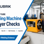
The 6-Check Roll Alignment Routine: Setup for a True Circumferential Weld
Industry field guides note that roughly 70% of turning-roll problems trace to setup mistakes, not equipment failure — so the setup routine is the highest-return operating skill on the floor. Run these six checks in order before the first rotation. This routine is the same whether you are rotating heavy reactor shells or short small pipe spools.
The 6 Setup Checks at a Glance
- 1️⃣Level the bed. Drive and idler frames sit level and co-planar; a bed on a sloped floor pushes the part to one end.
- 2️⃣Roll-height parity. Both roll sets matched in height within a few millimetres — the number-one self-inflicted cause of axial walk.
- 3️⃣Wheel-span to OD. Set the adjustable wheel span for the diameter so the part seats at roughly a 30–60° wheel-contact angle — not perched on top, not pinched.
- 4️⃣Seat and balance the load. Support the workpiece about 30–40% in from each end so the mid-span does not sag; the part should rest with equal contact, never wedged.
- 5️⃣Establish the ground path. Connect the welding return through a dedicated rotary ground, not through the wheel bearings (next section).
- 6️⃣Trial-rotate and mark. At the slowest speed, run one turn, confirm rotation direction, and chalk-mark the seam to watch for walk before you strike an arc.
📐 Engineering Note
Roll-height parity within ~2–3 mm across a 6-metre span is a practical target for heavy work. Verify rotation direction and electrical phase before loading anything heavy — a reversed phase spins the rolls backward on start-up. For capacity and idler-count sizing, defer to the pipe rotator capacity and type selector.
Grounding a Rotating Workpiece Without Arcing the Bearings
Here is the operating detail most guides skip. Welding return current — the ground — has to leave a part that is turning. If you let it find its own way through the wheel-to-shell contact and the roller bearings, the current arcs across the rolling bearing elements and pits the raceways. This is the same electrically-induced bearing damage (EDM fluting) documented in motor engineering, where uncontrolled shaft currents micro-weld and frost the bearing surface until it fails. On a rotator the cure is the same: give the current a low-resistance path that bypasses the bearings.
A ground brush rated for 300 to 600 A keeps the return off the bearings; even 1 V of stray shaft potential can pit a raceway over a 12 month duty cycle.
What is the role of the welding ground on a pipe rotator?
A welding ground closes the electrical circuit from the workpiece back to the power source so the arc is stable and the operator is safe (return-current practice follows AWS welding standards). On a rotating part it must do that through a sliding contact built for it — a copper-graphite brush or a dedicated rotary ground shoe riding the shell or the drive shaft — rather than through the load-bearing wheels. Specify the return method and your peak amperage on the order so the rotator is built with a brush rated for it; a 500 amp SAW job and a 200-amp TIG job want different contacts. Skipping this is invisible for weeks, then shows up as bearing noise and runout — a costly failure for the sake of a cheap brush.
The Creep–Slip–Track Fault Map: Diagnosing Drift, Slip and Walking
A common assumption is that a self aligning rotator removes every alignment headache. Field experience contradicts that: even a correctly set self-aligning roll can let the workpiece creep along its own axis, because the smallest roll-height difference or an out-of-round shell nudges the part sideways every turn. That anti-drift designs are patented — see USPTO US8342493B2 “Anti-drift turning roll system” and GB2106810A for longitudinal-creep compensation — tells you drift is a real operating variable, not something the wheels solve for free. Work the map below before you blame the machine.
| Symptom | Fault class | Root cause | Operating fix |
|---|---|---|---|
| Part walks toward one end | Axial creep | Roll-height difference; sloped bed | Re-level; match roll heights within a few mm |
| Walk on an out-of-round shell | Axial creep | Ovality changes contact each turn | Use self-aligning/anti-drift set; tack-round before welding |
| Wheels spin, part lags | Slip | Grease/oil film on wheels | Degrease wheel faces and shell contact band |
| Slip under off-centre load | Slip | Low wheel pressure / wrong wheel | Increase span angle; steel wheels for grip on heavy work |
| Slip near rated limit | Slip | Over-capacity load | Move up a tonnage tier; check the load rating |
| Seam wanders off the torch | Tracking | Part axis not parallel to roll axis | Square the part; add a seam-tracking guide |
| Mid-span sag, droop | Support | Long thin wall, no centre support | Add idler units / steady rest between drive sets |
| Wobble / runout grows | Stability | Unbalanced or bent part | Stop; re-centre; use emergency stop if it grows |
| One-sided wheel wear | Wear | Chronic misalignment / overload | Correct alignment; replace wheels as a matched set |
| Grinding noise, vibration | Drive/bearing | Bearing wear (often current pitting) | Inspect bearings; verify ground brush path |
“We check roll-height parity before the first rotation and run the welding return through a ground brush, never the bearings — those two habits kill most of the axial creep and the bearing failures customers blame on the wheels. On unbalanced shells we spec steel wheels with bearings, not rubber, because spatter eats a rubber face and a re-wheel costs more than the job saved.”
— Aubrik (ABOKE) Engineering Team
Holding Code-Quality Girth Welds While the Part Turns
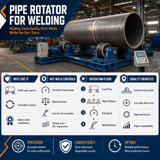
A turning roll is not itself certified to a welding code — it is the fixture that lets your welds meet one. What it has to deliver is rotation steady and controllable enough to hold a code-quality circumferential bead, so the root and cap stay in the flat position where penetration and fusion are most repeatable. That procedure is qualified under ASME BPVC Section IX; the shell or tank it serves is fabricated to its own code — API 650 for storage tanks, API 1104 for pipeline girth welds, or AWS D1.1 for structural work.
✔ What steady rotation buys you
- Even heat input around the joint — fewer porosity and undercut defects
- Continuous root-to-cap passes, no arc-strike restarts
- Repeatable travel speed for WPS compliance
- Single-operator high-quality welding on heavy work
⚠ What it will not fix
- A bad WPS or wrong consumables
- Fit-up gaps — square and tack first
- Drift on an out-of-round shell (manage it; see the fault map)
- Code certification — that is the procedure, not the fixture
Maintenance That Keeps Rolls Turning: Wheels, Bearings, Drive
A rotator is long-lasting equipment when the wear items are watched. Wheels are the first: steel rims carry the most weight and shrug off spatter, which is why hot, heavy pipes run on steel; polyurethane faces grip and protect a polished shell on lighter work but burn away under spatter. Replace wheels as a matched set so heights stay equal — a single new wheel reintroduces the roll-height delta that causes creep.
What maintenance practices ensure the longevity of a pipe welding rotator?
Build a short preventive checklist and hold to it. Bearings and the ground brush wear together on a rotating ground system, so inspect both; relubricate the drive on the maker’s schedule; and watch two predictive cues — a rising current draw on the drive and new vibration usually mean a bearing or alignment problem starting. Keep wheel faces clean of grease, confirm safety features like the emergency stop and guards work each shift, and lock out/tag out the drive (per OSHA 1910.147) before any roll service.
- ✔Wheel faces clean and matched; replace in sets
- ✔Bearings and ground brush inspected together; lubricate drive on schedule
- ✔Track drive current and vibration as early-failure signals
- ✔E-stop, guards and LOTO verified before service
Industry Outlook: Where Rotary Pipe Welding Is Heading
The operating story for the next few years is mechanization, and it is driven by people, not by a market-size headline. A skilled-welder shortage and tightening weld-data traceability (the procedure and qualification records in ASME BPVC Section IX) are pushing fabrication shops to get more finished weld out of each qualified welder — and steady rotation in front of a fixed, mechanized arc is the cheapest route there. Through 2025–2026 the visible moves are SAW-on-rolls for heavy seams, cobot and orbital heads riding turning rolls for repeatable girth welds, and arc-monitoring that logs travel speed and heat input straight off the drive. Market-growth figures for welding automation circulate widely (one often-quoted projection puts automated-welding CAGR around 8% to 2028) — treat that as directional background, not a forecast.
Buyers face a concrete action item: if you are specifying a pipe rotator this year, make it automation-ready now. Spec a true stepless drive, a proper rotary ground brush, and an anti-drift or self-aligning option even if today’s work is manual — those three are what a cobot or SAW head will need when you add it, and retrofitting them later costs more than ordering them in. Those same rolls that carry a hand-MIG job today become the motion base for welding automation tomorrow.
Frequently Asked Questions
What is a pipe welding rotator and how does it work?
View Answer
A pipe welding rotator is a wheel bed — a powered drive unit plus one or more idler units — that carries a pipe, tank or vessel and rotates it around its own horizontal axis at a steady, controllable speed. The welder holds the torch in one flat position while the part turns, producing a continuous circumferential weld with no cranes and no repositioning. Idler units ride behind the drive to support long pipe.
How do you set the rotation speed for pipe welding?
View Answer
Convert your WPS travel speed into roll RPM with the surface-speed rule: RPM = travel speed ÷ (π × pipe OD), in consistent units. A 24-inch pipe at 8 in/min needs 8 ÷ 75.4 = 0.106 rpm. Because RPM falls as diameter rises, larger shells need a stepless drive that resolves below 0.1 rpm — too fast under-penetrates the bead, too slow warps thin wall.
How do you ground the workpiece on a rotator for welding?
View Answer
Run the welding return current through a dedicated sliding contact — a copper-graphite brush or rotary ground shoe on the shell or drive shaft — not through the wheel bearings. Current that arcs across the rolling bearings pits the raceways and fails them early. Specify the return method and peak amperage with the order so the brush is rated for the job; a 500 amp SAW run and a 200-amp TIG run want different contacts.
Pipe rotator vs welding positioner, which do I need?
View Answer
Use a pipe rotator for long, heavy cylinders with circumferential seams; use a welding positioner for compact parts that need tilt and multi-angle access on a chuck. Long vessels go on rolls, small fixtured parts on a positioner. Our rotator vs welding positioner decider sizes it to your part.
Self-centering or automatic welding positioner units and bigger large positioners suit compact metalworking; conventional rotators and self-aligning rolls suit cylinders. Heavy fixtures rate capacity in tons, lighter benchtop units in lb capacity, and servo motors give the rotational precision and welding efficiency that automated, heavy-duty work needs.
Which welding processes work with a pipe rotator?
View Answer
SAW, mechanized MIG/MAG and orbital TIG all run on turning rolls. SAW gains the most because its flux only stays put in the flat position, which continuous rotation maintains. MIG with synergic control deposits a uniform bead at speed; TIG holds a tight pool for thin-wall and root passes.
How do I stop the pipe from drifting on the rolls?
View Answer
Most axial walk is a roll-height difference — level the two roll sets within a few millimetres and it usually stops. For out-of-round shells, use a self-aligning or anti-drift set and tack the shell round first. Slip is separate: degrease the wheels and check you are not over capacity.
How much maintenance does a pipe rotator need?
View Answer
Modest, but specific. Keep wheel faces clean and matched, inspect bearings and the ground brush together, lubricate the drive on schedule, and watch drive current and vibration as early-warning signs. Replace wheels as a set so roll heights stay equal, and lock out the drive before any service.
Drive motors on heavier sets run 2 x 2.2 kW at 110 to 575 V, and a drive wheel that loses even 2 mm of diameter shifts surface speed about 0.4% and reintroduces creep, so replace wheels as a matched set.
Sizing a pipe rotator for your heaviest workpiece?
Send ABOKE your heaviest part weight, diameter range and length for a capacity-matched recommendation — conventional, self-aligning or fit-up, 5–400 t.
Why We Wrote This Operating Guide
The RPM conversion, the 6-check setup routine and the grounding rule in this guide reflect the recurring operating questions ABOKE engineers answer on pipe-rotator RFQs across 40+ export markets — the things that decide whether a roll set welds clean or fights the operator, which a spec sheet never covers. Reviewed by the Aubrik (ABOKE) technical team.
References & Sources
- ASME BPVC Section IX — Welding, Brazing & Fusing Qualifications — ASME
- Submerged Arc Welding — overview — ScienceDirect Topics (Elsevier)
- US8342493B2 — Anti-drift turning roll system — USPTO via Google Patents
- GB2106810A — Compensating for longitudinal creep of rotating workpieces — UK IPO via Google Patents
- API Standards (API 650 / API 1104) — American Petroleum Institute
- AWS Welding Standards (D1.1, A3.0) — American Welding Society
- 29 CFR 1910.147 — The Control of Hazardous Energy (Lockout/Tagout) — OSHA