Get in Touch with Aubrik Company

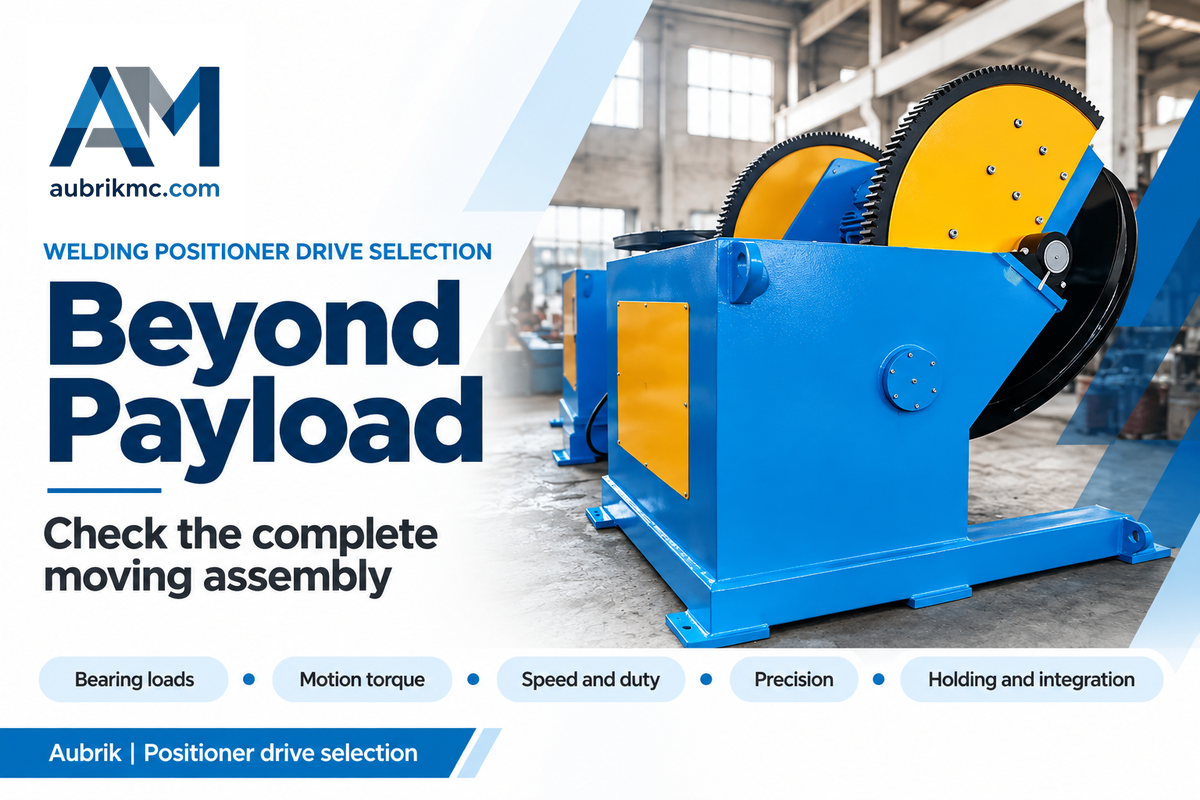
A slew drive for welding positioner involves a load supporting bearing and a geared rotary drive. Select it by assessing bearing loads, motion torque, welding speed, backlash and the machine’s holding arrangement. Payload alone can’t determine the right drive: fixture offset and axis orientation can alter the governing load case.
A compact rotary joint can simplify a positioner, but the purchase still requires a defined motor, brake and control package. Start with the complete moving assembly and weld path, then compare the drive ratings to requirements.
What a Slew Drive Does in a Welding Positioner
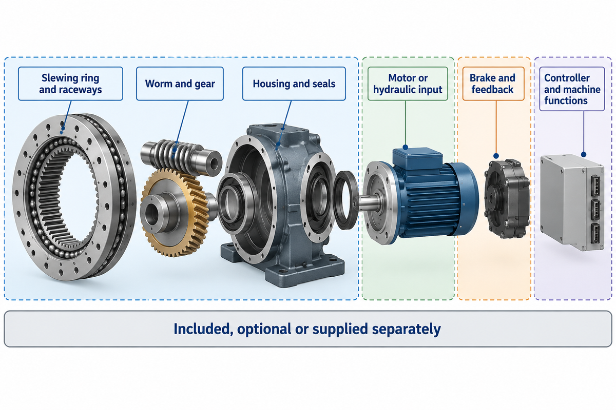
A slewing drive supports the moving assembly and transfers rotary motion through a geared bearing arrangement. A worm gear type usually integrates the slewing bearing, worm and housing. The motor provides the input power; the inclusion of the motor, brake and encoder must be stated in the quotation, as opposed to being inferred from the drive picture.
| Element | Function | Purchase-scope check |
|---|---|---|
| Slewing ring and raceways | Support the specified axial, radial and moment loads | Load curves and mounting conditions |
| Worm and gear | Transmit rotational torque through reduction | Ratio, duty and output torque |
| Housing and seals | Locate the assembly and protect internal parts | Mounting faces and environmental rating |
| Motor or hydraulic input | Provide the drive source | Included, optional or supplied separately |
| Brake and feedback | Provide the specified holding and position functions | Brake duty, encoder location and interfaces |
| Controller and machine functions | Coordinate speed, commands and stops | Integrator responsibility and acceptance scope |
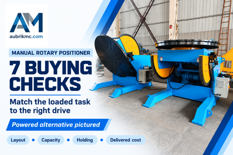
The high level of integration reduces the number of individual mechanical interfaces. It doesn’t render every slew bearing, gearbox and controller combination interchangeable. A bare slewing ring needs a separate drive mechanism; a modular drive package can still be without an electrical cabinet. For a complete machine compare the drive proposal to the fixture, worktable and controls supplied in Aubrik welding positioners.
5-Check Slew Drive Selector
The 5-Check Slew Drive Selector uses the buyer’s inputs to organize load support, motion torque, speed and duty, precision, and holding and integration.
Use the five headings in the request to the supplier. The selector is an information checklist; the manufacturer’s load assessment and the integrator’s machine design determine the accepted configuration.
Load and Torque: Size Each Axis Separately
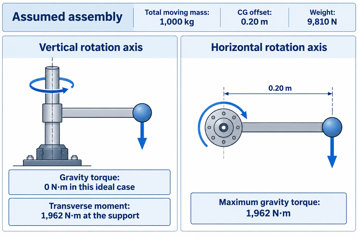
Size each positioner axis from its own load diagram. The combined workpiece and fixture determine weight and center of gravity; axis direction determines which components act axially or radially and whether gravity creates rotation torque. An overturning moment applied to the bearing is a different demand from torque transmitted through the gear.
What Loads Specify a Slew Drive for Welding Positioner?
Specify the complete moving mass, center of gravity, and radial and axial forces, along with the overturning moment, acceleration, and external process forces. Axial loads act along the bearing axis; radial loads act perpendicular to it. These definitions remain the same when the machine tilts. Record the most detrimental configuration as parts are added to the weldment.
Consider an assumed 800 kg workpiece on a 200 kg fixture, giving 1,000 kg total mass. Let the combined center of gravity sit 0.20 m from the rotation axis and use 9.81 m/s² for gravity. Weight is 1,000 × 9.81 = 9,810 N. On an ideal vertical axis, gravity produces no torque about that vertical axis, but the eccentric weight imposes a transverse overturning moment of 9,810 × 0.20 = 1,962 N·m on the support. Turn the rotation axis horizontal and the maximum gravitational rotation torque becomes 1,962 N·m, when the lever arm is perpendicular to gravity. The same mass now gives a different drive duty.
NASA Glenn’s torque relates moment to force and perpendicular lever arm. The assumed calculation above isolates gravity. Other factors, such as acceleration, friction, cables, and process forces, remain to be evaluated to complete the load case.
| Input or result | Vertical rotation axis | Horizontal rotation axis |
|---|---|---|
| Workpiece mass | 800 kg | 800 kg |
| Fixture mass | 200 kg | 200 kg |
| Total moving mass | 1,000 kg | 1,000 kg |
| CG offset from rotation axis | 0.20 m | 0.20 m |
| Weight | 9,810 N | 9,810 N |
| Gravity torque about rotation axis | 0 N·m in this ideal case | Maximum 1,962 N·m |
| Transverse moment from eccentric weight | 1,962 N·m at the support | Resolve from support and CG geometry |
| Acceleration torque | Calculate from rotational inertia and acceleration | Calculate from rotational inertia and acceleration |
| Friction and process loads | Add for the selected mechanism | Add for the selected mechanism |
Send the load cases together, rather than checking each catalog maximum independently. ISO 17956:2025 addresses an effective static safety-factor calculation for rolling bearings that considers effects including misalignment and internal load distribution. Its static scope does not replace fatigue or wear assessment. A rotary positioner selection guide helps define the surrounding machine; the drive supplier still needs the axis-specific loads.
Welding Speed, Duty Cycle and Motor Choice
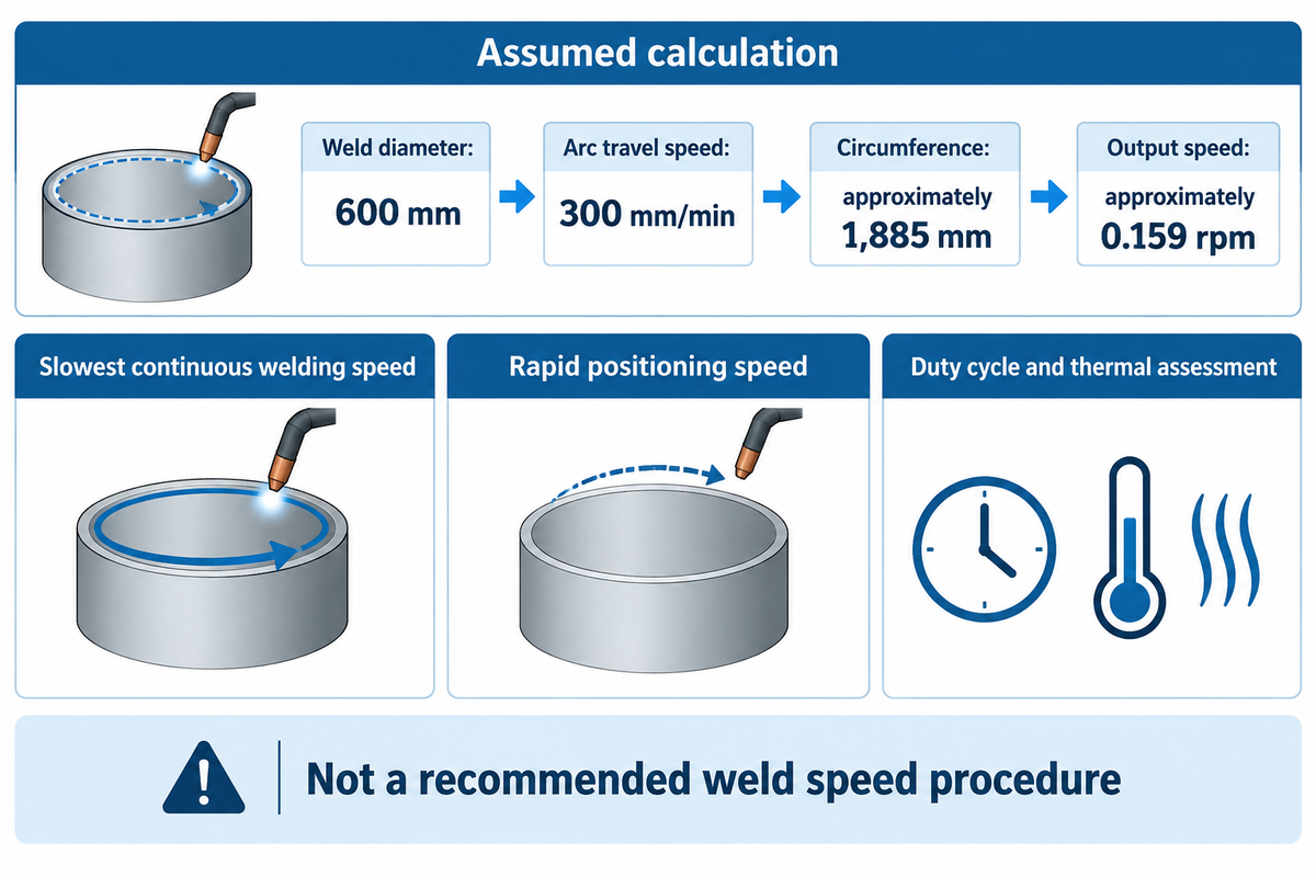
The required welding speed is the stable table output speed under the production load, not the motor maximum rpm. Calculate it from weld travel speed and joint circumference, then specify acceleration, repositioning speed and operating time. A drive that reaches the maximum speed can still regulate poorly during a slow circumferential weld.
“Wire feed speed is not the same as arc travel speed.”
For an assumed circular weld diameter of 600 mm and arc travel speed of 300 mm/min, circumference is π × 600 ≈ 1,885 mm. Required output speed is 300 ÷ 1,885 ≈ 0.159 rpm. These are input values for the calculation and not a recommended weld speed procedure. To determine the travel speed, consult the approved welder process. Ask the drive supplier to demonstrate speed regulation near 0.159 rpm under the stated load, rather than presenting only an unloaded high-speed demonstration. Keep in mind, if the fixture needs to reverse or accelerate between seams, include those movements in the duty cycle and thermal assessment.
QCB’s technical guidance usually limits its slew-drive load speed to 3 rpm, while identifying faster spur-gear options. This product-family limitation doesn’t reflect an industry-wide limitation. When selecting an electric motor, hydraulic motor or servo package, one must consider the selected ratio and the system efficiency. There can be significant differences in input and control requirements.
When addressing rotary welding positioners, state the slowest continuous welding speed separately from the rapid positioning speed. Terms such as stepless speed or precision motion do not establish a measurable tolerance. The acceptable variation should be specified at the weld seam, the load being positioned and the method of measurement.
Backlash and Stiffness at the Weld Seam
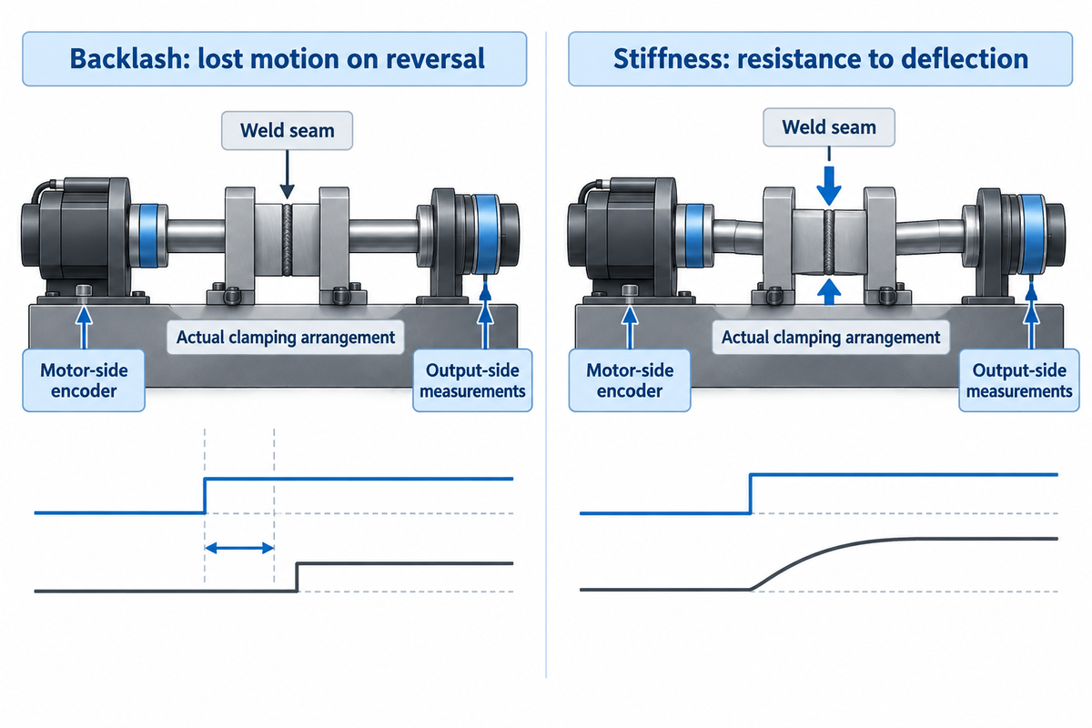
Backlash is lost motion when a drive reverses, and stiffness is resistance to deflection when a drive is loaded. The distinction also appears in research on compliance and backlash in robot machining; those results concern machining robots and provide no welding-positioner accuracy rating. Both can move the weld seam, but correcting one does not necessarily correct the other. Compare output-side measurements made at the same load and in the same direction, and distinguish positioning accuracy from repeatability before accepting a high-precision claim.
QCB’s measurement guidance distinguishes tracking angle from angle measured at the worm shaft. An input-shaft angle includes the reduction-ratio relationship and cannot be copied directly into an output-backlash specification. Determine where an indicator or encoder is placed, what’s held fixed and what load is applied during a test.
Consider a fixture that allows welds to occur continuously in one direction, and reverses for a second seam. A successful first seam indicates that the loaded drive can rotate steadily in that direction. It doesn’t determine where the joint will settle upon reversal. The gear clearance and the fixture’s elastic deformation can be examined separately by a designer. The production team can then define an acceptance check at the workpiece radius, using the actual clamping arrangement. Improving the encoder resolution won’t remove structural errors if the commanded position is reported by a motor-side encoder while the fixture deflects. The purchasing specification should state which output measurement must pass.
Ring support, housing attachment, fixture stiffness, and gearing should be reviewed at the same level of precision. A nominally high rotational torque rating doesn’t describe seam location accuracy. For larger workpieces, consider the case where the loading direction changes as the assembly rotates.
Self-Locking, Braking and Alternative Drives
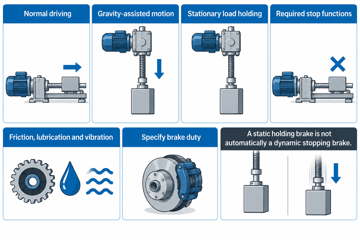
For a self-locking worm drive, back-driving may be prevented under defined conditions, but that description does not specify the machine stopping or holding performance. Friction, lubrication and vibration affect behavior. Evaluate normal driving, gravity-assisted motion, stationary load holding and the required stop functions as separate operating cases.
In worm-gear Self-Locking, the effects of lead angle and friction are reported and the case for using a brake is presented over relying on self-locking. Brakes must be specified for the intended duty. A static holding brake cannot automatically be treated as a repeatedly applied dynamic stopping brake.
QCB describes stick-slip when inertia or gravitational loads drive the load ahead of a low-efficiency worm mechanism. Its guidance specifically calls for twin-scroll drives on electrically driven horizontal rotation axes. That’s their configuration rule. Ask the selected manufacturer how its proposed arrangement handles an assisting load, rather than applying that rule to every custom slew design.
Integrated worm gear slew drive
- Combines bearing support and geared rotary motion.
- Requires product-specific checks for backdriving and low-speed duty.
- Needs a defined brake and control scope.
Separate geared-bearing drive
- Allows a separately selected gear reducer and input package.
- Requires coordinated bearing, pinion and mounting design.
- Needs a defined brake and control scope.
A planetary gear stage can also provide reduction in a drive package, and it won’t replace the function of the slewing bearing in load support. Spur-gear and worm-drive solutions should be compared under the same speed, load-holding, and duty requirements rather than ranked by a general statement.
Using Aubrik SE-Series Catalog Ratings
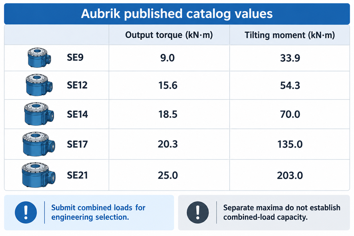
The Aubrik SE-Series has five models with separate tilting Moment, axial Load, radial Load and Output-torque. Use these values as a screen, and then submit combined loads for engineering selection. Maximum values don’t ensure that a drive can meet all combined loads during the required welding duty.
| Model | Tilting moment (kN·m) | Axial load (kN) | Radial load (kN) | Output torque (kN·m) | Ratio | Mass (kg) |
|---|---|---|---|---|---|---|
| SE9 | 33.9 | 338 | 159 | 9.0 | 61:1 | 48 |
| SE12 | 54.3 | 475 | 190 | 15.6 | 78:1 | 60 |
| SE14 | 70.0 | 555 | 220 | 18.5 | 85:1 | 65 |
| SE17 | 135.0 | 900 | 350 | 20.3 | 102:1 | 98 |
| SE21 | 203.0 | 1,598 | 640 | 25.0 | 125:1 | 120 |
The SE-series slew drive sizer is the starting point of the published range. Output torque and tilting moment have different functions; the 1,962 N·m example doesn’t identify the model without the remaining bearing loads, duty and installation requirements.
For heavy-duty welding positioners, provide the complete fixture drawing and all working orientations. A large offset and Heavy loads can make the bearing assessment critical, prior to the motor reaching its torque limit.
Cost and Slew Drive Manufacturer Choices
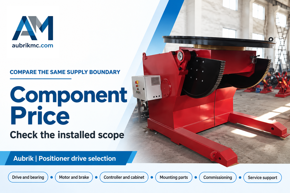
Compare slew-drive quotations by matching the complete supply scope. For a complete machine, compare the fixture and control requirements with its complete positioner supply scope. Component price doesn’t include costs that may be located in other parts of a motor, brake, controller or mounting package. Some of the manufacturer pages reviewed offer configured products or quotation requests, but don’t supply a price for an installed package in a general sense for comparison.
| Quoted item | Evidence to request | Owner of the decision |
|---|---|---|
| Drive and slewing bearing | Exact model, ratio and load assessment | Mechanical design |
| Motor and adapter | Motor specification, coupling and interface drawing | Mechanical and controls |
| Brake | Holding or stopping duty and integration scope | Machine integrator |
| Encoder | Type, location and controller compatibility | Controls |
| Controller and cabinet | Included functions and electrical interfaces | Controls and production |
| Mounting parts | Flanges, supports and fastener supply boundary | Mechanical design |
| Weld-current return | Rated return-path arrangement for the process | Welding engineering |
| Commissioning | Loaded speed, reversal and machine-function acceptance | Production and integrator |
| Service support | Lubricant specification, spares and documentation | Maintenance and procurement |
Suppose procurement gets a quotation for a sealed drive with an input flange, and a second quotation for a drive, motor and brake. When comparing total costs, assigning the missing motor and brake in the first quotation a price of zero would understate the installed cost. A better approach is to have both vendors complete the worksheet to indicate whether an item is included, optional or supplied by the integrator. Only after the machine builder has identified the cabinet, mounting and commissioning work, can Finance compare the scope of work. Maintenance should also review the documentation and spares list before the order. Lower component prices can be useful, but only after the supplier’s scope and associated costs have been identified and a corresponding quote is available.
A slew drive manufacturer provides the rotary subassembly; a positioner integrator coordinates fixturing and motion control and machine functions. IMO identifies motors, brakes, planetary stages and encoders as configuration options; Slewmaster describes welding-positioner drive applications. These illustrate varying supply boundaries, and aren’t interchangeable approved packages. Compare custom solutions against the same drawing and acceptance criteria.
Maintenance and Fault Diagnosis
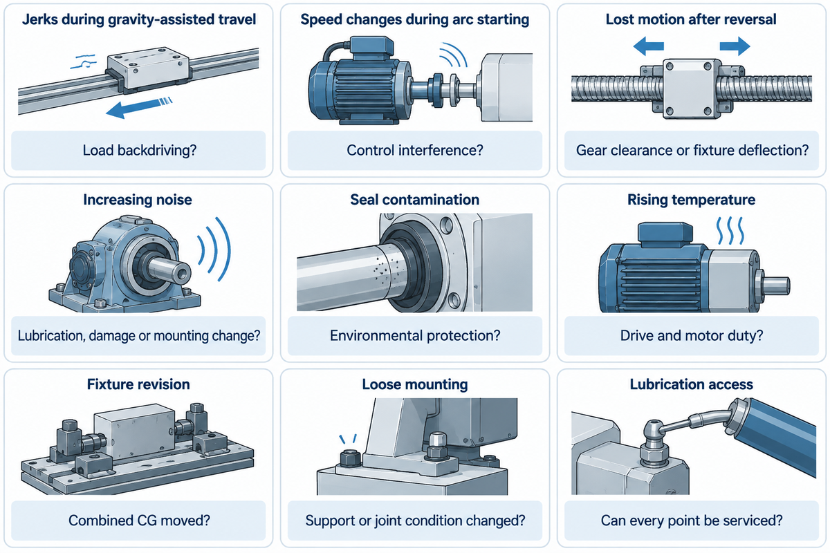
The selected drive lubrication and inspection instructions are the starting point for planned maintenance. Raceway, worm gearing and worm-support bearings can have different lubrication points and quantities. Unusual noise, excessive heat, or irregular movement can indicate a fault requiring diagnosis. Adding grease alone cannot identify whether the fault is mechanical or electrical. Irregular movement can also be caused by an unbalanced load.
QCB separates lubrication recommendations based on environment: dry and clean conditions allow 1,000 hours or 12 months, while aggressive conditions allow 50 hours or 2 months. These intervals are specified for QCB’s products and conditions; intervals in its WGR family have different recommendations. Don’t interchange these limits with Aubrik assemblies. Welding shops should give the supplier their dust, spatter and cleaning conditions when requesting the service schedule.
| Observed condition | Question to resolve | Required evidence |
|---|---|---|
| Jerks during gravity-assisted travel | Is the load backdriving the mechanism? | Load direction and selected drive’s guidance |
| Speed changes only during arc starting | Is interference affecting the control system? | Integrator-led process-on acceptance results |
| Lost motion after reversal | Gear clearance or fixture deflection? | Separate output and structural measurements |
| Increasing noise | Lubrication, damage or mounting change? | Inspection against the maintenance manual |
| Seal contamination | Does protection match the environment? | Seal condition and cleaning history |
| Rising temperature | Does duty match the drive and motor ratings? | Loaded duty record and supplier limits |
| Changed load after fixture revision | Has combined CG moved? | Updated mass and load-case drawing |
| Loose mounting connection | Has support or joint condition changed? | Inspection to the specified mounting procedure |
| Uneven lubrication access | Can every required point be serviced? | Installation drawing and lubricant instructions |
An operator named dkmc reported in a 2024 Practical Machinist discussion that a DIY DC positioner worked with MIG, but high-frequency TIG caused it to start at full speed. Related controller questions by the same operator were posted in 2025. These posts identify a useful integration test, not a verified repair or a failure rate for modern welding systems. Have the integrator evaluate the assembled controls with the intended welding process.
Do
- Record symptoms with load direction and process state.
- Use the selected drive’s lubricant and service instructions.
- Reassess the load after changing the fixture.
Don’t
- Copy another manufacturer’s lubrication interval.
- Treat a controller change as proof of a mechanical repair.
- Assume self-locking makes maintenance access safe.
Integration and Commissioning Requirements
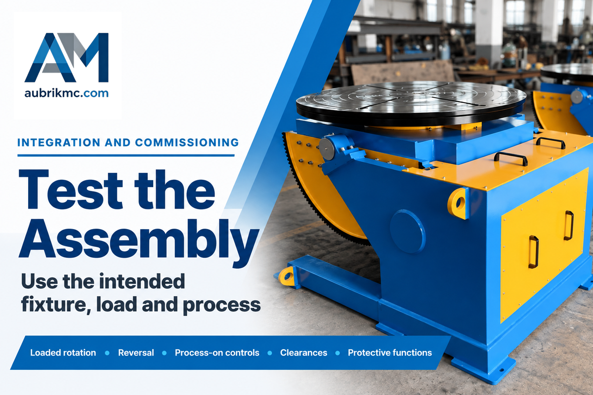
The integrator must coordinate mounting stiffness, clearances, welding current return, controls and protective functions before releasing a positioner for production. An assembled drive’s rating covers part of this. Acceptance should use the intended fixture, representative load and welding process, including low-speed motion and the required stop behavior.
Is there an optimal orientation to mount the slew drive?
The mounting orientation must match the manufacturer’s approved load cases and lubrication arrangements. A vertical axis and a horizontal axis impose different gravity and bearing-load cases. An assembled positioner changes the load path as the tilt axis moves. Verify accessible lubrication points, mounting-face support and clearances over the full operating range.
Honhart’s positioner discussion warns that welding current passing through bearings can adversely affect them. It’s recommended to provide a suitably rated arrangement to return welding current to the process rather than depending on incidental contact through the drive. A range of industries uses rotary welding, but construction machinery fixtures and small tube workpieces require different interfaces and clearances.
ISO 12100:2010 provides a machinery risk-assessment and risk-reduction framework. IEC 60204-1:2016+AMD1:2021 addresses electrical equipment of machines. Referencing these documents defines relevant design work; it does not establish a product certification.
OSHA 1910.212 (US) relates to guarding including rotating parts and nip points. OSHA 1910.147 (US) relates to specified servicing and maintenance of machines where unexpected startup or release of stored energy can be a hazard. A control pushbutton isn’t an energy-isolating device. For a machine-specific assessment, it’s necessary to differentiate between normal production and servicing/maintenance conditions.
It’s recommended to ask the integrator for a recorded acceptance of the loaded rotation, reversal, process-on control behavior, clearances, and the protective functions required. It’s only worthwhile requesting Long life performance and welding quality and efficiency once the supplier has agreed the assembly will be checked in a particular way.
Frequently Asked Questions
What is a slew drive?
A slew drive combines a load-supporting slewing bearing with a geared drive mechanism and housing.
Component and supply details
The assembly supports the specified loads while transmitting rotary motion through its gearing. A worm gear slew arrangement is one common configuration. The motor, encoder and brake depend on the supplied package. A geared bearing alone remains a component and doesn’t produce powered rotation by itself. Check the drawing and quotation to distinguish the mechanical assembly from the complete controlled axis.
Why do welding positioners use slew drives?
Slew drives offer a compact way to support and rotate a welding fixture and workpiece.
Where the arrangement fits
The bearing and gearing share an assembly, which can reduce separate mechanical interfaces in a rotary drive. Suitability still follows the axis orientation, complete moving mass, operating speed and duty. A highly integrated mechanism needs compatible controls and fixturing. Its modular design can help package the axis, but the machine builder must establish the required holding arrangement and loaded performance.
What is the efficiency of a slew drive?
Efficiency is product-specific; QCB describes many of its single-start worm drives as about 40 percent efficient.
How to use an efficiency figure
That gearing figure belongs to the products and conditions described by QCB. It isn’t the efficiency of every slewing drive, electric motor or complete welding positioner. A single stage of gearing also differs from a package containing additional reduction stages. Obtain the selected configuration’s performance information for motor and thermal calculations. Efficiency alone can’t establish a safe braking function.
What is the maximum speed of a slew drive?
Use the selected drive’s output-speed rating and duty limit.
Input and output speed
QCB usually restricts its slew-drive load speed to 3 rpm and identifies faster spur-gear options. That’s a product-specific statement. The motor’s input speed isn’t the worktable’s output speed.
Do I need to use all the internal grease to grease the bearing raceway?
Use the quantity specified for each lubrication point in the selected drive’s instructions.
Raceway and gear lubrication
QCB distinguishes the raceway, worm gear and worm-support bearings and lists separate grease quantities. Applying one quantity to every port ignores those differences. Obtain the specified lubricant, quantity, interval and distribution procedure before servicing. Internal gear or raceway arrangements should be identified from the assembly drawing, rather than assumed from another model. Record which points were serviced and any contamination found so maintenance can track changes against the same configuration.
Is a slew drive the same as a worm gearbox?
A worm gearbox provides reduction; an assembled slew drive also incorporates the load-supporting bearing arrangement.
Separate mechanisms
A separate gearbox can drive a geared bearing. Its interfaces, bearing loads, mounting and holding functions still need coordinated design.
Can an existing welding positioner be retrofitted with another drive?
A retrofit requires the replacement drive to match the revised machine’s loads, interfaces and functions.
Retrofit information to collect
Compare mounting dimensions, motor interfaces, ratios, output-speed range and the holding arrangement. Include the fixture and workpiece geometry rather than copying the old payload label. Request a combined-load assessment for the proposed configuration. The integrator then needs to check stiffness, clearances, cable routing, weld-current return and stop behavior with the replacement installed. Keep the revised drawings, settings and acceptance record with the maintenance documentation so future changes are assessed against the correct machine.
References & Sources
- Torque, NASA Glenn Research Center.
- ISO 17956:2025, rolling bearings: effective static safety factor, International Organization for Standardization, public scope.
- Putting the spin on benchtop positioners for tube and pipe welding, Keith Honhart, The Fabricator, May 2003.
- Hybrid compliance compensation for path accuracy enhancement in robot machining, Production Engineering; adjacent robotics research.
- Self-locking in worm gears: how does it work and where is it useful?, Motion Control Tips.
- ISO 12100:2010, machinery risk assessment and risk reduction, International Organization for Standardization, public scope.
- IEC 60204-1:2016+AMD1:2021, electrical equipment of machines, International Electrotechnical Commission, public product description.
- 29 CFR 1910.212, general requirements for all machines, US Occupational Safety and Health Administration.
- 29 CFR 1910.147, control of hazardous energy, US Occupational Safety and Health Administration.
Related Reading
- Heavy-duty welding positioner selection
- How to use a welding positioner
- Pipe rotators for welding
- Welding positioners and turntables
Discuss Your Positioner Drive Requirements
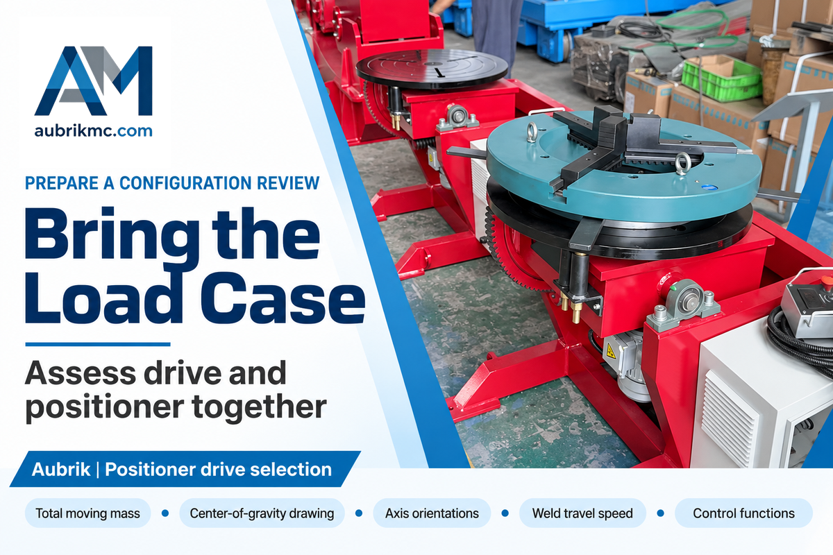
Send Aubrik the total moving mass, center-of-gravity drawing, axis orientations, weld travel speed and required control functions. Include the intended fixture and welding process so the drive and complete positioner can be assessed together.