Get in Touch with Aubrik Company

Column and Boom Welding Manipulator Engineering Guide: Stroke Sizing, Cantilever Deflection Control, and Turning Roll Integration

Engineering Selection & FAT Reference | Wuxi ABK Machinery (Aubrik) Welding Automation Engineering Team | Reviewed October 2026
Quick Engineering Answer (TL;DR)
A column and boom manipulator is a multi-axis structural positioning tower. It carries a welding head along vertical column lift (
1,000–15,000 mm
) and horizontal boom reach (
1,000–15,000 mm
). These automated systems regulate horizontal travel across
50–1,200 mm/min
, or
300–3,000 mm/min
on high-speed rack-and-pinion models. Full-load boom-tip droop stays below
0.5 mm per meter
of reach (
1.5–3.0 mm
maximum static sag).
- Stroke Sizing Formula: Vertical lift must clear the turning roll bed height plus maximum shell outer diameter plus torch stack height (
Hlift ≥ Dmax + Hroller + Htorch - Hmin
). - Boom-Tip Payload Budget: Bare welding heads weigh
35–55 kg.
Full packages of submerged arc with heated flux hoppers, vacuum recovery, wire spools, and cross-slides weigh
180–750 kg
. - 12 O’Clock Circumferential Offset: External vessel girth welds require a
15–45 mm
uphill torch offset from top dead center to keep molten slag from flooding the arc. - Vertical Anti-Fall Protection: Prevents carriage drops on heavy masts using dual ACME safety nuts with wear sensors or counterweighted chains with ratchet locks.
Ordering a nominal 4,000 × 4,000 mm welding boom by matching catalog stroke to tank diameter is a costly mistake. Once a pressure vessel sits on self-aligning turning rolls, the roller bed adds 550–850 mm to the shell elevation.
550–850 mm
assemble the legs to the desired height. Meanwhile, the submerged arc torch assembly, motorized cross-slides, and flux nozzle hang 300–450 mm below the adjustable boom. Without both vertical offsets accounted for, the welding column cannot clear top dead center on your largest shell. Heavy welding equipment and CNC systems demand exact geometric clearance checks before fabrication begins.
Horizontal reach and cantilever stiffness fail in the same way when buyers only check bare torch weight. A catalog table may list a flat 454 kg (1,000 lbs) static load across multiple boom and column sizes. However, adding a heated flux hopper, vacuum separator, dual wire reels, and operator seat pushes boom-tip weight to 450–750 kg.
That overturning moment causes elastic droop during heavy welding work. This leads to the moment where the system becomes unstable.
Even 2–3 mm
of vertical sag causes contact-tip-to-work distance (CTWD) to increase enough to ruin quality welding along a
9 m
seam. Because the boom allows long internal reach across demanding welding applications, every specific welding procedure requires verified deflection limits. This guide will provide stroke equations, payload budgets, and Factory Acceptance Testing (FAT) to help you define your welding tools and welding equipment.
How a Column and Boom Welding Manipulator Moves the Weld Head Across Three Axes
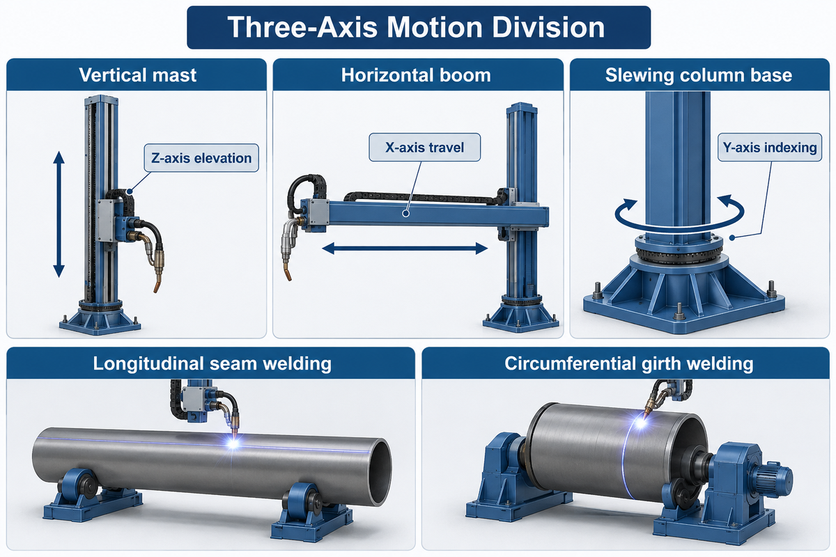
An industrial column and boom manipulator moves the welding head across three axes at variable-frequency drive (VFD) speeds of
50–1,200 mm/min
. High-speed rack-and-pinion carriages reach
300–3,000 mm/min
, as published in Wuxi ABK
AM-CB
series and AMET Inc. specifications. A vertical mast controls the Z-axis elevation, and a horizontal boom provides X-axis travel.
A slewing column base or motorized rail car allows for Y-axis indexing with this heavy welding machine. It uses a vertical mast with a rigid machine-tool gantry structure. Welding manipulators are designed to maintain consistent weld quality across multi-pass joints, including MIG, TIG, and submerged arc processes. In vessel shops the division of labor between the column welding tower and the roller bed is strict. As documented by the American Welding Society (AWS) Welding Digest (October 2026) and the AWS Practical Reference Guide to Positioning, the manipulator moves the torch along the weld path. A welding positioner or turning roll set, on the other hand, rotates the workpiece into the flat downhand (1G/PA) orientation.
“The arm (Manipulator) is made up of many joints that allow movement across multiple axes. Positioner (Fixture): Holds and rotates the workpiece to position the weld joint in the most advantageous position (flat, horizontal, etc.). Welding head manipulators hold and move the welding head and welding torch (as the weld is made).”
During longitudinal seam welding on a pipe or tank shell, the turning rolls lock the cylinder stationary. The horizontal boom or MIG column then drives the welding head along the X-axis at a regulated cruise speed. As reported in The Fabricator’s technical review of manipulator safety and speed controls, industrial boom drives operate across two speed regimes. A fast positioning mode runs near
10 FPM
(
3,048 mm/min
). Fast positioning between joints reduces downtime, while a welding mode regulates travel
between 6–30 IPM
(
152–762 mm/min
) to deliver a consistent weld with deep penetration.
During circumferential girth welding, the roles reverse. The horizontal boom locks stationary while the turning rolls rotate the cylindrical shell beneath the torch. The Programmable Logic Controller (PLC) synchronizes rotational speed
n
(in RPM) with linear speed
v
(in
mm/min
) and shell diameter
D
(in
mm
). It uses the closed-loop equation
n = v / (π · D)
for fully automated circumferential passes. Operators offset the torch
15–45 mm
At 12 o’clock top dead center on external welds. Internal girth welds use a 15–45 mm uphill offset ahead of 6 o’clock bottom dead center. Closed-loop encoder feedback on anti-creep turning rolls restricts axial vessel spiral drift within ±1.5 mm per revolution.
±1.5 mm
per revolution.
Check your shop crane hook height and aisle spacing before selecting a frame class. Total vertical mast height equals vertical stroke plus
1,100–1,600 mm
They cover top pulley assemblies. You must also confirm the rear boom tail-swing radius.
| Model / Duty Class | Vertical Lift Stroke (Z) | Horizontal Boom Reach (X) | Rated Boom-Tip Load | Horizontal Travel Speed | Primary Industrial Application |
|---|---|---|---|---|---|
| Light Portable (e.g., LJ MNP-600) |
1,220 mm(4 ft) |
1,520 mm(5 ft) |
272 kg(600 lbs) |
100–1,500 mm/min
|
Small pipe spools, shop sub-assemblies |
| Compact Standard (AM-CB-20 / Key Plant SD) |
2,000 mm
|
2,000 mm
|
150–300 kg
|
50–1,200 mm/min
|
Light tanks, GTAW/MIG longitudinal seams |
| Medium Duty (Aubrik AM-CB-30 / LJ MN30-100) |
3,000 mm(10 ft) |
3,000 mm(10 ft) |
300–500 kg
|
50–1,200 mm/min
|
Single-wire SAW pressure vessels, boilers |
| Modular ACME Series (AMET Systems) |
1,000–4,000 mm
|
1,000–4,000 mm
|
150–600 kg(+ 50 kgcounterweight) |
300–3,000 mm/min
|
Precision SAW, PAW, GTAW, bore cladding |
| Heavy Vessel (Aubrik AM-CB-40) |
4,000 mm
|
4,000 mm
|
500–800 kg
|
120–3,000 mm/min
|
3.2 m OD heat exchangers, chemical shells |
| Heavy Industrial (Aubrik AM-CB-50 / LJ MN16-100) |
4,880–5,000 mm
|
4,880–5,000 mm
|
454–1,000 kg
|
120–3,000 mm/min
|
Petrochemical drums, dual-head SAW |
| Extra Heavy Duty (Aubrik AM-CB-60 / PEMA HD) |
6,000 mm
|
6,000 mm
|
800–2,000 kg
|
120–3,000 mm/min
|
Tandem SAW with operator seat, wind cans |
| Ultra Tower (Pemamek PEMA EHD) |
8,000–10,000 mm
|
8,000–10,000 mm
|
1,200–2,000 kg
|
100–2,500 mm/min
|
Offshore wind monopiles, nuclear vessels |
| Mega Shipyard Tower (Key Plant EHD) |
12,000–15,000 mm
|
12,000–15,000 mm
|
1,500–2,500 kg
|
100–2,000 mm/min
|
LNG storage spheres, shipyard hull blocks |
Sizing Vertical Stroke, Horizontal Boom Reach, and Minimum Internal Pipe Clearance
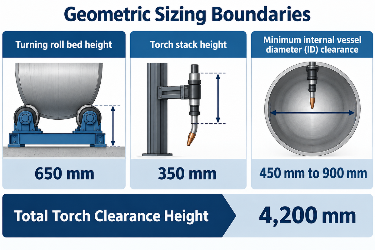
Minimum internal vessel diameter (ID) clearance ranges from
450 mm to 900 mm
These parameters depend on boom box-beam height and the position of the torch. These are based on Key Plant, LJ Welding, and AM-CB series column and boom welding manipulator specifications. Appropriate clearance allows for longitudinal and girth pipe welding without boom interference.
Sizing a boom welding manipulator system or cab manipulator requires checking three geometric boundaries: maximum external vertical height, effective internal horizontal reach, and minimum internal pipe clearance. Buyers frequently confuse vertical travel stroke (Sv) with maximum height under the boom (Hmax). Maximum height under the boom equals minimum saddle elevation (Hmin, typically 650–950 mm above the floor) plus vertical stroke (Hmax = Hmin + Sv). Similarly, usable internal pipe weld length is always
350–600 mm
shorter than nominal horizontal stroke (
Sh
1. The Column Base: The front Torch Slide Overhang and rear Cable Drag Loop reduce the available travel margin.
How Do You Calculate Required Vertical Column Lift When Pairing a Manipulator With Turning Rolls?
Calculate required vertical boom height by summing three vertical dimensions: turning roll bed height (Hroller), maximum vessel outer diameter (Dmax), and torch downward stack clearance (Htorch).
Hmin
) to find the minimum vertical lift stroke (
Sv
):
H_max_required = H_roller + D_max + H_torch / S_v_required ≥ H_roller + D_max + H_torch – H_min
Worked Sizing Example (
3,200 mm
(OD Pressure Vessel Shell): What shop welds pressure vessel shells with outer diameter?
Dmax = 3,200 mm
and shell length
Lshell = 3,500 mm
. The vessel sits on a
60-ton
self-aligning turning roll bed. First, assume the roller cradle elevates the shell bottom to the roller bearing surface.
Hroller = 650 mm
above the floor. 2) Imagine a tandem submerged arc welding (SAW) head, cross-slides, and nozzle projects.
Htorch = 350 mm
Below the boom. Third, suppose the minimum height of the bottom-stop of the manipulator carriage is
Hmin = 700 mm
.
- Step 1 (Total Torch Clearance Height):
Hmax_required = 650 mm + 3,200 mm + 350 mm = 4,200 mm
minimum underside boom elevation. - Step 2 (Net Vertical Travel Stroke):
Sv ≥ 4,200 mm - 700 mm = 3,500 mm
minimum vertical stroke. - Step 3 (Horizontal Boom Reach): Adding
500 mm
column base standoff to the
3,500 mm
shell length requires
Sh = 3,500 mm + 500 mm = 4,000 mm
horizontal stroke. - Step 4 (Model Selection & Structural Scope): A nominal
3,000 × 3,000 mm
unit falls
500 mm
short on vertical lift. Select a4,000 × 4,000 mmclass unit (such as theAM-CB-40), and pair this stroke calculation with Table 3 bending moment limits and Section 8 anchor bolt checks.
Check the boom cross-section against Table 2 before ordering a heavy box beam for internal pipe welding operations. A standard
500 × 400 mm
box beam cannot enter a
600 mm
ID pipe. Instead, specify a bolt-on narrow reach lance (120 × 120 mm profile) with an external flux hopper and camera monitor.
| Boom / Lance Configuration | Structural Beam Profile (H × W) | Mounted Head Stack Height | Minimum Internal Pipe ID | Max Cantilever Reach | Typical Welding Process |
|---|---|---|---|---|---|
| Micro Bore Cladding Lance |
90 × 90 mmmachined alloy bar |
110 mmlow-profile torch |
280–350 mmID |
1,800 mm
|
Hot-wire GTAW / Inconel bore overlay |
| Narrow Pipe Reach Lance |
130 × 130 mmtubular lance |
160 mmcompact GMAW/SAW |
400–450 mmID |
2,500 mm
|
Automatic pipe welding (MIG / mini-SAW) |
| Compact Box Boom (Small Manipulators) |
220 × 180 mmbox section |
220 mmcompact head |
550–650 mmID |
2,500 mm
|
Single-wire GMAW/GTAW/SAW |
| Standard Duty Boom (3×3 m Class) |
320 × 260 mmbox beam |
280 mmSAW + remote hopper |
750–850 mmID |
3,000 mm
|
Single-wire SAW with tactile probe |
| Medium Duty Boom (4×4 m Class) |
420 × 340 mmstiffened box |
340 mmSAW + local hopper |
900–1,050 mmID |
4,000 mm
|
Single-wire SAW + vacuum flux recovery |
| Heavy Duty Boom (5×5 m Class) |
520 × 420 mmribbed beam |
400 mmheavy SAW package |
1,150–1,300 mmID |
5,000 mm
|
High-deposition DC/AC single or twin SAW |
| Extra-Heavy Boom (6×6 m Class) |
650 × 500 mmbox girder |
480 mmtandem SAW + slides |
1,400–1,600 mmID |
6,000 mm
|
Tandem twin-arc SAW + laser tracker |
| Boom With Operator Seat / Cab |
650 × 550 mm+ cab cage |
1,350 mmseated clearance |
2,400–2,800 mmID |
6,000–8,000 mm
|
Wind tower & penstock internal seams |
| Ultra Wind/Nuclear Girder (10×10 m) |
850 × 650 mmtwin-web beam |
600 mmmulti-wire tandem |
3,000–4,500+ mmID |
10,000–15,000 mm
|
Offshore monopiles, narrow-gap SAW |
Controlling Boom-Tip Deflection, Cantilever Droop, and Travel Speed Ripple at Full Reach
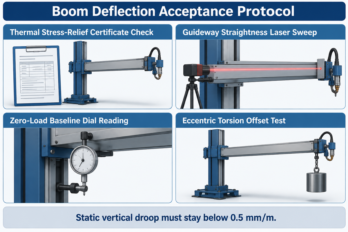
Static boom-tip vertical droop at 100% horizontal extension under rated head load must not exceed
1.5–3.0 mm
. That equals less than 0.5 mm per meter of boom reach, per Aboke’s industrial manipulator engineering benchmarks. When a welding boom sags by 2–3 mm along a 9 m longitudinal tank seam, the contact-tip-to-work distance (CTWD) elongates. Arc voltage increases, and weld seam suffers from porosity or undercut.
Industrial accuracy benchmarks published by WeldMC specify tight motion tolerances for precision column boom welding systems. Uniaxial positioning accuracy stays within
±0.05 to ±0.5 mm
, and repeat positioning accuracy stays within
±0.1 to ±1.0 mm
. In addition, US Navy Crane Center Instruction NAVCRANECENINST 11450.2A warns that heavy cantilever loads on column-and-boom structures cause support drift. Prior to welding, rotational slewing inertia torque must be locked and preloaded mechanically.
Does a Longer Welding Boom Always Carry Less Weight at Full Extension?
Yes, a longer boom experiences exponentially greater bending deflection unless the manufacturer steps up the box-beam section modulus. Catalog tables often print the same nominal load—such as 454 kg (1,000 lbs) on both a 3.0 × 3.0 m unit and a 4.9 × 4.9 m unit.
δ
follows the cubic beam equation
δ = (F · L3) / (3 · E · I)
. Doubling horizontal extension
L
from
2.5 m
to
5.0 m
under the same tip force
F
multiplies elastic droop eightfold unless the moment of inertia
I
increases proportionally.
Side-mounted welding heads also create eccentric torsional twist (
θtwist
As described in Chinese utility model patent CN211387216U, heavy-duty manipulators counteract cantilever droop by means of welding internal diagonal stiffening ribs in a stress-relieved box girder. Manufacturers, however, machine cold-drawn square guide rails, or mount linear ball guideways, as used in Pemamek PEMA HD/EHD units. Further, they preload eccentric cam follower rollers to eliminate saddle backlash. Use the Cantilever Moment-to-Droop Envelope in Table 3 to set your purchase order tolerances.
| Horizontal Boom Reach (L) | Nominal Rated Payload | Max Safe Operating Load (80% Rule) | Tip Bending Moment (M = F · L) | Precision FAT Max Droop (<0.5 mm/m) | VFD Travel Speed Ripple |
|---|---|---|---|---|---|
2.0 m(6.5 ft) |
200 kg
|
160 kg
|
3.92 kN·m
|
≤1.0 mm
|
±1.0%
|
3.0 m(10 ft) |
350 kg
|
280 kg
|
10.30 kN·m
|
≤1.5 mm
|
±1.0%
|
4.0 m(13.1 ft) |
500 kg
|
400 kg
|
19.62 kN·m
|
≤2.0 mm
|
±1.0%
|
5.0 m(16.4 ft) |
650 kg
|
520 kg
|
31.88 kN·m
|
≤2.5 mm
|
±1.2%
|
6.0 m(19.7 ft) |
1,000 kg
|
800 kg
|
58.86 kN·m
|
≤3.0 mm
|
±1.2%
|
7.0 m(23.0 ft) |
1,200 kg
|
960 kg
|
82.40 kN·m
|
≤3.5 mm
|
±1.5%
|
8.0 m(26.2 ft) |
1,500 kg
|
1,200 kg
|
117.72 kN·m
|
≤4.0 mm
|
±1.5%
|
9.0 m(29.5 ft) |
1,800 kg
|
1,440 kg
|
158.92 kN·m
|
≤4.5 mm
|
±1.5%
|
10.0 m(32.8 ft) |
2,000 kg
|
1,600 kg
|
196.20 kN·m
|
≤5.0 mm
|
±1.8%
|
Prior to approving shipment from the manufacturer’s plant, execute the 8-Point Boom Deflection Acceptance Protocol to ensure welding head stability and eliminate rework:
- Thermal Stress-Relief Certificate Check: Inspect furnace annealing charts (
580–620 °C
Soak the welded column and boom box girders before guideway milling. - Guideway Straightness Laser Sweep: Machined cold-drawn rail or linear guideway straightness must stay within
≤0.15 mm
per
1,000 mm
length. - Zero-Load Baseline Dial Reading: Retract the boom to
0%stroke and zero a magnetic dial indicator at the torch mount. Then run the boom out to
100%
stroke empty. - 100% Static Dead-Weight Test: Suspend calibrated test weights equal to
1.0x
rated payload at the boom tip at
100%
extension. Static vertical droop must stay below
0.5 mm/m
. - 125% Overload Proof Test: Apply
1.25xrated load at full extension for30 minutes. - Eccentric Torsion Offset Test: Offset the test weight
250 mm
laterally from the boom centerline to represent a side mounted SAW head. Angular twist should remain constant.
0.08°
. - Low-Speed VFD Stick-Slip Test: Drive the loaded boom at minimum welding speed (
50–100 mm/min
). Tachometer readings must show speed ripple within
±1.0%
. - Emergency Anti-Fall Trigger Test: Simulate chain slack or nut wear switch actuation. Mechanical carriage arrest must engage within
≤15 mm
of vertical drop.
Base Mounting Options, Telescopic Booms, and Mechanical Anti-Fall Safety Locks
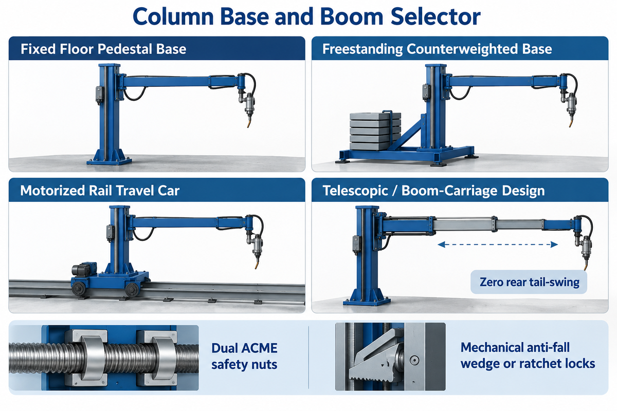
Mechanical anti-fall wedge or ratchet locks engage within
0.05–0.15 seconds
With hoist chain slack or overspeed. Dual ACME safety nuts provide continuous thread-wear backup on lead-screw masts per patent CN108941936A, and AMET Inc. engineering specifications. The right choice in column base and vertical lift safety architecture shields both shop floor space and operator’s life.
There are two types of vertical column lift Mechanical Engineering designs. Understanding these designs will aid in assessing why it costs double to install the same size screw system.
- Dual ACME Lead-Screw Architecture (AMET Style): A precision vertical ACME lead screw lifts the boom carriage at a fixed speed of
1,000 mm/min(39 in/min). Any thread wear transfers load to the backup nut and trips the drive brake. - Counterweight + Dual-Rope/Chain Hoist + Anti-Fall Ratchet (Key Plant / Pemamek / Aubrik Style): On heavy-duty towers (
3×3 m
to
15×15 m
), an internal cast-iron counterweight balances the boom carriage weight inside the mast. Dual duplex roller chains or wire ropes lift the saddle. An independent spring-loaded mechanical cam / wedge anti-fall device monitors the tension of the chains and locks onto the vertical safety rack.
It locks directly onto the vertical safety rack within10–20 mmif a chain stretches or parts.
A frequent plant layout failure occurs when buyers install a fixed-boom manipulator close to a shop wall or bay column. When a standard 5,000 mm horizontal boom retracts to weld a shell close to the mast, the rear tail protrudes 4,800–5,300 mm out the back.
If your shop aisle lacks rear tail-swing clearance, specify a telescopic boom that nests multi-stage tubes inside the saddle. You could also choose a boom-mounted motorized carriage with the welding head traveling on a stationary boom, as is used on LJ Welding boom-carriage cells.
| Configuration Type | Column Rotation (θ) | Floor Travel (Y-Axis) | Rear Tail-Swing Space Needed | Best Fabrication Bay Scenario |
|---|---|---|---|---|
| Fixed Floor Pedestal Base | Fixed (0°) |
None (anchored to pad) | Full boom stroke +600 mm
|
Dedicated single-bay circumferential & longitudinal station |
| Freestanding Counterweighted Base | Manual±90°or 360°
|
Forklift / crane relocatable | Full boom stroke +600 mm
|
Leased shops or multi-bay pipe welding without floor anchors |
| 360° Motorized Slewing Ring Base |
360°VFD slewing + lock |
Stationary pedestal | Circular radius =Sh + 700 mm
|
Dual-station layout serving two parallel turning roll beds |
| Motorized Rail Travel Car (Bogie) |
360°motorized + air/electric lock |
VFD rail travel50–3,000 mm/min
|
Full boom stroke +600 mm
|
Long wind towers (20–60 m) & multi-vessel growing lines |
| Telescopic / Boom-Carriage Design | Fixed or360°slewing |
Stationary or rail bogie | Zero rear tail-swing (≤400 mm) |
Tight shop bays where mast sits flush against a wall |
Matching the Welding Process Head: Single/Tandem SAW, GTAW/MIG, and Internal Bore Cladding
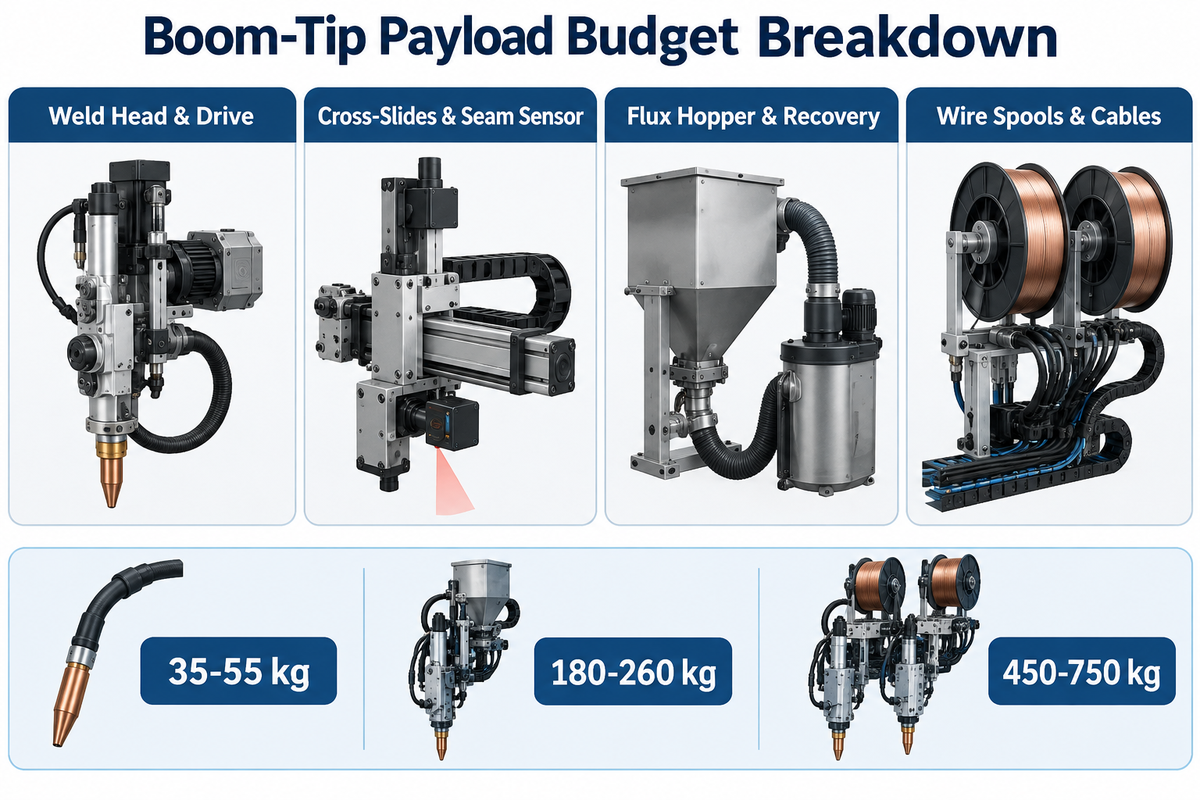
Total boom-tip package weight spans
180–260 kg
for single-wire submerged arc welding (SAW) and reaches
450–750 kg
for twin-wire SAW, with operator seat. These numbers are from Lincoln Electric, ESAB, AMET, and Aubrik integration catalogs. Sizing boom capacity using only the bare torch weight (
35–55 kg.
) overloads the cantilever by more than
200%
.
Different welding techniques impose vastly different mechanical and thermal loads on the boom machine in automated welding cells. In heavy submerged arc welding, mechanized stations raise arc-on duty time to
70–100%
compared to
25–40%
manual welding doesn’t require carrying heated flux hopper, but submerged arc does.
However, submerged arc requires carrying a heated flux hopper (50–100 L capacity) and a 5 HP vacuum flux recovery separator (as specified on AMET systems). The boom also supports heavy
25–30 kg
wire spools, motorized
±100 mm
cross-slides and thick copper power cables in the drag chain.
By contrast, a MIG welding manipulator (or oscillating TIG welding head) carries a lighter payload of
80–150 kg
To get the best out of your higher MIG deposition rates without flux hoppers. Even so, it demands zero high-frequency vibration along the boom so that the arc length and shielding gas column remain stable. As per Aboke’s engineering sizing rules, always add at least 25% payload headroom to your total measured boom-tip package weight at full extension. Table 5 lists every component weight for nine industrial configurations.
| Process Package / Sub-Assembly | Weld Head & Drive | Cross-Slides & Seam Sensor | Flux Hopper & Recovery | Wire Spools & Cables | Total Mounted Weight | Min Recommended Boom Rating (+25%) |
|---|---|---|---|---|---|---|
| 1. Single-Torch GMAW / MIG System |
22 kg
|
28 kg(oscillator + slide) |
0 kg(gas shielded) |
35 kg
|
85 kg |
150 kg(330 lbs) |
| 2. Cold-Wire / Hot-Wire GTAW (TIG) |
26 kg
|
34 kg(AVC + weave slide) |
0 kg(argon + chiller lines) |
40 kg
|
100 kg |
150 kg(330 lbs) |
| 3. Plasma Keyhole (PAW) Vessel Head |
35 kg
|
42 kg(laser + cross-slide) |
0 kg
|
48 kg
|
125 kg |
200 kg(440 lbs) |
| 4. Internal ID Bore Cladding Lance |
65 kg(lance + torch) |
35 kg(heavy base slide) |
0–30 kg
|
45 kg(+ camera monitor) |
145–175 kg |
300 kg(high overhang moment) |
| 5. Single-Wire SAW (Standard Hopper) |
45 kg
|
38 kg( ±100 mmslides + probe) |
65 kg(hopper + vacuum) |
52 kg( 25 kgreel + cables) |
200 kg |
300 kg(660 lbs) |
| 6. Single-Wire SAW (5 HP Heated Recovery) |
48 kg
|
45 kg(heavy cross-slides) |
105 kg(heated tank + separator) |
62 kg
|
260 kg |
350–400 kg
|
| 7. Dual-Head MIG + SAW Pipe Cell |
72 kg(root MIG + fill SAW) |
58 kg(dual independent slides) |
95 kg
|
85 kg(dual spools + cables) |
310 kg |
450 kg(1,000 lbs) |
| 8. Tandem Twin-Wire SAW (No Seat) |
95 kg(DC lead + AC trail) |
68 kg(heavy duty + laser) |
145 kg(pressurized + recovery) |
142 kg(dual drums/reels + cables) |
450 kg |
600 kg(1,320 lbs) |
| 9. Tandem SAW + Boom Operator Seat/Cab |
110 kg(narrow-gap tandem) |
75 kg
|
165 kg
|
150 kg+ 220 kg(cab + operator) |
720 kg |
1,000–1,200 kg
|
Column and Boom Manipulator vs. Welding Positioner, Turning Rolls, Gantry Welder, and 6-Axis Robot
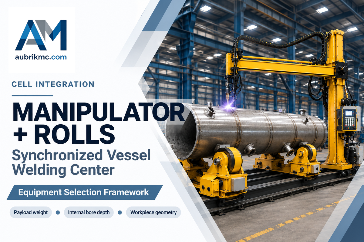
During circumferential vessel welding on turning rolls, the manipulator positions the torch
15–45 mm
At 12 o’clock top dead center. Molten slag and weld metal solidify without running, ahead of the arc. Capital expenditure committees frequently ask if a fabrication shop should purchase a column and boom manipulator, a gantry welder, a standalone positioner, or a 6-axis robotic arm.
The physical boundary comes down to three numbers: payload weight, internal bore depth, and workpiece geometry. A 6-axis articulated robotic arm typically carries only
10–25 kg
at the wrist. Its elbow collides with pipe walls when reaching deeper than 1,200–1,500 mm inside a shell. A column and boom carries 150–2,000 kg of submerged arc equipment and reaches 3,000–15,000 mm axially inside a cylinder. Conversely, when a flat plate panel or box girder exceeds 8,000–10,000 mm in width, cantilever boom droop favors a dual-column overhead gantry welder.
Dished heads, nozzles, and valves must be tilted and rotated simultaneously to accommodate various welding positions. For those parts, shops pair the manipulator with rotary welding positioners for flanged heads and nozzles. When sizing that companion turntable, follow our engineering formulas on rotary welding positioner torque and center-of-gravity sizing.
When Should You Combine a Column and Boom Manipulator With Self-Aligning Turning Rolls in a 1+2 Welding Center?
Combine one column and boom manipulator with two sets of self-aligning and conventional pipe welding rotators (rated from 2.5 ton to 150+ ton per bed) whenever your shop welds cylindrical shells in continuous multi-pass sequences.
In a 1+2 welding center, the manipulator mounts on a motorized rail travel car between two parallel roller beds. While the boom welds longitudinal and circumferential seams on Vessel A on Roller Bed 1, fitters load, tack, and preheat Vessel B on Roller Bed 2. Once Vessel A finishes welding, the column rotates 180° or indexes down the rail track to start Vessel B immediately. This layout doubles arc-on utilization and cuts crane waiting downtime by 40–55%.
40–55%
.
| Automation Architecture | Who Moves the Torch vs Workpiece? | Torch Payload Capacity | Max Internal Bore Reach | Primary Weld Joint Geometry | When to Specify / When to Avoid |
|---|---|---|---|---|---|
| 1. Column & Boom + Turning Rolls (1+1 / 1+2 Cell) | Boom moves torch (X/Z); rolls rotate shell (θ) |
150–2,000 kg
|
2,000–15,000 mm
|
ID/OD longitudinal & girth seams on cylinders | Specify: Tanks, pressure vessels, wind towers, pipes. |
| 2. Column & Boom + Rotary Positioner | Boom moves torch; positioner tilts (0–135°) & rotates |
150–800 kg
|
1,500–6,000 mm
|
Dished heads, hemispherical caps, valve bodies, nozzles | Specify: Complex flanged weldments needing tilt into 1G flat. |
| 3. Standalone Rotary Welding Positioner | Workpiece tilts/rotates; manual welder or fixed stand | N/A (workpiece load0.1–50 t) |
None (external access) | Short circular fillets, pipe flanges, elbows | Avoid: Long longitudinal seams (>1,000 mm) needing linear travel. |
| 4. Dual-Column Overhead Gantry Welder | Bridge & twin masts move torch across X/Y/Z |
500–2,500 kg
|
Zero ID reach (bridge blocks entry) | Wide bridge H-beams, ship stiffened panels, box girders | Avoid: Internal vessel seams where bridge cannot enter shell ID. |
| 5. Side-Beam Linear Welding Carriage | Carriage runs along fixed-height horizontal beam |
100–400 kg
|
External or fixed mandrel only | Single-diameter straight longitudinal seams | Avoid: Mixed tank diameters requiring frequent Z-height changes. |
| 6. 6-Axis Articulated Robotic Arm | 6-axis wrist moves GMAW/GTAW torch along 3D path |
10–25 kgwrist limit |
≤1,200 mm(elbow collision) |
Multi-angle structural brackets, nozzles, automotive frames | Avoid: Heavy SAW flux packages (>150 kg) or deep internal bores. |
| 7. Boom-Mounted Robot Arm (Hybrid Tower) | Column/boom acts as 3-axis macro positioner for robot |
250–600 kg(carries robot arm) |
3,000–8,000 mm
|
Large mining buckets, turbine casings, multi-nozzle shells | Specify: Large 3D weldments needing both long reach and 6-axis wrist. |
| 8. Magnetic Track Welding Bug / Tractor | Portable tractor climbs shell on magnetic guide band |
15–35 kg
|
Manual placement inside shell | Field storage tank erection, ship hull butts | Avoid: High-speed shop SAW requiring500 kgtandem flux recovery. |
| 9. Narrow-Lance Internal Cladding Manipulator | Stiffened alloy lance advances inside rotating pipe |
50–150 kg
|
1,500–4,500 mmin ≥280 mmID |
CRA / Inconel 625 internal pipe & valve bore cladding | Specify: Small-bore corrosion-resistant overlay where box booms cannot fit. |
Price Bands, Lead Times, Container Shipping Limits, and Supplier Selection Criteria
Standard manufacturing lead times run
45–90 days
for
2×2 m
to
5×5 m
column and boom manipulators. Custom welding cells above
6×6 m
require
100–150 days
. Ex-works equipment prices span
$8,500 to $135,000+ USD
(Estimated Q4 2026 (with prices fluctuations of steel and power source indices)). Knowledge about reasons for price differences, and ocean freight surcharges, will assist in budget overrun avoidance.
A critical logistics boundary ignored in generic buyer guides is the 40HQ ocean container dimensional limit. A standard 40-foot high-cube (40HQ) container has an internal length of
11,800 mm
, a width of
2,340 mm
, and a door height of
2,580 mm
. A manipulator with a
5,000–6,000 mm
vertical lift stroke has a total column height of
6,400–7,600 mm
and a broad base flange. One-piece welded masts with top pulleys attached, extending above
2,550 mm
width—or
10 m
masts exceeding
11.8 m
length—ship as out-of-gauge (OOG) cargo. That triggers
$8,000–$18,000 USD
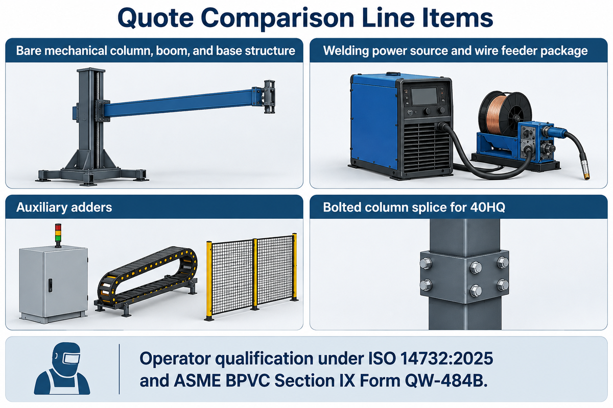
For flat-rack or open-top freight surcharges. Specify a precision-machined, dowel-pinned bolted column splice and bolt-on base outriggers on any tower above 5.0 m vertical stroke.
How Should You Compare Column and Boom Manipulator Quotes Across OEMs and System Integrators?
Compare quotes by breaking the lump-sum price into four separate line items. First, price the bare mechanical column, boom, and base structure. Second, separate the welding power source and wire feeder package (such as Lincoln Electric PowerWave, ESAB Aristo/LAF, or OEM 1,000 A / 1,250 A SAW rectifiers). List auxiliary adders.
Third, itemize auxiliary adders like motorized rail bogies, 5 HP heated flux recovery, seam tracking, and a welding manipulator video camera. Fourth, confirm operator qualification and safety docs.
Western turnkey integrators—such as Pemamek (PEMA), Key Plant Automation, LJ Welding Automation, and AMET Inc.—provide regional field service, pre-integrated Lincoln/ESAB/Fronius controls, and rental fleets. Their turnkey packages typically run
$50,000 to $160,000+ USD
Direct manufacturing OEMs such as Wuxi ABK Machinery (Aubrik) machine structural box girders, cold-drawn guideways and rolling beds in-house at ex-works prices of
$8,500 to $65,000 USD
They are equipped with globally serviceable Siemens/Schneider PLCs, Yaskawa/Delta VFDs and Lincoln or ESAB welding heads upon request. Regardless of supplier tier, verify that the control system supports operator qualification testing under ISO 14732:2025 (Edition 3, published June 2025) and ASME BPVC Section IX Form QW-484B. Simultaneous qualification follows ASME Section IX Appendix L.
| System Tier / Option Package | Direct OEM Ex-Works Range (USD) | Western Turnkey Integrator Range | Typical Lead Time | 40HQ Container Shipping Status |
|---|---|---|---|---|
| Compact Light Duty (2×2 m to 3×3 m, Bare Structure) |
$8,500–$15,000
|
$28,000–$48,000
|
30–45 days
|
Ships in 1× 20GP or 40HQ (disassembled mast/boom) |
| Medium Vessel Cell (4×4 m to 5×5 m + Single SAW + Recovery) |
$22,000–$42,000
|
$65,000–$110,000
|
45–65 days
|
1× 40HQ (requires bolt-off base outriggers) |
| Heavy Wind/Tank Tower (6×6 m to 8×8 m + Rail Bogie + Tandem SAW) |
$48,000–$95,000
|
$125,000–$240,000+
|
75–120 days
|
Requires machined bolted column splice for 40HQ |
| Option Adder: Motorized Rail Travel Car + 12 m Track |
+$3,800–$7,500
|
+$12,000–$22,000
|
Included in build | 6 m rail sections stack on container floor |
| Option Adder: 2-Axis Tactile Probe Seam Tracker + Cross-Slides |
+$2,800–$5,200
|
+$8,500–$16,000
|
Included in build | Packed in moisture-sealed wooden crate |
| Option Adder: Non-Contact Laser Vision Seam Tracker |
+$9,500–$18,500
|
+$22,000–$38,000
|
+15 dayscalibration |
Air-cushioned shock-mounted instrument case |
Integration & Utility Requirements: Power, Foundation Anchors, Seam Tracking, and RFQ Checklist
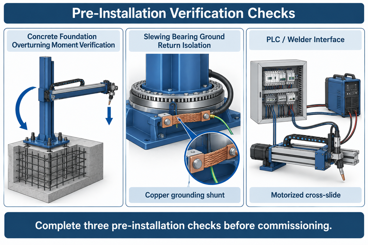
Heavy-duty manipulators require
0.5–0.7 MPa
dry compressed air at
300–600 L/min
when pneumatic flux recovery is mounted. Axis drives require
3–12 kW
of 3-phase power (
380V/50Hz
or
460V–480V/60Hz
(excluding the welding rectifier) according to industrial installation manuals. Completing three pre-installation checks and locking in your welding parameters prevents commissioning delays and bearing damage.
1. Concrete Foundation Overturning Moment Verification: A stationary column base must resist the full cantilever overturning moment
Moverturn = (Wboom · xcg) + (Wtip · Lmax)
with a safety factor of
≥2.5
. A
5×5 m
or
6×6 m
tower carrying a
600 kg
tandem SAW package requires a
300–500 mm
Thick reinforced C30/C35 concrete pad. Secure the base with chemical or J-hook anchor bolts (M24 to M36 Grade 8.8) tensioned to specification.
2. Slewing Bearing Ground Return Isolation: Never allow
600–1,200 A
Normal current flow through column slewing ring bearing or turning roll bearings upon submerged arc welding return. Stray current arcing across hardened steel ball raceways, causes micro-pitting and bearing seizure in weeks. Attach spring loaded copper grounding shoes on the rotating vessel shell. Install a copper grounding shunt across the column slewing ring, following our guide on high-current rotary ground return path design.
3. Seam Tracking & PLC Handshake: For carbon steel pressure vessels with clean bevel edges, a mechanical 2-axis tactile probe driving a
±100 to ±150 mm
motorized cross-slide holds the torch centered within
±0.25 mm
. For high-preheat alloy vessels (
150–250 °C
For preheat or variable gap fit-ups, specify a water-cooled laser vision tracker with adaptive fill control.
| Utility / Integration Parameter | Standard / Medium (2×2 m to 4×4 m) | Heavy / Extra-Heavy (5×5 m to 8×8 m) | Engineering Verification Requirement |
|---|---|---|---|
| 3-Phase Axis Drive Supply |
380V/415V/480V, 3.0–5.5 kW
|
380V/415V/480V, 7.5–15.0 kW
|
Dedicated breaker separate from1,000 ASAW rectifier |
| Compressed Air Supply |
0.5–0.6 MPa@ 250 L/min
|
0.6–0.7 MPa@ 450–600 L/min
|
Refrigerated air dryer required to prevent wet SAW flux |
| Concrete Foundation Pad |
250–350 mmC30 slab, 4–8× M24bolts |
400–600 mmC35 pile/pad, 8–12× M30/M36
|
Levelness≤1.0 mm/macross rail bogie track |
| Motorized Cross-Slide Stroke |
100 × 100 mm( ±50 mmY/Z) |
200 × 200 mmor 300 × 300 mm
|
Ball-screw drive with dust bellows and limit switches |
| PLC / Welder Interface | 24V DC dry-contact relay +0–10Vanalog |
Profinet / Modbus TCP / DeviceNet + encoder | Synchronized arc-start delay and crater-fill timer |
Engineering RFQ Specification Checklist (Copy & Send to Suppliers)
Including these 8 technical parameters in your Request for Quotation (RFQ) will result in the submission of accurate engineering drawings and avoidances of undersized boom proposals:
- 1. Vessel / Pipe Dimensional Range: Minimum and maximum shell outer diameter (
OD
), minimum internal diameter (
ID
), wall thickness (
t
), single-can length, and maximum vessel weight (tons). - 2. Turning Roll Bed Geometry: Existing or planned turning roll model, wheel diameter, center distance, and floor-to-shell bottom elevation (
Hroller
). - 3. Welding Process & Head Package: Single-wire SAW, tandem SAW, GMAW/MIG, hot-wire GTAW/TIG, or bore cladding. State power source brand and amperage (
1,000 A
or
1,250 A
). - 4. Total Boom-Tip Payload & Deflection Limit: Require rated payload capacity
≥1.25x
total mounted package weight. Require static vertical droop
<0.5 mm/m
at
100%
horizontal reach. - 5. Base & Boom Configuration: Stationary pedestal,
360°
motorized slewing ring, motorized rail travel bogie (state track length), or telescopic boom for zero rear tail-swing. - 6. Vertical Anti-Fall & Guideway Spec: Stipulate hardened cold-drawn or linear guideways. Demand a mechanical anti-fall ratchet arrestor or dual ACME safety nuts with wear switch.
- 7. Container Shipping Requirement: Require a precision-machined, dowel-pinned bolted column splice for vertical strokes
≥5,000 mm
to fit inside a standard 40HQ container. - 8. Shop Power & Qualification Standards: Specify plant 3-phase voltage and frequency (
380V/50Hz
or
480V/60Hz
). You must comply with ISO 14732:2025 and ASME Section IX QW-484B.
Frequently Asked Questions About Column and Boom Welding Manipulators
What is the difference between a column and boom manipulator and a welding positioner?
A column and boom manipulator moves the welding head along linear vertical and horizontal axes, whereas a welding positioner rotates and tilts the workpiece itself.
Per American Welding Society (AWS) definitions, the manipulator acts as a rigid three-axis torch carrier spanning 2,000–15,000 mm. Conversely, a rotary positioner or rotator clamps weldents weighing
100 kg to 50+ tons
on a motorized turntable. That turntable tilts
0–135°
and rotates
360°
, to assemble complex nozzles and heads into the flat 1G downhand welding position for high-deposition welding passes.
Can small welding manipulators be used for automatic internal pipe welding?
Yes, small welding manipulators perform automatic internal pipe welding when fitted with a compact boom or narrow reach lance that clears the pipe bore.
Standard compact box booms (
220 × 180 mm
cross-section) enter pipe spools with internal diameters of
550–650 mm
or larger. For smaller pipes down to 280–450 mm ID, fabricators bolt a tubular alloy reach lance onto the boom tip. The flux hopper and wire feeder are externally mounted on the rear saddle. Internal root and fill passes are controlled by a weld camera with a video demonstration monitor.
How do you prevent welding ground current from damaging the column slewing bearing?
Prevent slewing bearing arc damage by clamping spring-loaded copper ground shoes onto the workpiece and isolating the welding return path from the mast.
Submerged arc welding currents of 600–1,200 A pit hardened bearing raceways if return current travels through the boom into the column slewing ring. To alleviate this, add phenolic dielectric insulation pads to the welding head mount to stop the stray return current. Secure the column base to the shop earth grid with copper straps, and check the contact resistance of the ground clamps before striking an arc.
What role does a motorized cross-slide play on a column and boom welding head?
A motorized cross-slide provides fine two-axis (Y/Z) micrometer adjustment at the boom tip to keep the torch centered in the groove.
Offering 100 × 100 mm to 300 × 300 mm of ball-screw stroke, the cross-slide receives real-time signals from a tactile probe or laser seam tracker. Additionally, it compensates for drift of the axial vessel in the Z-axis. It does so without moving the main column mast.
What is the typical horizontal boom travel speed range for submerged arc welding?
Industrial horizontal boom travel speed spans 50 to 1,200 mm/min for precision welding and up to 3,000 mm/min for rapid positioning.
Closed-loop AC VFD rack-and-pinion drives hold speed ripple within
±1%
across single-wire SAW (
350–650 mm/min
) and tandem twin-wire SAW (
700–1,400 mm/min
) passes.
How often should vertical lift chains, counterweights, and anti-fall locks be inspected on a heavy-duty manipulator?
Operators must visually check lift chains and limit switches before every shift, while maintenance engineers perform wear and drop tests every 500 hours.
During the daily pre-shift walkaround, check duplex roller chains or wire ropes for flux dust, broken links, and balanced counterweight tension. On ACME screw masts, measure bronze primary nut axial backlash and test the secondary safety nut electrical interlock switch.
Every 12 months, run a no-weld mechanical trigger test of the spring-loaded anti-fall ratchet pawl. The cam jaws must bite cleanly into the vertical safety rack within 15 mm of travel.
15 mm
of travel.
Need a Custom Stroke & Turning Roll Layout for Your Vessel Bay?
Configuring a compact
3,000 × 3,000 mm
single-wire SAW station or a rail-traveling
6,000 × 6,000 mm
Our growing-line center requires exact clearance verification. Wuxi ABK Machinery (Aubrik) can provide factory-direct 2D/3D general arrangement drawings, container-spliced heavy masts and full FAT deflection reports. Please explore our complete column and boom manipulator lineup or send your shell dimensions to our engineering team for a custom proposal.
References & Sources
- American Welding Society (AWS) — Welding Digest: The Future of Fabrication (Manipulator vs. Positioner & AWS D16 / CRAW Mechanized Welding Framework). (October 2026). Available at https://www.aws.org/magazines-and-media/welding-digest/2026/october/the-future-of-fabrication/
- American Welding Society (AWS) — Practical Reference Guide to Positioning (PRGP2008PV): Welding Head Manipulators and Turning Rolls. Available at https://files.aws.org/technical/errata/PRGP2008PV.pdf
- International Organization for Standardization (ISO) — ISO 14732:2025 (Edition 3, June 2025): Welding personnel — Qualification testing of welding operators and weld setters for mechanized and automatic welding of metallic materials. Available at https://www.iso.org/standard/82980.html
- American Society of Mechanical Engineers (ASME) — BPVC Section IX: Welding, Brazing, and Fusing Qualifications (Form QW-484B & Appendix L Mechanized Operator Qualification). Available at https://www.asme.org/codes-standards/find-codes-standards/bpvc-ix-bpvc-section-ix-welding-brazing-fusing-qualifications
- The National Board of Boiler and Pressure Vessel Inspectors — Simultaneous Qualification of Welding Operators under ASME Section IX Appendix L and ISO 14732. https://www.nationalboard.org/Index.aspx?pageID=164&ID=470
- U.S. Navy Naval Facilities Engineering Systems Command (NAVFAC) — NAVCRANECENINST 11450.2A: Column and Boom Support Drift and Rotational Inertia Torque Safety Guidelines. https://navfac.navy.mil/Portals/68/Documents/Business-Lines/Weight-Handling/WH_ Docs/NAVCRANECENINST_11450.2A.pdf
- The Fabricator / The Welder (FMA Communications) — Two Slings, Controlled Rotation Increase Welding Manipulator Safety and Speed Control (10 FPM Positioning vs. 6 -30 IPM Welding Cruise). https://www.thefabricator.com/thewelder/product/arcwelding/two-slings-controlled-rotation-increase-welding-manipulator-safety
- China National Intellectual Property Administration / Google Patents — Patent CN108941936A: Anti-Falling Mechanism for Longitudinal Seam Welding Manipulator. https://patents.google.com/patent/CN108941936A/en
- China National Intellectual Property Administration / Google Patents — Utility Model CN211387216U: Heavy-Duty Welding Manipulator Column and Boom Anti-Deflection and Guideway Preload Mechanism. https://patents.google.com/patent/CN211387216U/en
Trending now