Get in Touch with Aubrik Company

Aubrik Column and Boom Welding Manipulator
Modular 4-Model Lineup (2×3 m to 5×6 m) for SAW, MIG, TIG and FCAW Automation
Engineered for tank, pressure vessel, wind tower and structural steel fabricators who need stable torch positioning at scale. Four standard models, customizable stroke and 110–600 V global power, ISO 9001 + CE certified.
System Specifications
4 Standard Models
(2×3 → 5×6 m)
(2×3 → 5×6 m)
5 Welding Processes
(SAW/MIG/TIG/FCAW/PAW)
(SAW/MIG/TIG/FCAW/PAW)
ISO 9001 + CE Certified Quality System
1 yr Free Warranty
+ Global Service
+ Global Service
1,000 Welding Units
Annual Capacity
Annual Capacity
8+ International Markets
Served
Served
Equipment Availability
Searching for a column and boom welding machine, sub arc manipulator, or column and boom welder for sale? You’re in luck. Every Aubrik model detailed below is custom made to your specifications. Both the 23 entry frame and the 56 heavy-duty platform are available for quote today.
[SYS-00] PROCESS INTEGRATION
Why Manual Welding Slows Down Tank, Pipe and Wind-Tower Production — and How Aubrik’s 5-Axis Manipulator Answers
STANDARDS REF: ISO 3834 — Quality requirements for fusion welding (iso.org) // USPTO US 12053844 — Welding manipulator (patents.google.com)
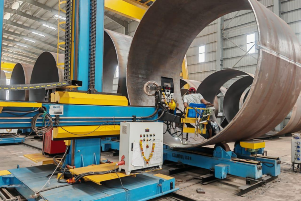
torch manipulation, at scale. A column and boom welding manipulator enables continuous positioning of the welding torch along long, repeated seams without operator reach or climbing fatigue. The base of the column drives traverse and rotation while the horizontal boom moves the weld head across vessels, tanks and other structural elements that manual positioning cannot effectively manage. US-based fabricators of 30-ton ASME pressure vessels and EU customers building 80-ton wind tower sections can employ the same Aubrik manipulator hardware architecture.
[ENG-01] CORE MECHANISM
What an Aubrik Column and Boom Welding Manipulator Does
Each Aubrik manipulator is fabricated with a common platform and incorporates these five engineered components: an industrial column with a traverse base, a horizontal boom with V-guide rails, a motorized trolley, an integrated industrial control system and oil-bath lubrication system. torch positioning then becomes a software command where boom elevation, extension, column rotation, and traverse speed can be accurately controlled by step-less variable frequency drives.
After the operator sets parameters one time, the Aubrik manipulator precisely reproduces this exact profile for meters upon meter of weld. Our EU buyer base consistently ranks rigid frame design as the primary reason for the 5+ year mean time before failure on our 24-hour production machines. This stable platform elevates processes such as SAW, MIG/MAG, TIG, FCAW and plasma from skilled craft into efficient welding automation systems. What follows breaks down each of the five elements responsible.
[DIAG-02] FAILURE ANALYSIS
Manual welding fails three places in heavy fabrication shops:
-
Fatigue-induced seam quality decline
Long circumferential seams in a 3-m diameter vessel extend 9-10 meters/pass. Manual positional accuracy degrades quickly after the first pass. -
Long-seam travel speed limitations
Operators can’t maintain 1-mm torch positioning at the typical 150 in./min. (3810 mm./min.) industrial SAW travel speed. -
Operator safety on tall workpieces
welding above 2 m without remote positioning means scaffolding, fall arrest gear and shift productivity loss.
[DATA-03] THROUGHPUT METRICS
The throughput gap manual welding leaves on the floor
Studies in welding automation indicate reduced setup times (as much as 25% reduction) and improved welding efficiency (approximately 30% gain) when manipulators replace manual placement for repetitive long seams. Individual-wire submerged arc welding (SAW) offers deposition rates from 16-60 lbs/hr; tandem-wire SAW is approximately 30% higher – production that a manually positioned welder can’t achieve on large circumferential or linear welds.
[APP-04] FIELD APPLICATION
Concrete example — long longitudinal seam on a 6 m boiler shell
A 6 m long, 2.4 m diameter boiler pressure vessel shell needs an Aubrik 5×6 frame running SAW down the entire length at 700 mm/min. Trolley travel covers the seam in roughly 9 minutes per pass, holding ±0.4 mm torch position relative to centerline. Manual SAW using comparable wire diameter would force a welder to walk the length, climb scaffolding for the upper half and re-strike the arc twice — extending the same seam to 35–45 minutes per pass, with measurable porosity drift in the unsupervised middle third.
The Aubrik Manipulator System — 5 Engineered Components and What Each Does
The five independent core sub systems from which each Aubrik column and boom manipulator is manufactured are field-replaceable, allowing future upgrades to seam tracking, flux recovery or remote wireless operation to be implemented without disassembling the frame.
SYS_01
1. Column (Vertical Backbone)
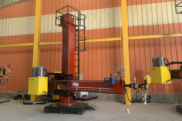
The column supports the boom and welding head. Verify the load rating, holding brakes, and anti-fall protection for the selected configuration; an anti-fall device is intended to arrest the boom if the lifting mechanism fails. Two speed, 180deg motor driven rotation comes standard with the 34, 45 & 56.
4 Standard Models from 2×3 m to 5×6 m — Spec Table and Sizing Decision Matrix
Sizing references: ASME Section VIII Div.1 (asme.org) pressure-vessel geometry tolerances · ISO 3834 (iso.org) fusion welding quality requirements.
Aubrik’s standard manipulators come in four column sizes (34″, 45″, 56″, and 72″) and the standard boom welding manipulator frames (22″, 34″, 45″, and 56″). We ship these frames standard with out-of-the-box support for SAW or MIG/MAG; a TIG, FCAW, or plasma option will easily bolt-on at any point in your manipulator’s life. Of the EU and US buyers that we serve, about 80% small/medium shop space is taken up by 34″ and 45″ frames that handle less than 30 ton tanks, or spooled piping that is shorter than 4m.
Full Specification Table — 4-Tier Modular Sizing Matrix
| Model | Lifting Range (mm) | Retracting Range (mm) | Lifting Speed (mm/min) | Retracting Speed (mm/min) | Max Boom-End Load (kg) | Column Rotation | Trolley Speed (mm/min) | Rail Inner Span (mm) |
|---|---|---|---|---|---|---|---|---|
| 2×3 | 2,000 | 3,000 | 300 | 120–1,200 | 60 | Manual | Manual | 1,000–2,000 |
| 3×4 | 3,000 | 4,000 | 1,000 | 120–1,200 | 80 | ±180° | 3,000 | 1,200–2,500 |
| 4×5 | 4,000 | 5,000 | 1,000 | 120–1,200 | 80 | ±180° | 3,000 | 1,200–3,000 |
| 5×6 | 5,000 | 6,000 | 1,000 | 120–1,200 | 100 | ±180° | 3,000 | 1,500–3,000 |
Every parameter we specify below is based upon Aubrik’s stock product line; customized stroke, capacity, or power options are available (see the purchase guide below).
Sizing Decision Matrix — Right-Size, Not Max-Size
The most common equipment acquisition failure: Purchasing a frame with more working room than the physical workpiece or pipeline diameter. Extra manipulator capacity on your floor eats up time while your booms traverse longer idle paths, significantly impacting overall output efficiency.
| Workpiece Class | Typical Diameter / Length | Recommended Model | Notes |
|---|---|---|---|
| Small pressure vessels, utility tanks, prototyping | ≤ 1.8 m diameter / ≤ 3 m long | 2×3 | Manual rotation; entry-level SAW or MIG |
| Mid-range tanks, chemical vessels, short pipe spools | 1.8–3 m diameter / 3–4 m long | 3×4 | Motorized rotation; SAW + MIG dual-process common |
| Petrochemical vessels, mid-size ship hull sections, wind tower flanges | 3–4 m diameter / 4–5 m long | 4×5 | Most common heavy-duty configuration |
| Large wind tower sections, big-bore pressure vessels, large boiler shells | 4–5 m diameter / 5–6 m long | 5×6 | Heavy-duty; integrates with turning rolls 30+ ton |
SYS-01 Architecture
Process Compatibility — MIG/MAG, TIG, SAW, FCAW and Plasma in One Frame
Buying a manipulator that only runs one process, like SAW, is the classic single-process trap — a procurement risk we see repeatedly. One year after purchase, the day your shop adds a stainless contract or a thick-section FCAW job, you face the hidden expense of a second machine. What makes those frames inflexible is rigid geometry locked to a single welding head.
Aubrik engineers each frame process-agnostic — with built-in rigidity and smooth stepless motion control, the 4×5 manipulator that runs submerged arc on a wind tower today switches to TIG on a stainless heat exchanger tomorrow, given the right TIG head and power source. Buying a process-flexible frame is key because effective equipment life extends through the entirety of your work.
DAT-02 Performance Matrix
Welding Process Compatibility Matrix
| Process | Material Range | Typical Thickness | Best-Fit Industries | Deposition Rate |
|---|---|---|---|---|
| SAW (Submerged Arc) | Carbon steel, low-alloy steel, stainless | 6–80 mm+ | Pressure vessels, wind towers, shipbuilding | 16–60 lbs/hr (single wire) ¹ |
| MIG/MAG (GMAW) | Carbon steel, stainless, aluminum | 1.5–25 mm | Structural steel, automotive parts, pipe spools | 3–15 lbs/hr ¹ |
| TIG (GTAW) | Stainless, non-ferrous, exotics | 0.5–10 mm | Aerospace, medical, food & pharma | 0.5–3 lbs/hr |
| FCAW (Flux-Cored) | Carbon steel, low-alloy, dissimilar | 3–40 mm | Heavy machinery, offshore, repair welding | 5–20 lbs/hr |
| PAW (Plasma) | Stainless, titanium, nickel alloys | 0.1–8 mm | Aerospace bore cladding, precision tube | 1–4 lbs/hr |
Dual-process combinations — TIG/PAW root, SAW fill, MIG cap — are common on the 4×5 and 5×6 frames. Quick-change tooling on the cross slide lets the boom switch heads while the trolley indexes between seams.
APP-03 Integration & Cases
Scenario — Stainless Heat Exchanger Audit
VISUAL_FEED

For a 1.8 m diameter, 12 mm wall stainless heat exchanger shell, an industrial buyer in southern Europe runs an Aubrik 3×4 frame: TIG-GTAW at 200 mm/min on the root for food-grade weld geometry, then quick-changes to a SAW head at 800 mm/min for fill and cap.
Each shell carries roughly 18 m of welded seam (two circumferential + four longitudinal) and weighs in around 3 ton; cycle time runs under 4 hours including head changeover, versus 11–14 hours for fully manual TIG on the same joint.
Request a Custom GuideIntegration with Positioners
SYS_MONITOR
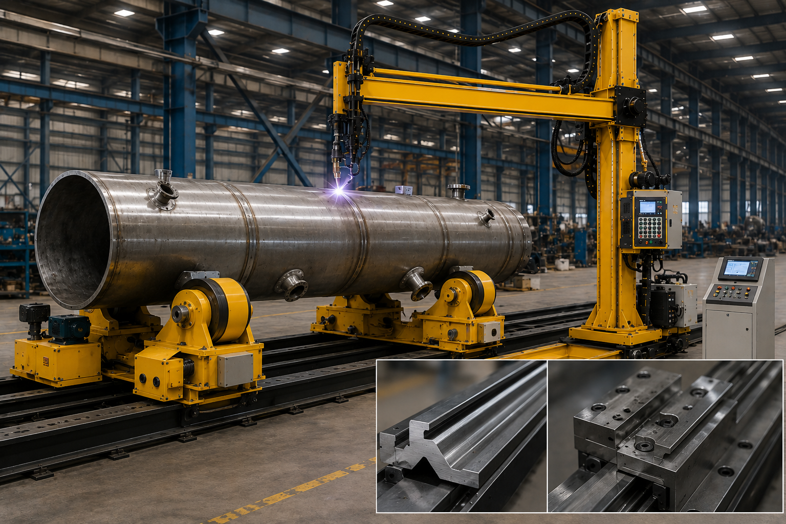
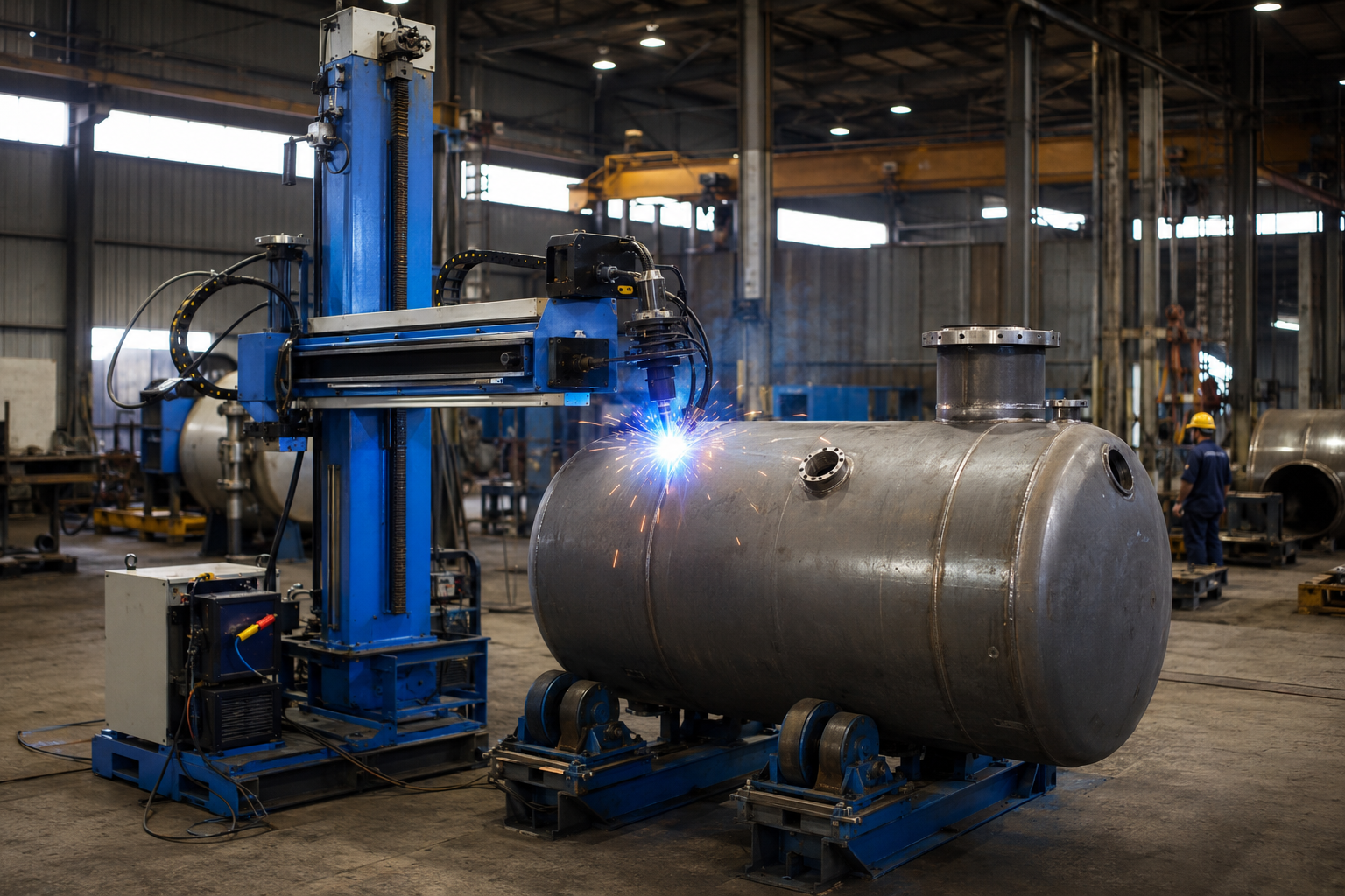
For cylindrical workpieces the manipulator pairs with welding positioners or turning rolls. The positioner rotates the workpiece under a stationary torch while a column and boom acts as head holder.
“We pre-treat each boom guide rail in 4 separate stages – it gets V-shaped, machined, and heat-treated… it’s why a 4m boom maintains 0.5mm torch positional accuracy through a full retraction.”
¹ Deposition rates reflect industry averages for the process class; actual output depends on wire diameter, current, voltage and shielding gas.
Industries We Serve — Pressure Vessels, Shipbuilding, Wind Towers and Heavy Machinery
Industry standards: ASME Section VIII Div.1 (asme.org) · ISO 9001:2015 (iso.org) quality management
Aubrik manipulators find deployment into 5 major fabrication industries, each a niche application with unique geometry, weld standards, and frame-size preferences. The subsequent cards describe the position of our four main models based on industry-specific seam lengths, deposition rates and recent case studies. Industrial buyer profiles range from small/medium regional fabricators ordering single 2×3 frames to EU buyer and US buyer OEMs deploying multi-unit lines for 100 ton+ wind tower assembly.
 [IND-01] CORE SECTOR
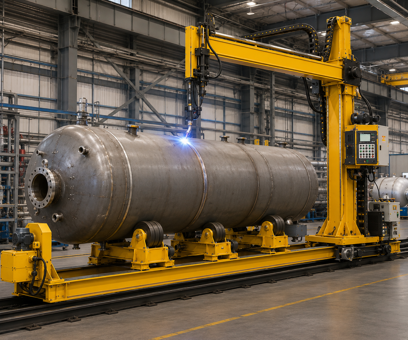
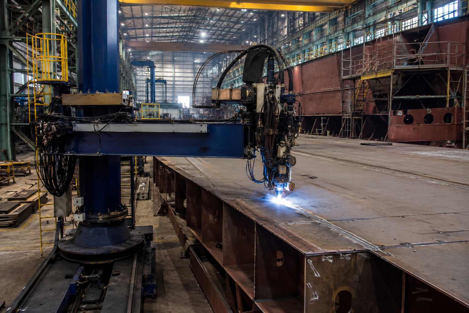
Petrochemical & Pressure Vessel
Tank, Pressure Vessel, Chemical Pipeline Fabrication. Full 180 column rotation provides circumferential and longitudinal seam welding.
SPEC: Recommended equipment: 34, 45, and 56 Aubrik systems with SAW for thick wall efficiency.
[IND-02]
Shipbuilding & Offshore
Offshore Structures & Marine Fabrications (ship and hull sections, deck plating, platform modules) Heavy lift capability (80-100 kg) at boom-end, SAW compatibility make this the solution for high-productivity long longitudinal hull seams.
SPEC: Recommended equipment: 45, 56 systems.

[IND-03]
Wind Energy
Wind Tower Parts. consistent torch positioning over 4-5m sections. the most important aspect for any manipulator.
SPEC: We recommend 45 or 56, especially if using our turnable rolls.
[IND-04]
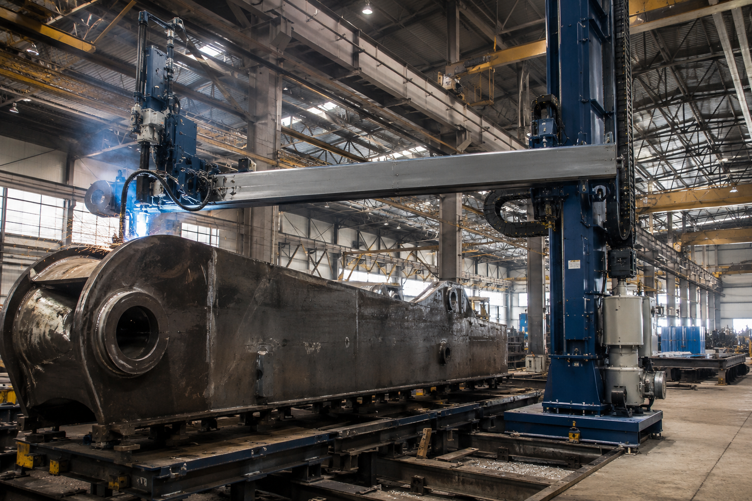
Heavy Machinery & Construction
Crane arms, boom components, large structural sections. Stroke range allows varied part sizes; FCWA process on our manipulator is well suited to heavy structural work in accordance with AWS D1.1.
SPEC: Recommend: 45 or 56.
[IND-05]
General Manufacturing
fabrications for smaller tanks and utility vessels.The lowest priced model is 23. this is for the workshop looking to step-up from 100% manual or a budget basic entry level for SAW/MIG welding processes.
SPEC: recommend 23.
[CASE SCENARIO]
Scenario — Brazilian wind tower assembly line
A major Brazilian wind tower manufacturer utilized 3 units of our 56 Aubrik manipulators with integrated 80 ton capacity turning rolls for production of wind turbine tower sections, with each section being 100m long and requiring some 38 linear meters of longitudinal SAW and 3 short circumferential welds. With 180 degree column travel and no workpiece movement, each assembly line produced approximately two complete sections per shift, compared to a single section at our prior fixed cell operation.
[SYS-REG-QA // CONFIG.2026]
Certifications, Standards Compliance and Quality Assurance
All Aubrik manipulator columns and all Govujib column supports are built under a CE marking EU compliant quality management system, certified and tested to ISO 9001 standards, covering all stages from manufacturing and assembly through post sale service. We certify every export shipment with a Certificate of Conformity and offer customer QA “Fast Track” audit support that allows for buyer closure in as little as 7 days for standard 30ton manipulator configurations.
QA-01
ISO 9001 Quality Management
QA-02
CE Marking (Machinery Directive)
QA-03
1-Year Warranty (All Units)
QA-04
Global OEM Service
[CONSOLE-LEFT // TECHNICAL STANDARDS]
Standards Our Equipment Is Designed to Support
Manipulation for torch positioning & drive Speeds support qualified procedures for structural fabrication and erection.
Longitudinal and circumferential welds may comply with ASME Section VIII Div. 1 geometry specifications where used with qualified procedures to ASME Section IX.
The SAWS automation we use is compliant to API standards.
provides documented evidence of welding process controls and quality systems where this code is required.
[CONSOLE-RIGHT-A // BOUNDARY SCOPE]
What the certification covers — and what it does not
ISO9001 + CE cover equipment design, quality, manufacturing & machinery safety – codes (e.g., ASME, API, AWS) apply to weld procedures and welders themselves. Aubrik provides support for welder & equipment qualification but does not substitute; compliant fabrication demands both aspects.
[CONSOLE-RIGHT-B // AUDIT CASE STUDY]
Scenario — Spanish petrochemical vessel procurement audit
A large petrochemical OEM in Spain evaluated 3 SAW welding manipulator suppliers in early 2025 for a substantial ASME Section VIII Div.1 vessel build. Aubrik delivered its 45 manipulator with an eu 380V/50HZ/3-Ph setup including a declaration of Conformity and copy of its iso 9001 certificate in the first container to arrive, which allowed the customer’s quality group to close their supplier certification in under one week – from weeks to days.
// DISPATCH DATA LOG “Certificate paperwork is often overlooked by busy overseas buyers as one of the easiest way to shorten procurement time lines.”
[DOC-REF // ID-WTM-2026]
Procurement Guide — Lead Time, Customization, Power Configuration (110–600 V Global)
For most procurement operations, there are three things they will need to get a RFQ to the welding manipulator manufacturer prior to making commitment: A list of all the custom requirements in an clear format. A feasible structure for the lead times, and reassurance that they will work with existing voltage without modification or re-tooling, and this guide addresses each of those issues. Whether your an E.U. buyer who is building a 30 ton program, a US buyer erecting 80 ton wind tower, or a small to medium regional industrial purchaser who is evaluating your initial automation step, use the same basic R.F.Q. template.
Customization Options Standard on the Aubrik Product Line
- STROKE
The range between the lowest down position and highest retract positions is not standard within the 23 to 56 envelopes; please define for your request.
- WIRELESS
A wireless pendent control is available to replace the 12m wired pended for operator safety when working on tall parts.
- RECOVERY
Flux Recovery system; optimum for use with SAW; it’s attached to the boom-end head.
- CAMERA
Monitoring with camera – remote observation arc at locations of difficult accessibility in a seam.
- TRACKING
The latest in tactile and laser seam tracking for long circumferential welds provides true closed-loop seam tracking.
- OSCILLATION
Programmable oscillation with wider control range for weld bead cross slide.
- BRANDING
OEM branding: full private-label program for our distributor and integrator partners
- TRACK RAIL
Travel rail length – extended rails beyond standard inner span upon request
[DATA-GRID]
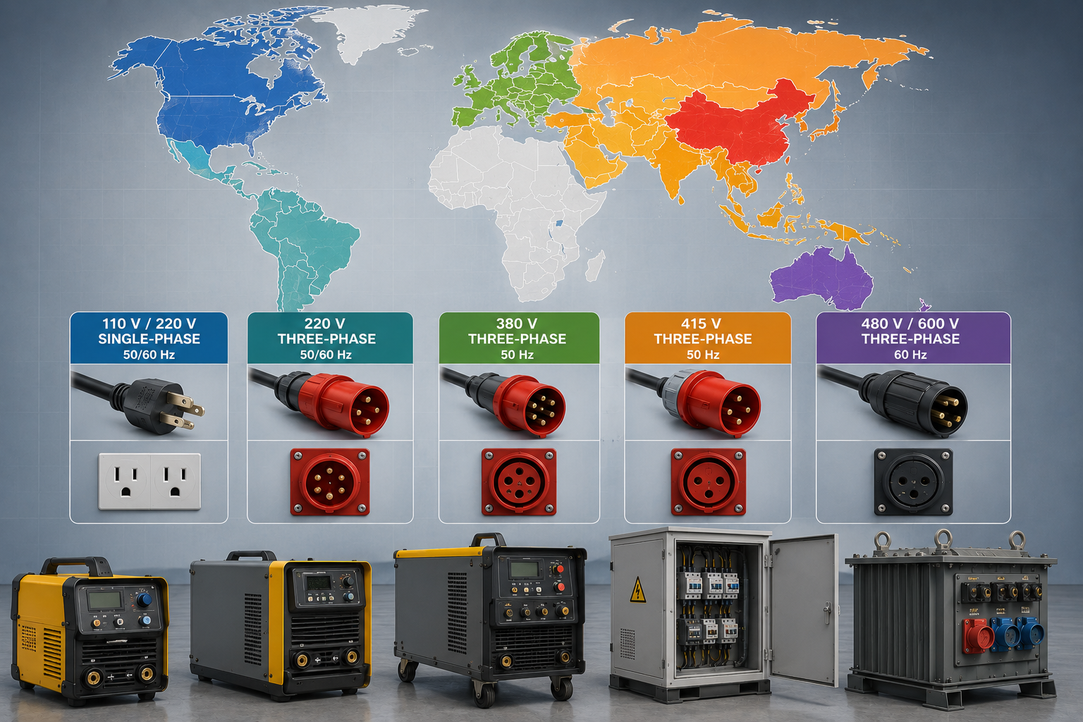
Power Source Configuration for Global Markets
| Voltage | Frequency | Common Markets |
|---|---|---|
| 110 V / 220 V single-phase | 50/60 Hz | Light-duty US, parts of South America |
| 220 V three-phase | 50/60 Hz | Brazil, parts of Southeast Asia |
| 380 V three-phase | 50 Hz | EU (Spain, Germany, France, Italy), China |
| 415 V three-phase | 50 Hz | UK, India, Australia |
| 480 V / 600 V three-phase | 60 Hz | US, Canada |
[CASE-LOG]
Scenario — what a complete RFQ to a welding manipulator manufacturer should specify
What will the quotation take – for a typical 45 frame quote – for a full RFQ, there’s a total of 8 different input variables – a maximum workpiece length and diameter; main welding method (SAW, MIG, TIG, FCAW), the available local voltage and frequency; required peripherals (wireless remote, flux recovery, seam tracking, camera); a shipment port and Incoterm; plus any certification documentation that will be required by customs.
// TIMELINE AUDIT
Armed with those 8 inputs Aubrik will then issue, the client, the documentation that they require in the form of a build sheet, a lead time broken down by milestone and a unit by unit quotation all inside 5 working days – the biggest factor that causes weeks of back-and-forth is the absence of a input.
[CRITICAL-PATH]
What drives lead time in your quote
Because a basic 4-model build is more predictable, 4-model ships much faster than custom-stroke and non-standard voltage equipment. Biggest wildcards: accessory selection (seam-tracker, remote pendant, camera kit), shipping mode and your local import paperwork needs. Every Aubrik quote breaks lead time into build, accessory integration and shipping windows, so procurement can plan against real milestones rather than a single black-box number.
Production Line Interactive Evaluation Tools
MODULE 01 // CAPEX
Workshop Cost Calculator
Evaluate capital expenditure for your steel structure workshop. Input dimensional parameters to generate an initial baseline cost estimate for facility construction and primary structural framework.
Launch CalculatorMODULE 02 // LOGISTICS
Span & Crane Workflow Selector
Optimize heavy material handling logistics. Configure workshop span width against required bridge crane lifting capacities to determine the most efficient structural grid and production workflow layout.
Configure WorkflowMODULE 03 // ROI
TCO & Payback Calculator
Assess long-term profitability and equipment amortization. Calculate Total Cost of Ownership and estimate the ROI timeframe by factoring in production throughput gains and automation efficiency.
Calculate ROIFrequently Asked Questions
Three numbers to begin with; biggest workpiece diameter, longest seam, your workshop crane clearance height. Add 200mm to workpiece height for lift height; add 500mm to your longest seam for retraction range. Choose the smallest frame size which will fit within your envelope; bigger just creates lost travel time.
The frame is process-neutral. Whether SAW, MIG/MAG (GMAW), TIG (GTAW), FCAW or PAW, they are all mounted on one and the same chassis. Dual-process machines – TIG root + SAW fill – are in the standard on 45 and 56 frames using changing tool on the carriage.
An anti-fall device for locking the boom in case the lifting chain breaks, mechanical limit switches at the end stops of the boom extension and elevation range and protection circuits with overload, overcurrent and undervoltage functions at the electrical components in the imported frequency converters are all incorporated on all manipulators. On the heavy-duty 56 frames installed in the close vicinity of a vertical- cylindrical pressure vessel, a dual rope anti-fall system or the counterbalance brake assembly at the outer extremity of the boom represents an extra mechanical protection layer, provided as specifically desired by the EU clientele the pressure vessel exceeding 4 m in diameter. Optional wireless control pendant and camera provide a direct decrease in the operator exposure time at the weld areas and the option to access remotely from a control panel the settings and control of two cells, each located inside of a cell belonging to different safety areas of the process section.
SAW or MIG operators with a few months of experience should have the unit up and running within two days; the pendant – wireless or hard-wired – accesses all weldning and travel- speed control functions on one screen so they dont have to memorize the differences between, say, the speed controller and the arc-voltage knob. Routine maintenance typically consists of a monthly look for the right lube levels, and a once a quarter check for limit switch operation – a feature, like grease points, other suppliers leave to the operator because the units fully enclosed, oil-bath lubricating system excludes weld particulate and arc fumes.
Custom stroke builds are quoted on a project basis. Confirm the availability and compatibility of options such as wireless control, flux recovery, seam tracking, camera systems, OEM branding, travel-rail extensions, oscillators, and custom voltage for the proposed build. Submit your requirements with the RFQ so the quotation can be accompanied by a build sheet.
For the average workshop, the usual 12m hardwired pendant is perfectly acceptable. But there are two scenarios where wireless communication of sorts is needed: first, is if your workpiece is so high that you’ll need space away from the arc. second, is if your manipulator works in a joint bay, you don’t need to leave yourself on a loose and potentially tripping cable. Typical distances are what they claim (designed for an industrial bay size).
A robotic welding system uses a 6-axis articulated arm for complex 3D paths — automotive components, small fixtures, weldments with many short seams. A column and boom manipulator is purpose-built for long, repetitive 2D seams — tank circumferential welds, wind tower longitudinal seams, pipe spool ends. For SAW on large-diameter workpieces, the manipulator delivers higher deposition rate per CAPEX dollar than a robot covering the same envelope.
yes – this is the standard setup with cylindrical products. Tailzeys (we now call this the Welding Tapelej) and Turning Rolls turn the product and the Manipulator keeps the torch stationary. We also have the capability of moving the torch with the trolley for longitudinal welding. Aubrik also manufacture Head and Tailstock Talezeys & turning rolls as a full welding station package.
Our control system runs from 110 V to 600 V, matching any common industrial voltage standard. EU customers usually order 380 V three-phase 50 Hz, US customers run 480 V or 600 V 60 Hz, and UK/India/Australia use 415 V. Specify your local voltage and frequency in the RFQ — your build is set at the factory before shipping, not after.
Every Aubrik unit will be delivered with a full operating manual, a declaration of CE conformity, copy of ISO9001 certificate and one year free parts and labour warranty. Genuine spare parts will ship from our Wuxi facility pursuant to a written service agreement. All of our foreign-language technical support is performed by English-speaking engineers remotely diagnosing our machines – within about 24 hours of the first notification of the problem. Where on-site commissioning is required, our on-field engineer will be assigned to your country, with all of his travel and logistics costs incurred by our OEM customization agreements.