Get in Touch with Aubrik Company

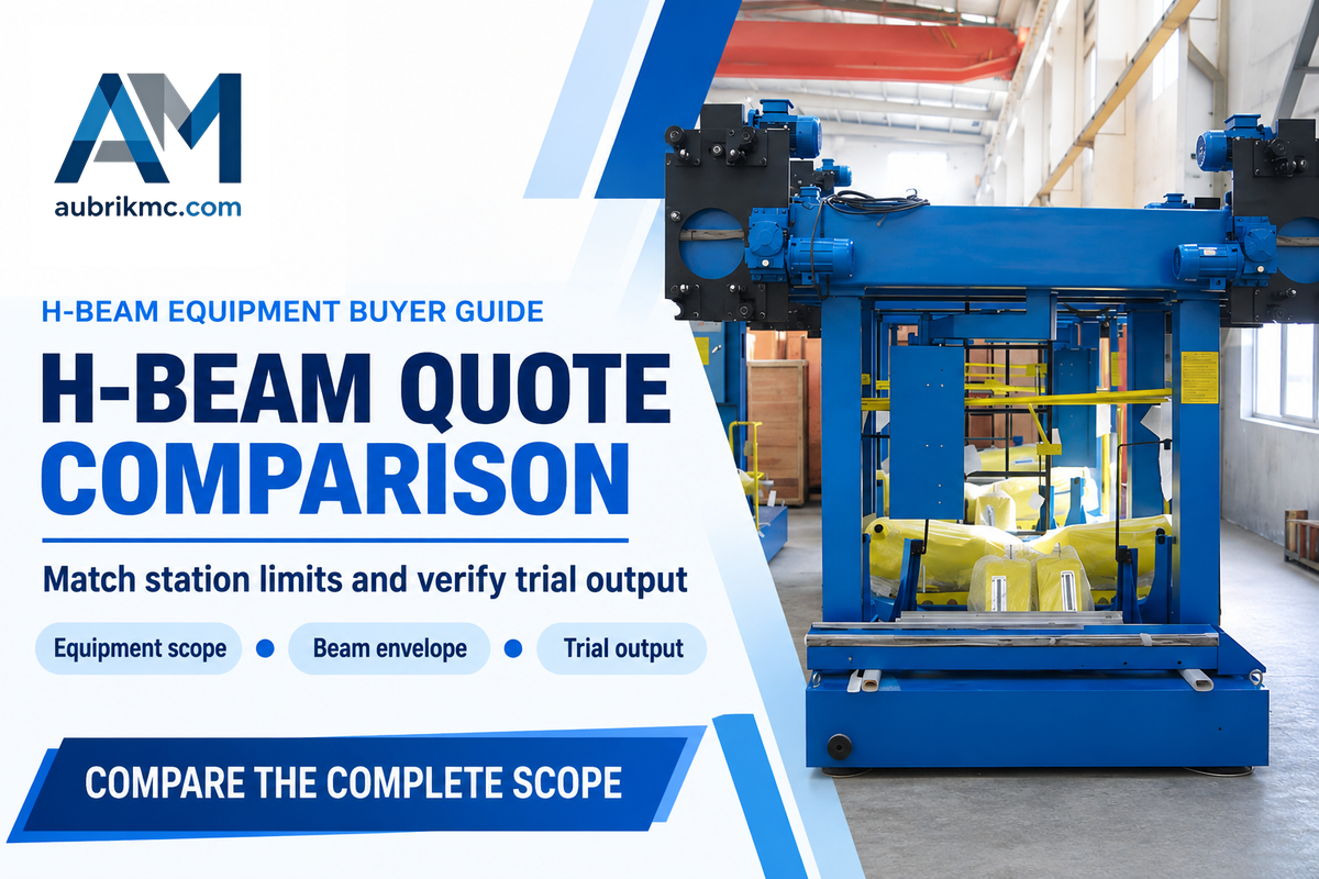
We sell h beam making machine systems for welded steel sections. Use this guide to compare equipment proposals already on your shortlist. Starting with beam drawings and production mix, consider solutions including a retrofit welding station, a 3-in-1 unit and a separate-station line. Analyze the entire process from plate prep to accepted beam, then consider the cost.
Aubrik’s H-beam production line consolidates assembly, welding and downstream equipment into a single purchase discussion. This guide shows how to match station limits, calculate welding time and define a trial that your production, finance and quality teams can all use.
What an H Beam Making Machine Actually Includes
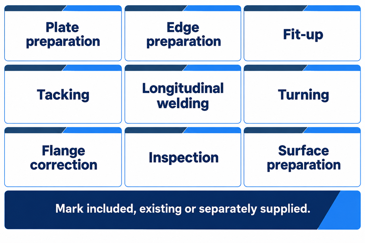
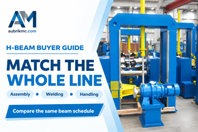
There are five main steps in producing a welded H beam: plate prep, assembly, longitudinal welding, dimensional correction and inspection. Handling connects them. A complete h-beam production line must cover those functions, although one machine may combine several stages and your workshop may already own some of the equipment.
What is an H beam welding machine used for?
An H-beam welding machine connects the web and flanges of an assembled H beam along the specified weld seams. It doesn’t roll a hot billet into a beam. The drawing determines the welding process and joint requirements; the welding equipment must hold and process that assembly consistently.
According to the American Welding Society’s submerged arc welding guide, power source and wire feed, and the equipment for welding flux delivery and travel are the key elements behind the process. For long seams on beam welding lines, these are separate purchasing items even when the seller calls the package an automatic welding machine.
| Operation | Equipment or interface | Buyer’s scope decision |
|---|---|---|
| Plate preparation | CNC cutting machines and edge preparation | Confirm plate size, cut quality and material grade. |
| Edge preparation | Edge milling machine where the joint requires it | Do not buy milling solely because it appears in a line diagram. |
| Fit-up | H beam assembling machine | Match both web and flange dimensions. |
| Tacking | Assembly welding arrangement | Identify who provides the approved tacking procedure. |
| Longitudinal welding | Gantry type or cantilever welding machine | Specify seam access and simultaneous welding heads. |
| Turning | Turnover device and transfer equipment | Assign capacity, supports and operator responsibility. |
| Flange correction | H beam straightening machine | Match flange thickness together with steel grade. |
| Inspection | Measurement and weld examination | State the contract acceptance requirements. |
| Surface preparation | Shot blasting machine when required | Separate surface preparation from weld acceptance. |
CNC cutting can use flame, plasma cutting or laser cutting equipment suited to the plate and joint preparation. A cutting machine selected for thin sheet may leave heavy steel plate work outside its useful range. Keep that selection connected to the incoming plate schedule, rather than the maximum finished beam alone.
3-in-1 or Separate H Beam Welding Machines?
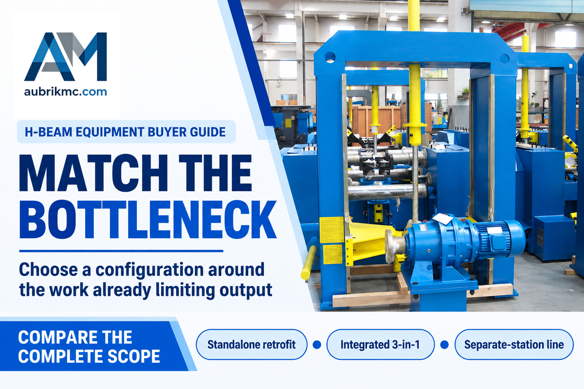
There are three practical setups that cover the vast majority of buying configurations. These include adding a welding station to the existing setup, combining assembly and correction in an integrated unit, or separating the functions across a line. Ensure the setup addresses the work that already limits output in your H-beam fabrication workshop, and check that it accommodates the largest and smallest planned sections.
| Configuration | Useful starting situation | Constraint to resolve |
|---|---|---|
| Standalone retrofit | Plate preparation and fit-up already work well | Existing handling must feed the added welding station. |
| Integrated 3-in-1 | Repeated sections can share one assembly, welding and correction route | All combined functions must accept the same section and grade. |
| Separate-station line | Different operations need independent scheduling | Transfers, buffers and floor space become part of the capacity plan. |
An integrated h beam assembly welding arrangement reduces transfers between its combined welding and straightening operations. Separated functions allow an assembly machine to prepare the next workpiece while welding continues elsewhere, if there’s sufficient buffer and workpiece handling to support the overlap. Compare productivity and high efficiency with the accepted output of the work mix.
Assume there’s a workshop that already has a usable fit-up bed and plate cutting capacity. In this purchasing scenario, its queue forms at longitudinal welding, while plate preparation waits for the welding bay to clear. The goal is to improve welding efficiency. A standalone gantry welding machine deserves a try before the owner swaps the entire route. By contrast, if repeated re-clamping and crane transfers consume the shift, integration may address the actual loss. A financial assessment should include retained equipment, change in handling, and the disruption during installation. Buying a complete line to get rid of one welding queue can result in useful equipment remaining idle and not solve the transfer problem.
Aubrik’s H-beam line configuration selector can be a help for the layout discussion. Sean Moran’s 2011 article on subarc for structurals explains various systems and their relationship with different beam orientations. Descriptions of H-beam welding lines remain relevant; historic performance examples shouldn’t be taken as a forecast for a new installation.
Match Web Height, Flange and Beam Length
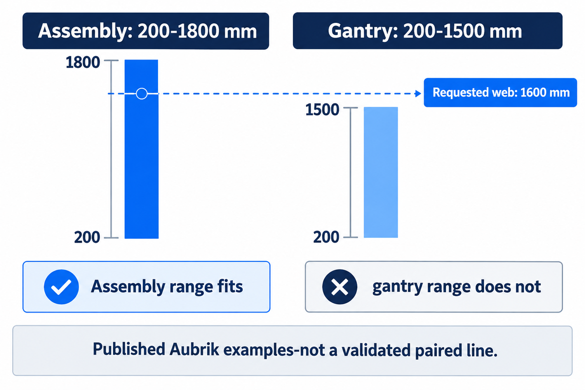
Aubrik has 200-1800 mm web height for the AUB-HB2000 assembly machine, and for the AM-HG4000 gantry it’s 200-1500 mm. As such, a pairing requires a match on a station-by-station basis; an assembly station that accepts a beam section doesn’t make the downstream welding station suitable for that beam.
| Published parameter | AUB-HB2000 assembly | AM-HG4000 gantry welding |
|---|---|---|
| Web height | 200–1800 mm | 200–1500 mm |
| Flange width | 200–800 mm | 200–800 mm |
| Beam length | 4000–15000 mm | 2000–12000 mm |
| Movement rate | 0.5–5.5 m/min assembly feed | 300–600 mm/min welding travel |
These values are from the H-beam assembly machine specifications and gantry welding specifications. Feed speed and welding travel describe different operations. Maximum height, thickness and length also require confirmation as a combined workpiece, with its weight and steel grade included.
Consider a quotation for a 1600 mm web and a 12 m beam. The assembly height falls within the smaller assembly model’s published range, but is greater than the gantry example’s 1500 mm limit. A larger gantry or another documented configuration is needed before price comparison makes sense. Reducing the web height on a supplier’s demonstration piece would hide the mismatch. Keep the original drawing in the trial request, to include flange thickness, web thickness and any taper, so that the seller provides an example of the correct section family. The quality team should document the measured finished geometry and the settings of the equipment that produced it.
For heavy duty h beam work, straightening capacity must be stated for the relevant material strength as well as thickness. Carbon steel is a broad description, not a grade-specific correction limit. Use the H-beam capacity and standards checker to draft your questions, and retain the approved drawing and supplier’s associated equipment schedule in the order.
Turn Welding Speed into a Beam-Time Estimate
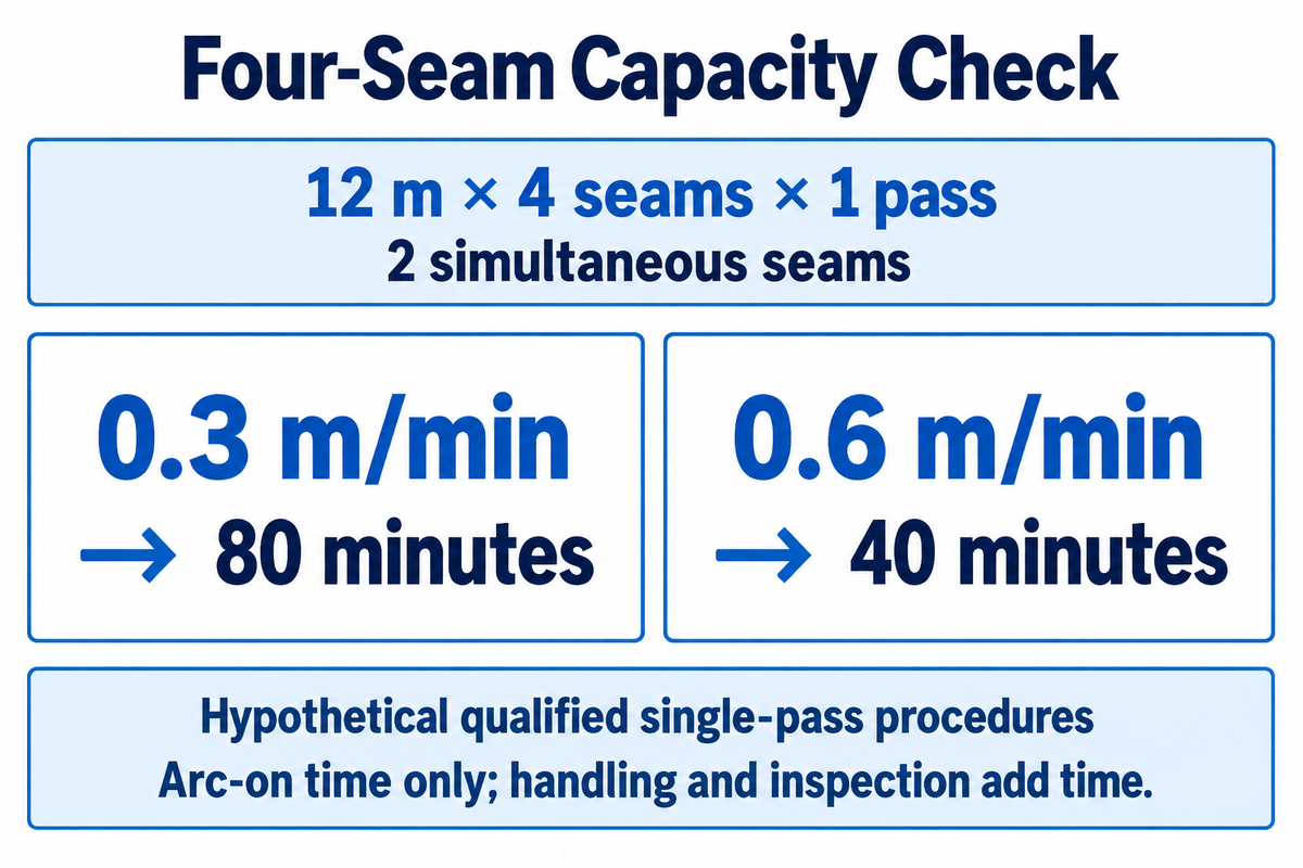
For a 12 meter beam with four longitudinal seams, two heads welding different seams simultaneously and one pass per seam, calculated arc-on elapsed time is 80 minutes at 0.3 m/min or 40 minutes at 0.6 m/min. Each speed must first have its own qualified procedure meeting the same drawing requirements.
This is called the Four-Seam Capacity Check. Inputs include length of beam, number of seams, and number of passes and independently operating heads. The example assumes equal-length continuous passes. Two welding wires feeding the same seam don’t constitute two simultaneously completed seams.
Four-Seam Capacity Check
Arc-on elapsed time = beam length × seam count × passes per seam ÷ (simultaneously welded seams × travel speed).
At 0.3 m/min: 12 × 4 × 1 ÷ (2 × 0.3) = 80 minutes.
At 0.6 m/min: 12 × 4 × 1 ÷ (2 × 0.6) = 40 minutes.
The inputs describe hypothetical qualified single-pass procedures. They don’t establish that either speed will make the required weld on your beam.
The published gantry range of 300–600 mm/min converts to 0.3–0.6 m/min. Welding speed alone can’t establish weld size or quality: the process also involves current, voltage, wire feed and consumables, as the AWS guide explains. Additional passes increase required arc time, and other factors such as loading, turning, cleaning, and inspections add time.
Meyer and Koltz describe the distinction of arc-on time deposition and labor-hour production in their 2023 welding production explanation. Because of this, an automatic h beam welding line should be evaluated with time stamps, and not just welding speed.
| Stage | Measurement to record | Decision the result supports |
|---|---|---|
| Plate cutting | Ready plates per scheduled hour | Whether CNC cutting can supply the welding line. |
| Plate staging | Waiting minutes before fit-up | Whether crane availability limits feeding. |
| Assembly | Start-to-tack-complete minutes | Whether fit-up becomes the next queue. |
| Flux and wire setup | Preparation minutes per change | Whether short batches lose usable welding time. |
| First welding orientation | Qualified arc-on minutes | Whether the procedure matches the calculated route. |
| Turnover | Last arc-off to next ready position | Whether handling erases a faster welding pass. |
| Remaining seams | Pass count and arc-on minutes | Whether all four seams were included. |
| Correction | Straightening and recheck minutes | Whether correction limits accepted output. |
| Release | Accepted beams per scheduled shift | Whether production efficiency survives inspection and rework. |
How many operators are necessary to work on CNC plate cutting, H Beam assembly, SAW welding, and straightening?
Staffing should follow simultaneous tasks and safe coverage, rather than one operator count for every line. Map who loads, controls welding, turns beams, checks dimensions and handles consumables during the timed trial. If two tasks require the same crane operator at once, add waiting time or change the staffing plan. The labor and throughput estimator is a starting worksheet; a production trial supplies the actual inputs.
Compare H Beam Production Line Quotes
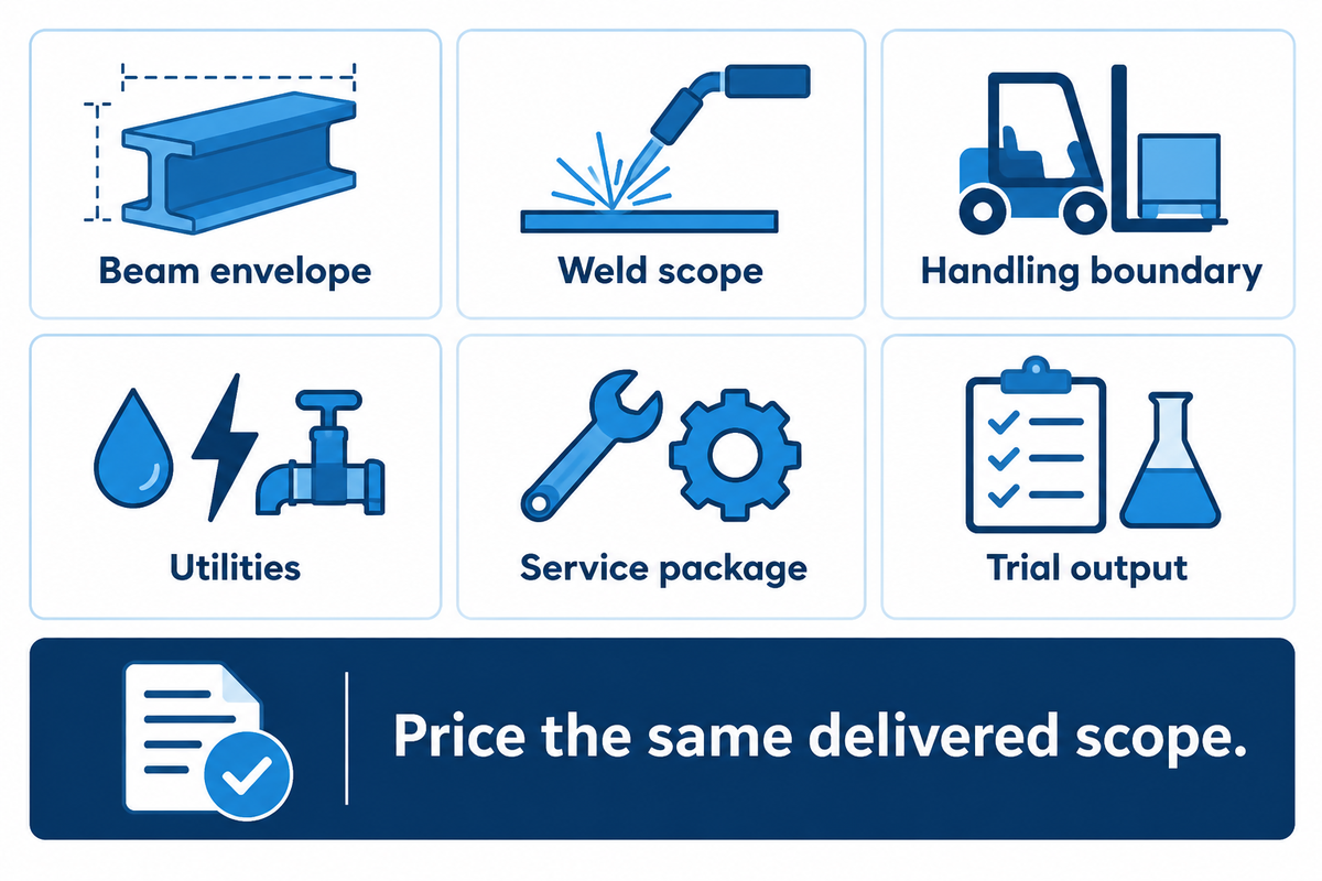
When quoting against an acceptance plan and a firm equipment boundary, consider that a low welding price can include the carriage, while another quote covers the power source and installation. Procurement should price the same delivered scope before finance compares payback or the plant manager compares promised output. For steel structure manufacturers, accepted output is the useful comparison.
Separate welding power supplies from gantry drives. List flux recovery equipment, conveyors, turnover equipment, straightening rollers, spare consumables, freight and commissioning separately. If the customer requires a prepared surface, include the selected shot-blasting equipment and its extraction as a finishing package.
| Parameter | Recommended range / entry | Why it matters | How to verify |
|---|---|---|---|
| Beam envelope | Minimum, typical and maximum drawings | Exposes mismatched stations | Attach dimensions, grade and mass. |
| Weld scope | Drawing weld sizes and pass plan | Controls time and acceptance | Review qualified procedure and trial. |
| Handling boundary | Loading through released beam | Makes offers comparable | Mark supplier and buyer responsibilities. |
| Utilities | Complete connected-load schedule | Avoids installation omissions | Separate drives, welding and auxiliaries. |
| Service package | Named spares and response terms | Makes downtime planning concrete | Obtain part numbers and written scope. |
| Trial output | Accepted beams and recorded cycle | Connects price to useful capacity | Time the agreed representative work mix. |
For a finance comparison, divide the quoted equipment premium by the verified monthly net saving to estimate simple payback. Premium varies by specification; request a matched quotation. Include additional effects of maintenance, financing and changeover before considering the net saving achievable. An offer with a faster welding head but unchanged accepted output contributes no capacity benefit to that calculation.
Check Weld Quality and Straightening Before Shipment
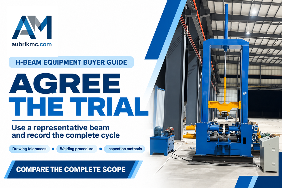
An efficient factory trial produces the required weld and finished geometry on a representative beam and captures the complete operating cycle. Establish agreement on the trial items, including drawing tolerances, welding procedure, inspection methods and correction responsibilities, prior to the factory trial. The quality team needs those acceptance conditions as much as procurement needs the equipment list.
The American Institute of Steel Construction’s inspection guidance notes that visual inspection is only one of many methods of examination. Select examination requirements from the project specification and applicable code; do not impose one universal testing percentage on every weld or treat a machine’s tracking accuracy as a finished-beam tolerance.
Prior to the first arc, careful attention should be paid to fit-up. As TWI states, insufficient tacking can allow a joint to open during submerged arc welding. TWI’s guidance to prevent distortion explains the reasoning behind weld balance and restraint. A straightening machine corrects specified geometrical defects; it doesn’t replace control of weld size and sequence.
“The tack welding sequence is important to maintain a uniform root gap along the length of the joint.”
During a trial, document starting plate condition, assembly measurements, welding parameters and correction settings. Be sure to document inspection results and record rework time. Poor reworking can damage a component, according to TWI’s guidance on distortion correction. For h beam straightening, agree the correction method and reinspection sequence with the responsible fabrication team.
Choose a Supplier and Plan Maintenance
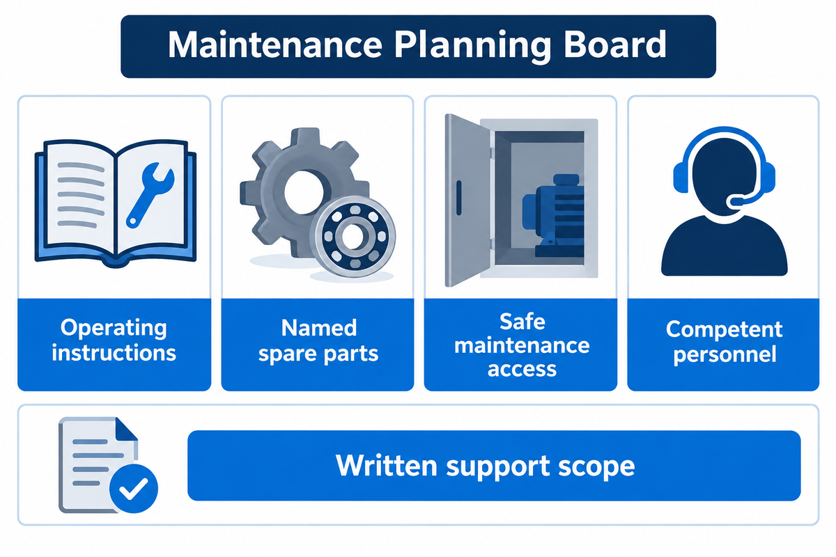
A relevant supplier must demonstrate your section family and supply a service package that includes operating instructions, identification of components, maintenance access and support. A clean demonstration beam answers a quality question. Keeping the same equipment productive after wear, a fault or a controller replacement requires a different set of commitments.
When comparing Wuxi suppliers such as Aubrik and Zhouxiang, keep the same drawing and scope in each enquiry. Our comparison of H-beam production line manufacturers helps compile a shortlist. The final choice depends on the machines and the support conditions offered for your workshop.
For SAW welding machines, identify wear parts related to wire feeding, contact tips, flux management and guidance. For correction equipment, identify the straightening roller arrangement and the replacement procedure. Ask which parts are available locally, which require the original supplier, and what information is necessary to order the correct version.
The UK HSE maintenance guidance highlights the importance of competent personnel and safe access. UK guidance permits the use of in-house maintenance staff and recognizes the need for specialist support for more complicated equipment. Learn from that experience and assess access and training prior to acceptance of an item of plant. Keep maintenance frequencies tied to the equipment manual and operating conditions, rather than accepting an unsupported universal lifespan.
Industry Outlook: 2026 Installation and Acceptance Planning
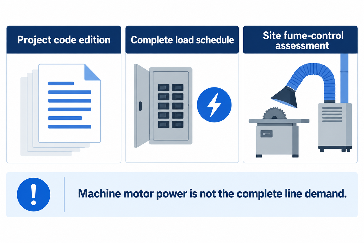
For 2026 procurement, include in the request for quotation the project’s edition of the welding-code, along with the installation plan for the workshop. AWS lists D1.1/D1.1M:2025-AMD1, with public highlights of the qualification and inspection changes. Where the project specifies that edition, the procedure and acceptance documentation should match it from the start.
AWS’s D1.1 publication page provides the edition reference. Resolving the required edition with the project team aligns the acceptance basis for competing suppliers. The practical purchasing change is documentation alignment, not a claim that every new machine is certified to the code.
The initial stage of workshop integration is to develop a reference layout to identify beam entry and turning, crane movement and access/discharge. Keep steel moving through that route without blocking service access. Obtain a load schedule for drives and welding sources and auxiliaries. For the procurement of a machine for steel structure production, a gantry’s installed motor power shouldn’t be used as the electrical demand of a complete steel structure production line. State the supply constraints in the electrical network, including voltage and frequency, in the procurement request, to allow the Electrical Design to be developed based on the site conditions.
Include welding-fume control in that layout. UK HSE guidance on welding controls considers the process, workload, component size, material and consumables, and addresses people around automated welding equipment. Have the destination site assessment determine extraction and ventilation systems. Flux covering the arc does not remove the need to consider nearby workers or associated fabrication tasks.
Similarly, new welding technology requires a defined process boundary. A welding robot or laser welding proposal should come with its own access, joint and qualification demonstration; it is not automatically interchangeable with a submerged-arc gantry. The same goes for a welding manipulator and welding positioner intended for another workpiece family. A process study is required to evaluate its impact on an H-beam route. We discuss where to include automation in our welding automation planning guide.
Frequently Asked Questions
Can WUXI ABK MACHINERY provide custom H-beam production line solutions?
Aubrik offers H-beam production line configurations around the required beam mix and workshop layout.
Start the discussion with dimensioned drawings, steel grades and target production. Our published assembly and gantry ranges provide an initial equipment shortlist. A matched proposal should identify the selected models, handling arrangement and optional finishing equipment. Keep any custom section, taper or unusual joint detail in the drawing package so the quotation and acceptance trial address the same work.
Does the machine include automatic seam tracking?
Tracking equipment depends on the selected welding model and the quoted configuration.
Aubrik’s gantry welding product page describes seam-tracking functions. Ask for the proposed arrangement to be demonstrated on your actual joint, including normal fit-up variation and access along the beam. Record how the system follows the seam and handles starts or interruptions. Tracking performance, weld acceptance and finished dimensional tolerance remain separate checks in the trial record.
What is the typical lifespan and maintenance requirement for H-beam production equipment?
Use the equipment manual and operating history to plan maintenance; there is no single reliable lifespan for every line.
Duty, loading, environment, component selection and maintenance affect service life. Set up inspection and replacement tasks for the supplied equipment, keep fault and service records, and identify parts that can stop production while replacements arrive. Training should cover safe isolation and reporting of damaged equipment. A written spare-parts and support plan is more useful for ownership planning than an unqualified lifetime promise.
Can an H-beam making machine also produce tapered beams?
Tapered beams require a configuration that accepts the changing geometry.
Specify the taper, end dimensions, length and joint access before selecting the machine. Likewise, box beam production needs its own assembly and welding route; open H-beam equipment shouldn’t be assumed to provide a complete box beam production line.
What should I send with my first quotation request?
Send drawings, material grades, weld requirements, production mix, site utilities and the required delivery scope.
Include minimum, typical and maximum sections with web height, flange width, both plate thicknesses and beam length. Add workpiece mass, taper or camber details and the drawing weld sizes. Explain which operations your workshop already owns and where the current queue occurs. For a new workshop, identify the available floor area and planned handling equipment. State scheduled shifts and accepted output targets without converting them into an assumed welding speed. Attach the required inspection criteria and applicable project code edition. List power supply, ventilation interfaces, destination and installation responsibilities. Ask the supplier to return a matched station schedule, exclusions, spare-parts package and a representative trial plan. That response gives purchasing, production and quality staff the same scope to review before the order is placed.
Plan your H-beam line
Send beam drawings and workshop constraints through our H-beam equipment enquiry page. Aubrik can use them to examine a suitable h beam welding machine and the line equipment. Keep the drawing, quotation and timed trial together as the project moves from selection to purchase.
Related Articles
- H-beam production line planning guide
- H-beam assembly machine ranges
- Gantry welding machine configurations
- H-beam equipment manufacturers
References and Sources
- American Welding Society: A Practical Guide to Submerged Arc Welding, July 2025.
- American Institute of Steel Construction: Welding Inspection and Non-Destructive Examination.
- TWI: Distortion Control: Prevention by Fabrication Techniques.
- David Meyer and Robert Koltz: Deposition Rate, Deposition Efficiency and Production Output, 2023.
- Health and Safety Executive: Maintenance of Work Equipment.
Prepared by Aubrik from its published equipment specifications and the named technical sources, checked in October 2026. Worked production and finance examples use stated assumptions; they aren’t customer test results.