Get in Touch with Aubrik Company

Updated June 2026.
Self-aligning welding rotators are turning rolls whose wheels pivot to fit each workpiece on their own, so a fabricator can rotate a 600 mm pipe and a 4 metre tank on the same bed without sliding a single roller by hand. That one trait, the wheels finding the part instead of an operator setting them, is what separates a self-aligning rotator from a conventional one, and it changes how a shop welds long circumferential seams. This guide explains how the mechanism actually work, how the four roller types differ at the level of the hardware, how to read load and diameter limits, how to diagnose the faults that show up on the shop floor, and which certificates actually prove anything. It’s the engineering background; when you’re ready to size and price a unit, our self-aligning turning rolls from 5 to 500 tonnes carry the spec tables.
Quick Specs: Self-Aligning Welding Rotator
| Capacity classes | 5–500 t per set (custom above) |
| Workpiece diameter | ~250–6,300 mm across the model range |
| Line speed | 6–60 m/h, stepless VFD control |
| Wheel material | Polyurethane (PU) or steel-faced |
| Set layout | One drive unit + one or more idler units |
| Manual setup per diameter | None — wheels self-center on load |
| Typical process | SAW, GMAW (MIG/MAG), GTAW (TIG) |
What a Self-Aligning Welding Rotator Actually Is (and Where “Turning Roll” Fits)
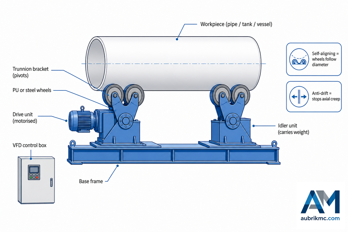
A self-aligning welding rotator follows the workpiece diameter with pivoting wheels, but it does not automatically solve axial drift. Specify diameter range, loaded weight, vessel length, anti-drift control and roller contact together when the seam must stay on track. Confirm how the control responds to taper, changing load distribution and a stop-start weld cycle.
This self-centering behaviour is documented engineering, not a vendor claim: U.S. Patent 8,342,493 B2 sets out a rotator whose idler wheels balance and centre the load on their own. “Welding rotator,” “turning roll” and “self-centering rotator” all name the same family of machine; the words travel by region and by catalogue, not by function. By application, the same machine show up in catalogues as tank turning rolls, pipe turning rolls or vessel turning rolls; by size, as a small welding rotator for sub-metre pipe or a heavy bed for wind-tower cans. None of those labels changes the mechanism, only the duty the bed is sized for.
One point worth clearing first: the difference between a rotator and a welding positioner. Rotators turn a round, long workpiece on rollers so the torch can lay a continuous circumferential or longitudinal seam. Positioners tilt and turn a part on a table or headstock, which suits brackets, frames and smaller assemblies that need to be tipped to a flat position. If the work is cylindrical and runs metres long, it belongs on a rotator; if it has to be angled, it belongs on a positioner.
One more distinction surprises buyers, and the rest of this guide leans on it: “self-aligning” and “anti-drift” are two separate features, even though catalogues often blur them. Self-aligning describes how the wheels follow a change in diameter. Anti-drift describes how the bed keep a long part from creeping sideways along its own axis as it spins. Any rotator can be self-aligning without being anti-drift, and the better builders sell them as distinct options. Keep the two ideas apart and most of the engineering below fall into place.
Buyers who conflate the two often skip anti-drift on a long, thin-wall job, then struggle with a seam that wanders sideways as the part turn, a mistake that can scrap a finished vessel and cost days of rework. Because the structural reason is geometric rather than a control glitch, no amount of operator skill recovers it after the fact; the only fix is written into the purchase order. Around 1 mm of axial creep per metre is enough to push a root pass outside a 2 mm fit-up window on a 3 m seam, which is why this distinction earns its own paragraph rather than a footnote.
How the Self-Alignment Works: Trunnion Geometry, Step by Step
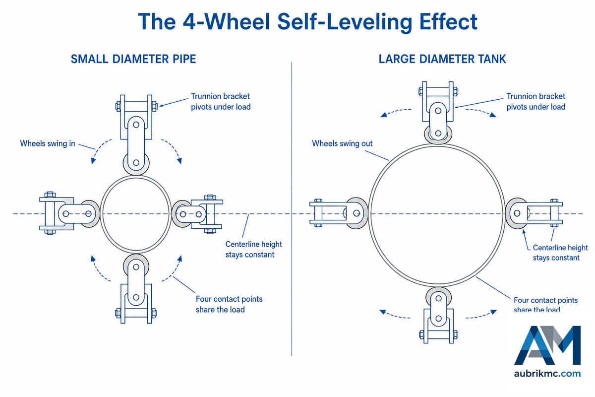
Strip away the catalogue language and a self-aligning rotator does one mechanical thing well. Each wheel set sit on a trunnion bracket, a bracket free to pivot, rather than bolted to a fixed point on the frame. When a vessel is craned onto the bed, its own weight rolls the brackets until the wheels cradle the curve.
Small pipes pull the wheels in close; a wide tank let them swing out. No operator measures anything; the part settles and the geometry follows. Throughout, the bed holds the workpiece during the welding process so the torch can stay in one place while the seam comes to it; mechanising the welding process this way is the whole reason a powered bed beat turning a vessel by crane.
Here’s the chain of events on a single load: the crane lowers the workpiece → the trunnion brackets pivot under load → the wheel pairs rotate inward or outward until four contact points share the shell → the part centres itself → the wheel carriers self-lock once it stops moving. That self-centering action is what we call The 4-Wheel Self-Leveling Effect: a self-aligning unit carries the load on four wheels per power/idler set (two rollers on each pivoting bracket) instead of the two fixed wheels of a conventional bed, so the weight spreads across more contact area and the shell is far less likely to dent. Conventional rotators concentrate the same tonnage on fewer points, fine for thick carbon steel, risky for thin stainless.
📐 Engineering Note
Because the wheels self-center, the workpiece centerline stays at roughly the same height whatever the diameter. Under a fixed welding head or a column-and-boom, the torch height barely changes between a 1 m pipe and a 3 m tank, so operators stop chasing seam position every time the part size change. That constant centerline is the quiet reason self-aligning beds pair so well with automatic welding.
What are the different parts of a self-aligning welding rotator?
Each standard set ship as one motorised drive unit plus one or more freely turning idler units. Inside each you’ll find the trunnion brackets, the PU or steel-faced wheels, an enclosed reducer/gearbox driving the powered wheels, and a variable-frequency (VFD) control box that sets a stepless line speed.
Drive units turn the workpiece; idler units carry weight and keep the part level. Self-locking on the wheel carriers hold the geometry once the part is centred, and on larger beds a drift sensor and controller can be added for axial tracking, which is a different system, covered next. This mechanism is old and well-documented: U.S. Patent 4,407,621 describes self-adjusting carriages that convert a carriage’s axial movement into a swivel of the roller holder. In our own shop we load-test every bed through its full speed range before it ships, because a self-centering action that binds under load is worse than no automation at all. If you want the broader category background first, our guide to how welding rotators work covers the whole turning-roll family.
The Anti-Drift Problem: Why Long Seams Wander and How Angled Idlers Fix It
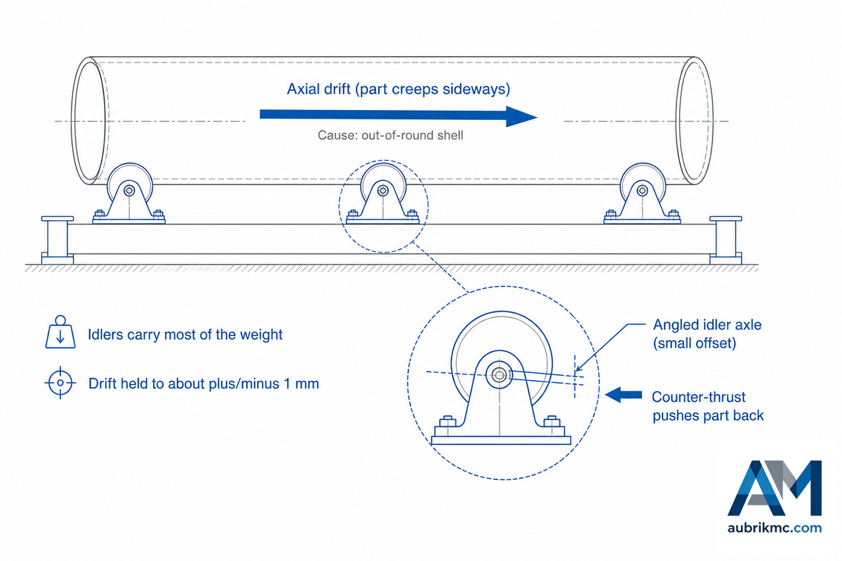
Spin a long cylinder on plain rollers and it rarely turns true. It creeps along its own axis, what the trade calls axial drift or axial creep, and on a metres-long circumferential seam that creep show up as a wandering weld bead. That cause is mechanical, not operator error: the anti-drift turning-roll patent from Koike Aronson states it plainly, that drift come “mainly [from] imperfections in the cylindrical shape of the workpiece.” No shell is perfectly round, so rotation walks the part sideways.
An elegant fix is to tilt the idler wheels a hair. In the design covered by U.S. Patent 8,342,493 B2, each idler roller turn on an axle whose axis sits at a small offset, about one degree, from the bracket’s pivot axis. Pivoting that axle introduces a gentle axially-directed force that pushes the part back toward its reference position. On the powered version, a drift sensor reads the part’s axial position and a controller commands the idler axles, holding drift inside about ±1 mm, provided the drive and idler rollers stay aligned within roughly 1 mm/m of their separation and the shell is round within about 1 mm/m of its diameter, the tolerances the patent set out. The idler axles can swing up to ±45° from neutral, far more than the roughly 0.3° of initial misalignment a real shell presents, so most of that range stays in reserve. That same patent notes a setup detail most operators never see: it recommends carrying roughly 60% of the workpiece weight on the idler rollers and about 40% on the drive rollers, because the anti-drift correction loses authority as weight shifts off the idlers.
⚠️ Common misconception
Many buyers assume any roller bed tracks straight on its own. It doesn’t. Plain self-aligning beds adapt to diameter but do nothing about axial creep on an out-of-round shell. Anti-drift is a separate, added system, the angled idler axles plus, on automatic lines, a sensor and controller. If your seams are short, you may never need it; if you run long submerged-arc circumferential welds on real-world (slightly oval) cans, ask whether the bed is self-aligning and anti-drift, not just one of the two.
Self-Aligning vs Conventional vs Adjustable vs Fit-Up: A Mechanism-First Comparison
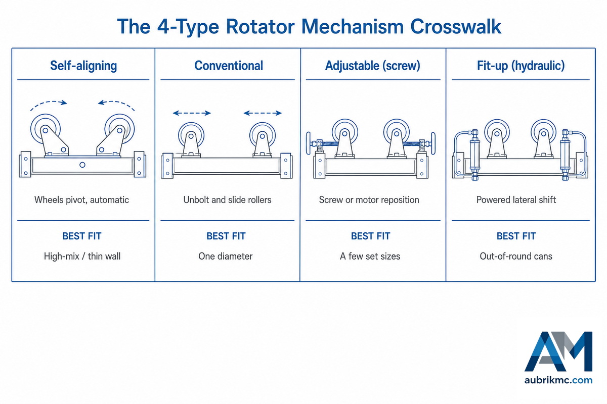
Four roller-bed types share the same job and differ in exactly one thing: how the wheels follow a change in diameter. Sales sheets sort them by price; it’s more useful to sort them by mechanism, because the mechanism is what drives the price, the setup time and the risk to a thin shell. Read each type against the traits that actually matter on the floor, as the crosswalk below does. Shops that use self-aligning rotators report far less re-setup time compared to manual welding and compared to conventional rotators, because the self-aligning mechanism, the self-adjusting carriage of U.S. Patent 4,407,621centres each part on its own; conventional welding rotators would otherwise tie up an operator at every diameter change, and self-aligning rotators are also the easier partner for a robot cell.
4-Type Rotator Mechanism Crosswalk
| Mechanism trait | Self-aligning | Conventional | Adjustable (screw) | Fit-up (hydraulic) |
|---|---|---|---|---|
| Diameter changeover | Automatic, seconds | Unbolt + slide rollers | Screw or motor reposition | Powered lateral shift |
| Manual setup per diameter | None | Yes, every change | Partial | Powered, not manual |
| Wheels per power/idler unit | 4 (2 per pivot bracket) | 2 fixed | 2–4 | 2–4 powered |
| One-setup diameter coverage | Full rated range | One band | Stepped range | Rated range |
| Thin-wall contact pattern | 4-point, low point load | 2-point, higher point load | 2–4 point | 4-point |
| Extreme diameter reach | Limited by arm swing | Widest (rollers move far) | Wide | Limited by arm swing |
| Out-of-round fit-up | No | No | No | Yes — brings cans concentric |
| Mechanical complexity | Higher (pivots) | Lowest | Medium | Highest (hydraulics) |
| Best-fit job | High-mix diameters, thin wall, fixed head | One diameter, high volume | A few set diameters | Large cans needing concentric tack |
Mechanism behaviour synthesised from turning-roll patent literature and field practice; capacity figures vary by model.
What are the different kinds of welding rotators?
In practice you meet four. Conventional (sometimes called manual) rotators bolt the wheels to the frame; you unbolt and slide them for each new diameter, and in exchange you get the simplest, most durable design and the widest diameter reach, the rollers can move very far apart or close together.
Adjustable or lead-screw rotators reposition the wheels by screw or motor, a halfway house for a few set sizes. Self-aligning rotators let the wheels pivot to the part with no setup. Fit-up rotators add powered hydraulics that also raise, lower and shift the wheel sets so two shell sections can be brought concentric and tacked before the seam run. Read it honestly: self-aligning rotators offer real value where the diameter mix change often or the wall is thin, but a single-diameter line is frequently better served by a conventional bed, cheaper, with nothing to calibrate. That decision is a buying one, and the spec tables live on our self-aligning welding rotator page.
Load and Diameter: The Eccentric-Load Principle Most Buyers Miss

One number get sizing wrong more than any other: the headline tonnage. Rated capacity holds only when the load sit centred on the rollers. Push the centre of gravity off-centre, an off-axis nozzle, an uneven head, a fixture hung on one end, and the usable capacity drop fast. Rated for 100 tons, safe for well under 60 isn’t a typo; it’s what eccentricity does to a roller bed. An industry sizing guide shows the pattern in small numbers: a 1,000 kg-rated unit may carry only about 600 kg once the load sits 200 mm off-centre, roughly a 40% loss.
Physically, it’s the tilt torque the offset create. As positioner-sizing references put it, you take the weldment weight and multiply by the distance from the roller centreline to the centre of gravity; that moment, not the bare weight, is what the bed has to hold, the same idler-and-drive load split set out in U.S. Patent 8,342,493 B2. So the right way to size is to start from the heaviest workpiece plus its fixture, multiply by a 1.5× safety factor, and read that against the eccentric (off-centre) rating rather than the headline figure. Four numbers decide whether a rotator perform in your shop: heaviest weight, eccentric distance, smallest and largest diameter.
“The failure we see in the field is never the headline tonnage, it is an off-centre vessel on an under-sized carrier. We check the wheel carriers under eccentric load before a bed ships, because that is where an honest spec sheet earns its keep.”
Aubrik Engineering Team, Wuxi ABK Machinery
Diameter range works the same way: the published band (roughly 250–6,300 mm across a model range) is the envelope of the whole catalogue, not one bed. Each set cover a slice of it, set by its capacity class. To put real numbers against your own work, our tools to size a self-aligning welding rotator apply the eccentric derating for you.
Polyurethane vs Steel Wheels: Matching the Wheel to the Shell
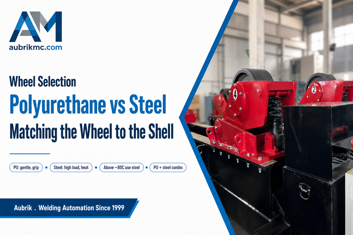
Wheel material is a quieter decision than capacity, and it changes the surface finish you live with. It comes down to wall thickness, the temperature near the weld, and the load. How that load reaches the shell depend on the roller-holder hardware itself; U.S. Patent 4,407,621 details the self-adjusting carriage and roller holder that carry whichever wheel face you fit.
✔ Polyurethane (PU) wheels
- Gentler on the shell; protect thin-wall and finished surfaces from indentation
- Better grip, so less slip on a lightly unbalanced load
- Damp noise and vibration
- Wear faster, the tyres are a replaceable consumable
⚠ Steel-faced wheels
- Carry higher loads per wheel
- Tolerate the elevated temperature near a heavy weld zone, above roughly 80 °C, where PU would soften
- Longer service life under abrasive conditions
- Less forgiving on thin or polished shells, higher point load, scuff risk
One mistake worth naming is fitting steel everywhere because it “lasts longer.” On thin stainless or aluminium, a hard wheel concentrates load and can leave an indentation or a scuff that turn into extra polishing, or a rejected vessel. Many pressure-vessel shops run a PU/steel combination: PU on the idlers that cradle the shell, steel where the heat and load are highest. Selection follows the workpiece, not a blanket preference.
Where Self-Aligning Rotators Earn Their Keep (and Rotator vs Positioner)
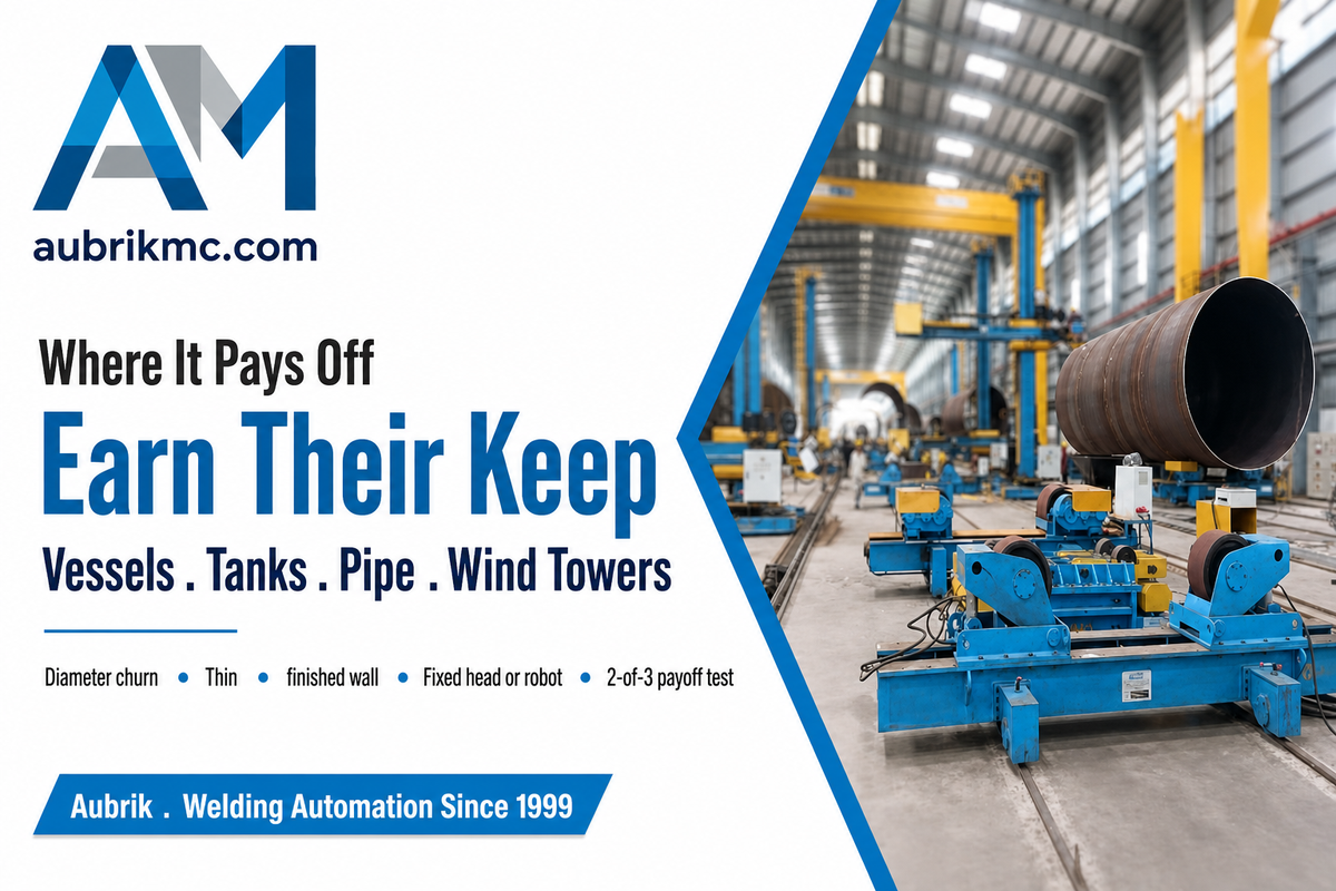
Self-aligning beds turn up wherever a shop welds large cylinders in a changing size mix: pressure vessels and storage tanks, pipe spools, heat exchangers, wind-tower sections, and shipbuilding panels rolled into cans. One case makes the value obvious: a mixed week, a 20-ton stainless tank one shift, a 60-ton carbon vessel the next.
On a conventional bed every change means stopping to unbolt and reposition rollers; on a self-aligning bed the next part simply settles in. Both of those vessels, if they hold pressure, are built to ASME BPVC Section VIII rules for pressure-vessel construction, which govern the welding, inspection and certification of vessels above 15 psig, the kind of uniform seam a rotator is built to lay. Pair that constant centerline with a column-and-boom and a seam tracker and the line run without an operator resetting anything between jobs. Across the types of welding rotators a fabricator might buy, the self-alignment logic is identical. Light welding devices handle small welding jobs; heavier beds run hardened welding rollers for large-scale welding; and the duty itself ranges from hand-guided seam welding to fully automated welding under a boom.
The Self-Alignment Payoff Test — three signals
Self-alignment costs more than a conventional bed. It pays for itself when at least two of these three signals are true:
- Diameter churn. You change workpiece diameters often, several different cans or pipes in a week, not the same size all month.
- Thin or finished wall. You run thin-wall stainless, aluminium, or polished shells where a 4-point cradle prevents the denting a 2-point set risks.
- Fixed head or automation. You feed a fixed welding head, column-and-boom, or seam tracker that benefits from a centerline that doesn’t move between sizes.
Fewer than two true? A conventional rotator usually gives better value, repeatable accuracy at the lowest price, with nothing to calibrate.
How is a welding rotator different from a welding positioner?
Rotators and positioners solve two different geometry problems on the shop floor. Welding rotators (turning rolls) rotate a cylindrical workpiece on rollers, which is what you want for a long, round part, a pipe, a tank, a vessel, welded along a circumferential or longitudinal seam.
Welding positioners tilt and turn a part on a table or headstock, which suits a bracket, a frame, or an irregular assembly that has to be tipped so the weld sit flat. Round and long goes on a rotator; tip-and-rotate goes on a positioner. Many shops own both and hand the part to whichever matches its shape. If your work leans the other way, our notes on the rotary welding positioner and the welding turntable selection guide cover the table-type machines, and the full welding rotators and turning rolls range shows where each fits. For heavier tilting work, the heavy-duty welding positioner notes go further.
Field Failure Modes: Diagnosing Drift, Slip, Indentation and Overload
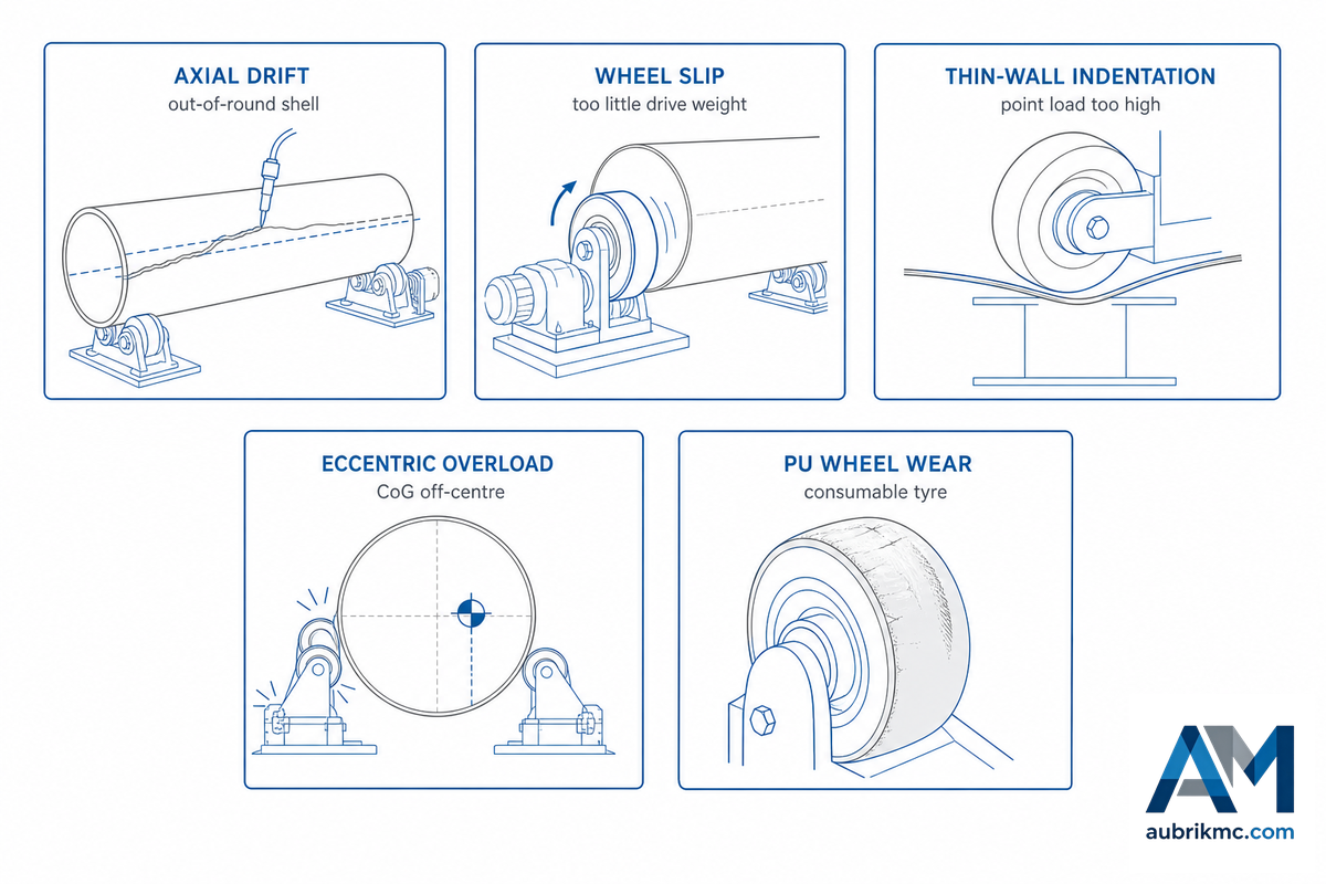
When a self-aligning bed misbehaves, the symptom usually points straight at the cause once you know the five modes. This is the part no sales sheet prints, so it’s the part worth keeping by the machine. Use the atlas below as a first-pass diagnosis, then confirm against the maintenance check underneath.
5-Mode Rotator Failure Atlas
| Failure mode | Symptom on the floor | Root cause | Field fix |
|---|---|---|---|
| Axial drift | Bead wanders sideways along a long circumferential seam | Out-of-round shell; no anti-drift; idlers carrying too little weight | Add/enable angled-idler anti-drift; shift toward ~60% weight on idlers; check drift sensor |
| Wheel slip | Workpiece stalls or jerks; drive turns, part does not | Too little weight on drive wheels; worn or oily PU; off-centre load | Rebalance drive/idler split; clean or replace tyres; re-centre load |
| Thin-wall indentation | Dents or flats on a thin or polished shell | Steel wheels or 2-point bed under a thin wall; point load too high | Switch to PU wheels; move to a 4-point self-aligning set; spread the load |
| Eccentric overload | Carrier strain, motor labour, or trip on a load below the headline rating | Centre of gravity off-centre; sized on bare weight, not the moment | Re-size on eccentric rating × 1.5 safety factor; reposition fixture |
| Wheel/PU wear | Rising slip, noise, or out-of-round running over time | Polyurethane tyres are a consumable; abrasive or hot service accelerates wear | Inspect and replace tyres on a schedule; check pivots and gearbox oil |
| Centerline rise on size change | Torch height creeps as diameter changes | Worn or mismatched wheels; bent trunnion bracket | Replace wheels in matched sets; check bracket geometry within 1 mm/m |
| Surface scuff or marking | Witness marks on a polished or thin shell | Steel wheels on a finished surface; grit on the tyre | Switch idlers to PU; keep wheels clean |
| Drive overheating | Gearbox or motor runs hot, trips on a long run | Oversized load, low oil, or a seized idler adding drag | Re-size to eccentric rating; service gearbox; free the idler |
| Nip-point exposure | Hand or sleeve caught near a rotating wheel | Unguarded rotating parts and ingoing nip points | Fit guards and barriers per OSHA 1910.212; lock out for setup |
- ✔ Keep wheels and trunnion pivots clean; grease pivots on schedule.
- ✔ Check gearbox oil and the wheel-carrier self-locking before a heavy run.
- ✔ Replace polyurethane tyres as they wear, they’re the part most likely to fail first.
- ✔ Guard the rotating wheels and the ingoing nip points: under U.S. machine-guarding rules in OSHA 29 CFR 1910.212, rotating parts that can contact an operator must be guarded.
Parts that actually fail in the field are the drive wheels and the chucks, so those are the wear parts we keep on the shelf. Beds get burned by their controls and their spares pipeline long before they get burned by their steel.
Verifying Quality: The Standards That Actually Govern a Rotator
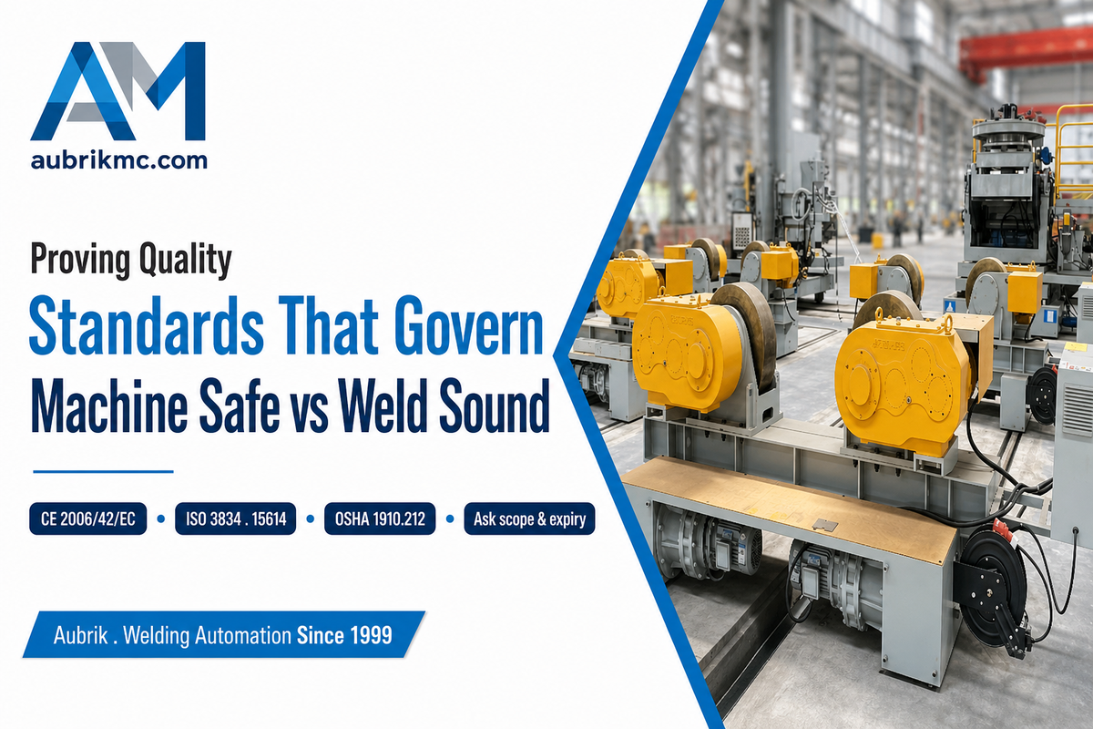
Two different kinds of standard apply to a welding rotator, and buyers conflate them at their cost. One set proves the machine is safe. Another set proves the weld is sound. Logos on a homepage prove neither; ask for the certificate’s scope and expiry.
Get this wrong and the risk is concrete. Any shop that accepts an ISO 9001 logo as proof of weld quality can take delivery of a bed whose welds were never formally qualified, then fail a customer audit months later when a third-party inspector asks for procedure records that were never written. EU and US buyers run exactly this customer audit, and the gap usually surfaces only after a 6 mm-wall vessel is already in service, the most expensive moment to find it.
Machine safety. For the equipment itself, the rotating wheels, the drive, the nip points, the European route is the CE mark under the Machinery Directive 2006/42/EC, which sets essential health-and-safety requirements and a Declaration of Conformity. Note the date: 2006/42/EC is being replaced by Regulation (EU) 2023/1230, the new Machinery Regulation, which applies from 14 January 2027, so a 2026 purchase straddles both, and it’s fair to ask a supplier how they’re handling the transition. In the United States, the parallel duty is machine guarding under OSHA 1910.212: rotating parts exposed to contact must be guarded.
Weld quality. ISO 9001 alone does not prove a single weld. Welding is formally a “special process” — its result cannot be fully verified by inspecting the finished part, so weld competence is shown through ISO 3834, the welding-quality standard, plus qualified procedures (ISO 15614) and qualified welders (ISO 9606 or AWS D1.1). That selection standard, ISO 3834-1:2021, sets out the series and how to pick the right quality level; the American Welding Society frames ISO 3834 as a tool that sits alongside ISO 9001, not a replacement for it. When you evaluate any welding supplier, us included, ask which of these they hold and in what scope, and ask for the eccentric-load chart and the material certificates before you commit. When you compare the features of self-aligning welding rotators across suppliers, weigh four things in particular: what self-aligning welding rotators offer over a fixed bed, the safety elements in self-aligning welding rotators that satisfy OSHA and CE, the maintenance of your self-aligning welding bed across its service life, and the right size of the self-aligning welding bed for your diameter range.
For context on the maker: Aubrik (Wuxi ABK Machinery) has built welding equipment since 1999, holds ISO 9001 and the CE mark, and ships turning rolls into Spain, Germany, Russia, India, Brazil, France, Italy and Vietnam. We treat that scrutiny as the cost of doing business across borders, not an inconvenience.
Industry Outlook: Where Self-Aligning Rotator Demand Is Heading

What matters in 2026 isn’t a market-size headline; it’s a shift in how buyers search and specify. Generic queries for “welding rotator” and “turning rolls” have fallen year over year, roughly a third to nearly a half, while subtype and application terms hold steady. Demand isn’t collapsing; it’s consolidating around buyers who already know they want self-aligning, anti-drift, or a fit-up bed, and who increasingly get the definitional answer from an AI summary before they ever click. That moves the real procurement risk to the specification: over-buying self-alignment a single-diameter line will never use, or under-buying a conventional bed that bottlenecks a high-mix shop.
Two forces keep the larger beds in demand. Energy transition is the first, wind-tower sections and large pressure vessels are exactly the long, heavy cylinders that justify a 150–500-ton self-aligning bed under a column-and-boom; fabricators building growing-lines for offshore towers are sizing for it now. That pipeline is real: the U.S. Department of Energy’s Wind Market Reports: 2024 Edition put U.S. offshore wind development at 80,523 MW, a 53% jump in a single year, with 6,474 MW of land-based capacity added in 2023 alone, and every tower section in that pipeline is a long cylinder that has to be welded on a rotator. Automation is the second: as adaptive welding, seam tracking and digital-twin monitoring spread, the trends a major welding-automation builder flags for 2026, the constant centerline of a self-aligning bed becomes more valuable, because it’s what lets a fixed head or robot weld pass after pass without re-teaching. As market backdrop only, industry trackers put the conventional-rotator market near USD 297 million in 2025 at roughly a 4% annual growth rate, with the pipe-welding-rotator segment growing faster; treat those as direction, not precision. Our own read is narrower and we’ll say it plainly: self-alignment earns its premium where the diameter mix or thin-wall work justifies it, and a single-diameter line is often better served by a conventional bed.
Frequently Asked Questions
Q: What is the difference between a self-aligning and a conventional welding rotator?
View Answer
On a self-aligning rotator the wheels pivot to fit each diameter on their own, so there’s no manual setup between sizes; it carries the load on four wheels per unit, which protects thin walls. On a conventional rotator the wheels are fixed and you unbolt and slide them for every diameter change. Conventional wins on simplicity, durability, the widest diameter reach and the lowest price; self-aligning wins on changeover speed and thin-wall handling.
Q: How much load can a self-aligning welding rotator handle?
View Answer
Capacity classes run from about 5 to 500 tonnes per set, with custom builds above that. But the rating assumes a centred load: off-centre, usable capacity drops sharply, an industry guide shows a 1,000 kg unit carrying roughly 600 kg at 200 mm of eccentricity. Size on the eccentric rating, applying a 1.5× safety factor to your heaviest workpiece plus fixture, not on the headline tonnage.
Q: Can a self-aligning welding rotator be used for pipe welding?
View Answer
Yes, pipe spools are one of the most common applications. Its rollers rotate the pipe for a continuous circumferential weld, and the self-centering action keep the seam at a stable height even as you move between pipe sizes. For long runs of the same diameter, weigh a conventional or fit-up bed against the self-aligning unit on cost and reach.
Q: How fast do self-aligning welding rotators rotate?
View Answer
Line speed is typically 6–60 m/h with stepless variable-frequency (VFD) control, so you can match surface speed to the process, submerged-arc, MIG or TIG, and to the workpiece radius.
Q: How much maintenance does a self-aligning welding rotator need?
View Answer
Routine work is light: keep the wheels and pivots clean, check the gearbox oil and the wheel-carrier locking, and inspect the drive and control box. Polyurethane tyre wear is the main consumable, so plan to replace tyres on a schedule.
Q: What is the typical service life of a self-aligning rotator?
View Answer
Well-built steel-framed beds last many years; what wears is the consumables. Expect to replace polyurethane tyres and, over a long life, drive components and control parts, which is why stocked spares matter more than the headline build.
Why We Wrote This
We build self-aligning welding rotators in Wuxi and see the same two sizing errors repeat, over-specifying self-alignment for a single-diameter line, and sizing on headline tonnage instead of the eccentric load. This guide separates the mechanism (self-aligning) from the tracking (anti-drift), pins the load principle to a worked example, and ties the standards to what each one actually proves. Reviewed by the Wuxi ABK Machinery Co., Ltd. technical team.
References & Sources
- U.S. Patent 8,342,493 B2, Anti-Drift Turning Roll SystemKoike Aronson Inc (USPTO, via Google Patents)
- U.S. Patent 4,407,621, Self-Adjusting Turning-Roll CarriagesUSPTO
- ISO 3834-1:2021, Quality Requirements for Fusion Welding of Metallic MaterialsInternational Organization for Standardization
- Machinery Directive 2006/42/EC (being replaced by Regulation (EU) 2023/1230 from 14 January 2027) — EUR-Lex, European Union
- OSHA 29 CFR 1910.212, General Requirements for All Machines (Guarding)U.S. Occupational Safety and Health Administration
- American Welding Society, Quality Assurance in Welding
Related Articles
- Self-Aligning Welding Rotator, specs, sizing and capacity classes
- Welding Rotators & Turning Rolls, the full range
- How welding rotators and turning rolls work, the category guide
- Pipe rotator for welding, setup and operating guide
- How to choose a rotary welding positioner
- Welding turntable selection guide