Get in Touch with Aubrik Company


Updated July 2026.
A fit-up rotator is a heavy-duty roller bed that concentrically aligns and joins two cylindrical sections-pipe, tank, or pressure-vessel shells-then rotates the joined assembly for the circumferential weld. What sets it apart from a plain turning roll is the set of integrated hydraulic cylinders that make the millimetre alignment corrections by machine: lifting, lowering and shifting each shell until the two edges sit concentric, so an operator can dial out hi-lo and close the root gap before the first tack instead of fighting a crane. That pre-tack alignment is what makes high-quality welding of cylindrical shells repeatable and lets fabricators assemble sections with far less rework. This guide is the engineering background-how the alignment actually happens, what tolerance the fit-up has to hit and which code sets it, the pre-tack sequence, and when a line-up clamp does the job cheaper. When you’re ready to match tonnage to your work and get a price, our hydraulic fit-up rotator page carries the capacity tables.
Quick Specs: Fit-Up Rotator
| Primary duty | Concentric shell-to-shell alignment, then rotation for the girth weld |
| Alignment axes | Vertical lift + lateral shift (+ axial travel on a growing line) |
| Adjustment | Integrated hydraulic cylinders under each roller group |
| Capacity range | ~2–1,200 tons (vendor-published; model-dependent) |
| Fit-up target (hi-lo) | Held ≤~1.6 mm (1/16 in) before the tack, per WPS |
| Root gap (typical) | ~1.5–3.0 mm (1/16–1/8 in), process-dependent |
| Works with | A conventional or self-aligning rotator that turns the part for the weld |
| Typical process | SAW, GMAW (MIG/MAG), GTAW (TIG) |
| Fit-up governed by | ASME B31.3 · B31.8 · API 1104 · AWS D1.1 · ASME BPVC VIII |
What a Fit-Up Rotator Actually Does (and How It Differs From a Plain Turning Roll)
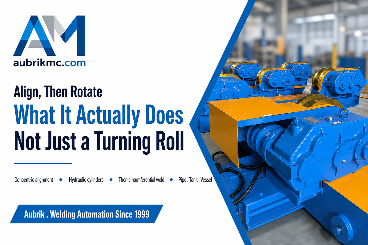
A fit-up rotator is a turning roll with a second job. A plain rotator only spins a round part so the torch can lay a continuous seam; a fit-up rotator does that too, but first it brings two separate sections into concentric alignment – hydraulic cylinders under the roller groups raise, lower and shift each shell until the bores line up and the edges meet within tolerance.
In catalogue language it shows up as a hydraulic shell-to-shell fit-up rotator, a fit-up welding rotator, or a set of tank fit-up rolls, and by the part it carries as tank turning rolls, pipe turning rolls, or vessel turning rolls – the same machine sized for a different job.
One distinction saves buyers a wrong order: a fit-up rotator aligns, but it usually does not weld on its own. In most shops it works with a conventional welding rotator or a self-aligning rotator-the fit-up unit walks the two cans concentric and holds them for tacking, then a standard turning roll turns the tacked assembly under the arc. Some heavier beds combine both functions, but the division of labour is worth keeping straight when you spec a line: fit-up handles the alignment problem, the turning roll handle the rotation problem. If you want the wider family first, our guide to how welding rotators and turning rolls work covers every rotator type, and the full welding rotators and turning rolls range shows where fit-up sits.
Why does that alignment step matter enough to power it hydraulically? Because the hard part of joining two shells isn’t turning them-it’s getting the two edges concentric before any metal is deposited. Two rolled cans are never perfectly round, so their edges meet with a step (hi-lo) and a variable gap. Correct that by hand with a crane and wedges and you tie up a hoist and a crew; correct it with hydraulics on the bed and one operator does it in minutes. That’s the whole reason the machine exists.
Inside the Machine: The 3-Axis Fit-Up Envelope
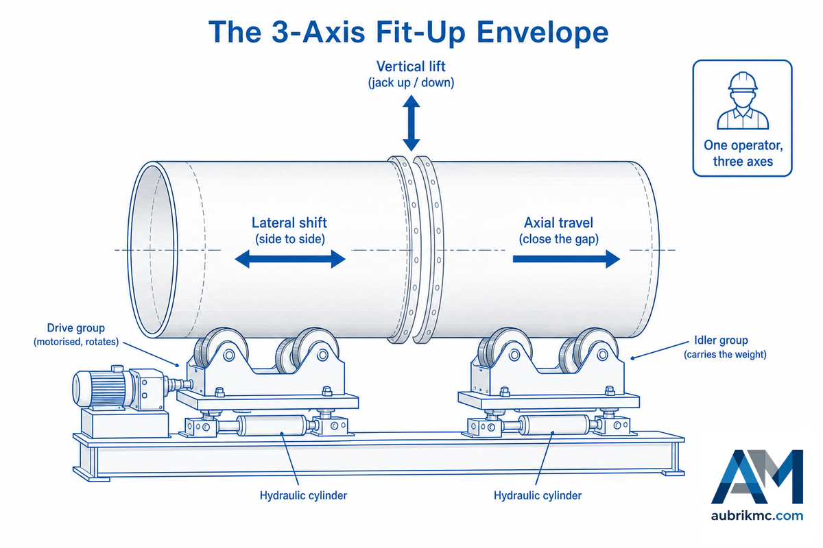
Strip away the marketing and a fit-up rotator give one operator a small, precise space to move a heavy shell in. We call it The 3-Axis Fit-Up Envelope: the three directions the hydraulics can walk an edge into place, versus the single fixed axis of a plain roll. On the highest-scoring competitor bed, the operator can “independently lift, lower, or shift the workpiece” to correct misalignment and gap between sections – that’s the envelope in a sentence.
Those three axes are simple once named. Vertical lift raises or lowers each roller group on its cylinder, so a low edge comes up to meet a high one and the hi-lo step close. Lateral shift moves a roller group sideways – on a horizontal fit-up rotator the rollers travel toward the center to lift the workpiece and outward to lower it; on a vertical fit-up rotator each side’s rollers move up and down independently – so the two bores come coaxial. Axial travel appears on a traveling growing-line bed, where one unit rolls on rails to close or open the gap between sections along the seam axis. Together those three let the operator resolve the seam to well under 1 mm before locking it.
📐 Engineering Note
This mechanized align-then-rotate approach is documented, not a vendor flourish: patent AU 2021229209 A1 sets out placing a pipe segment on an alignment device before an internal welding head runs the joint. Because the correction is powered rather than craned, the operator can hold pressure on the seam while tacking – the load never hangs from a hook during alignment, which is where hand fit-up gets both slow and dangerous.
How does a fit-up rotator move two heavy shells into alignment?
Each roller group sits on a hydraulic cylinder tied to a pump station and a remote, cable or wireless. Working the pendant, the operator jogs one edge up, down or across in small increments, reading the step at the seam with a hi-lo gauge, until the two shells share one centerline.
Idler groups carry and steady the weight; the powered rollers later turn the tacked assembly. Some beds run two roller beds with four independent hydraulic-adjust rollers and need no rail; others use one ground-fixed unit plus one rail-traveling unit for the axial move. Control is deliberately fine because the target – a sub-millimeter seam – is unforgiving.
The Hi-Lo Tolerance Stack: What the Codes Require Before the Tack
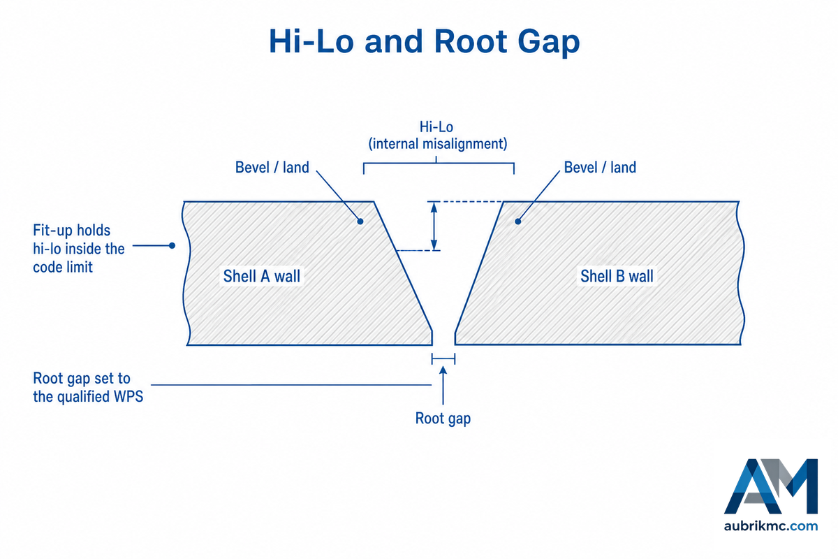
fit-up quality is judged by two numbers: hi-lo – the internal misalignment, or step, between the two bores – and the root gap between the edges. Hi-lo is simply the difference between the internal (or external) heights of two pipes; poor alignment leaves a weaker, harder-to-inspect weld. The rotator’s job is to hold both inside whatever the governing code allows. Here’s where most guides oversimplify: the codes don’t all publish a single fixed hi-lo number. Some give a hard figure; the most-cited one deliberately doesn’t.
| Standard | What it governs | Internal misalignment (hi-lo) rule | Root gap / fit-up note |
|---|---|---|---|
| ASME B31.3 | Process piping | No fixed number — fit-up per the weld joint design/WPS, smooth internal transition | Per joint detail; flange faces within 1/16 in./ft (0.5%) |
| ASME B31.8 | Gas transmission pipe | ≤1/8 in (3.2 mm) below 20% hoop stress; ≤3/32 in (2.4 mm) at/above 20% | Above the limit, taper the thicker wall 3:1 (30° max) |
| API 1104 | Pipeline girth welds | Governing acceptance standard; misalignment commonly held to ~1/8 in (3 mm), then flushed | Root gap set by the qualified procedure |
| ASME BPVC Sec VIII | Pressure vessels | Alignment tolerance (PW-33) banded by wall thickness and joint category | Offset limits tighten as wall thins |
| AWS D1.1:2025 | Structural steel | Fit-up and misalignment per the code’s joint details and acceptance | Root opening per prequalified/qualified joint |
| ISO 3834 + ISO 15614 | Weld quality system + WPS/WPQR | No numeric hi-lo; requires qualified procedures that fix the fit-up | Root gap defined in the qualified WPS |
| EN 1090 | EU structural execution | Execution class (EXC1–4) sets the weld-quality tier via ISO 3834 | Fit-up tolerances flow from the execution class |
| Flange alignment (B31.3 §335) | Flanged joints | Faces aligned within 1/16 in./ft; bolt holes within 1/8 in (3.2 mm) offset | Verified before bolt-up, not welded |
| Typical field root gap | Per WPS (not a fixed code number) | — | ~1.5–3.0 mm (1/16–1/8 in), process-dependent |
| Typical field hi-lo | Per WPS (not a fixed code number) | Often held ≤~1.6 mm (1/16 in); tighter on thin wall | — |
Arrange code rules per ASME B31.3 and B31.8 (as compiled in the LANL Engineering Standards guides); API 1104 and BPVC figures per those standards. Both “typical field” rows are typical WPS practice, not fixed code limits – confirm the number against your own qualified procedure.
Read it as an applied number. On a 12mm-wall gas line under ASME B31.8, an internal offset over 1/8in (3.2mm) requires a re-bevel or a 3:1 taper; push that line above 20% of hoop stress and the ceiling tightens to 3/32in (2.4mm). A hydraulic fit-up rotator earns its place by aligning the two bores concentric so the seam sit well inside that window – often under 1mm – before a single tack freezes it in place. The lesson under the entire table: B31.3 won’t hand you a hi-lo number, so the real acceptance limit lives in your qualified procedure, and the rotator must hit whatever that procedure states.
Using a Fit-Up Rotator: The First-Tack Alignment Sweep

Sequence matters more than the machine. If you get the order wrong – tack before you hi-lo-out – you sit on an out-of-tolerance offset that no turning will fix; the only solution is to grind the tacks out and re-install. That’s the most frequent and most costly fit-up error on the floor. The ordered pre-tack routine below – The First-Tack Alignment Sweep – is the piece worth taping to the bed.
- Load and seat. Crane the first section onto the idler carriages; allow it to settle so the rollers cradle the shell.
- Bring in the second can. Float the mating section on the fit-up rollers and close the gap along the seam axis.
- Close the root gap. Set the edge-to-edge opening to the qualified WPS value (usually ~1.5-3.0mm), checked at several clock positions.
- Correct the hi-lo. Jog the vertical and lateral cylinders until the internal step read within tolerance on a hi-lo gauge, all around.
- Check ovality. Rotate slowly and observe the step at 3, 6, 9 and 12 o’clock; an out-of-round section requires re-clocking, not more force.
- Tack the pattern. Place 4-6 tacks evenly around the joint to secure the alignment prior to any full pass – the practice code-compliance fitters use to hold the seam.
- Jog-rotate and weld. Present the tacked assembly to the turning roll and run the circumferential weld at a surface speed matched to the welding process.
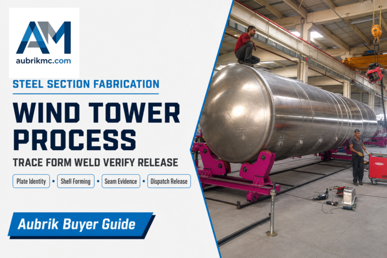
Here’s a visual on the real shop floor. A fitter will walk a 3.5m diameter can on to a hydraulic bed and against the prior section in a wind tower shop, will clamp it up on the rail axis and then use the vertical cylinders walking a 4mm step to get it to sub-1mm prior to the hi-lo gauge reading green at each clock position. Tacks go in next – six evenly spaced ones – and the new can is a section on the growing tower. By then the crane is already on the next can. No hanging is needed while aligning this is the safety and speed win. The operating detail of turning the tacked can, our pipe rotator for welding guide goes over setting speed to RPM, and a heavier job will likely be aided with a column and boom welding manipulator for the weld itself.
⚠️ Common misconception
“The rotator will pull it round.” No. It won’t. A fit-up rotator will correct the step and the joint gap, but not re-round a badly out of round can. if it’s too oval for the roller to correct the repair need to happen on the rolling equipment; the can has to be re-rolled or re-clocked – not have more hydraulic pressure which just mars the shell.
Fit-Up Rotator vs Line-Up Clamps: The Clamp-to-Rotator Crossover
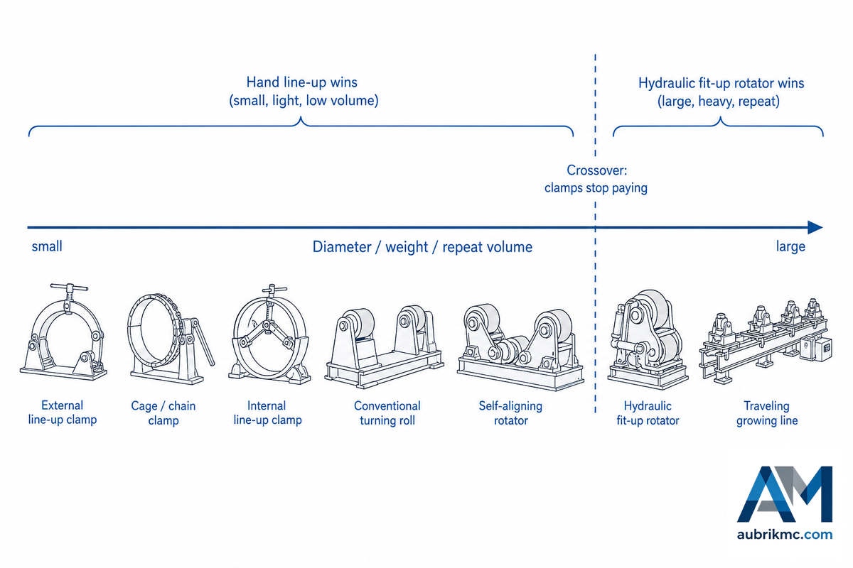
A hydraulic fit-up rotator isn’t always the answer-and saying that’s the honest bit of many vendor pages. On small pipe that can be done by hand, an internal or external line up clamp gets the joint round much faster and for a fraction of the price. Rotators make sense at a diameter, weight, or repeated volume where re-clamping and craning are the bottlenecks. One published study from SPE’s Journal of Petroleum Technology described manual fit-up of vessels as “a long and labor-intensive process often requiring three to four laborers and 3 to 6 hours”. That one study may not represent every situation but you can see the potential labor cost in large sections. A single-operator hydraulic bed eliminates that cost – this is why it’s a crossover.
The Fit-Up Tooling Spectrum
| Tool type | Typical diameter / duty | Alignment axes | Who moves the weight |
|---|---|---|---|
| External line-up clamp | Small–mid pipe, portable | Radial pull only | Fitter, by hand |
| Cage clamp | Field pipeline, uniform OD | Full-circumference squeeze | Fitter, by hand |
| Chain / wrap clamp | Small pipe, tight spots | Radial cinch | Fitter, by hand |
| Internal line-up clamp | Mid–large pipeline bore | Internal radial expansion | Clamp bears from inside |
| Conventional turning roll | Any round part, one diameter | Rotation only | Bed carries; crane aligns |
| Self-aligning rotator | High-mix diameters, thin wall | Rotation + auto-diameter | Bed carries; crane aligns |
| Hydraulic fit-up rotator | Large cans needing concentric tack | Vertical + lateral (+ rotation) | Bed lifts, shifts and turns |
| Traveling growing-line rotator | Long towers/vessels, section by section | Vertical + lateral + axial travel | Bed does all axes; crane freed |
| Tank fit-up rolls | Large-diameter tanks, thin wall | Vertical + lateral (+ rotation) | Modular beds, added per section |
So what’s the crossover? The Clamp-to-Rotator Crossover is the region where clamping and craning lose their value; this is where the diameter goes beyond a fitter’s easy handling, section weight starts to make every re-clamp a crane lift, or sheer volume makes setup the line’s bottleneck. Above the line it make sense to get the hydraulic fit-up rotator, allowing one operator to replace 3-4 labor hours; below the line it’s quicker and cheaper to use clamps. For example, one welding-automation vendor reports cutting welder time by up to 65% on automated wind-tower fit-up versus its manual line-up. Review the two columns below and apply it to your situation.
✔ A fit-up rotator pays when…
- Heavy enough sections make re-clamping a crane pick.
- Volume (towers, tanks, vessels) within the same diameter class.
- Thin or coated shells need a spread, low-mark contact
- A fixed head or column-and-boom follows the fit-up
⚠ A line-up clamp still wins when…
- Pipe is small enough to align by hand
- One-off or field work (rather than a shop line)
- Budget or floor space rules out a powered bed
- Diameters vary so widely no single bed covers them
This is a purchasing decision, and tonnage-to-model selection is handled on the product pages, not here: hydraulic fit-up rotator capacity charts live on this page. If your work is more about swapping out diameters than aligning seams, then the self-aligning rotator drive is more relevant reading, and if the workpiece must be tipped over rather than turned, then see the pipe welding positioner instructions – positioner grasps and angles workpiece, where rotator can turn a long round cylinder free.
Configurations & Capacity: Horizontal, Vertical & the Growing Line

Fit-up rotators can be driven with any of three kinds of mechanism, named after how they advance the shell: horizontal fit-up rotator rollers advance to the center, then pull back to bring two workpieces into line; a vertical fit-up rotator raises each roller group independently, then the groups converge on the centerline. Beds come with two pairs of self-aligning rollers or just one on a ground rail track. Use ground rail tracking where the sections meet along the axis.
This latter configuration is the growing line, or some call it a fit-up bed, because a group of cans or a tower section, usually up to about 30 meters, are manually or mechanically pulled into alignment as a long vessel, or the centre of a wind-tower, before being tack-welded section by section. Instead of repeatedly rigging a hoist on each section and then picking it into position for a crane operator to align, fine adjustment of the sections is accomplished with mechanisms built into the bed. Moving-bed fit-up provides flexibility, frees up the hoist and minimizes loads on the alignment cranes. They form the heart of many tower and tank lines.
📐 Engineering Note
The limit is capacity rather than diameter, and diameter itself follows from the roller-center spacing. Published tonnage bands for the fit-up rotator range from about 2-1,200 tons, and each model covers only a slice of that band, set by its capacity and roller spread. So it isn’t simply a question of raw tonnage, but also one of your heaviest section plus its tooling, divided by the distance between your two largest section rollers (i.e., minimum and maximum diameter), then reading that on a specific model. We do a load test for each unit in our inventory throughout its working range before it ships because a hydraulic that binds under an off-center load is useless. Adjustable hydraulic height adjustment lets one operator dial a 10 tons-class shell into place with the precision and efficiency a manual crew cannot match.
As a welding-equipment supplier to the manufacturing industry, Aubrik builds fit-up beds as one of three welding-rotator types – Self-Aligning, Conventional, and hydraulic fit-up – across its welding rotators and turning rolls line, with high-quality, long-lasting construction and customization for various industries, from a tank rotator to a full welding machine cell. Matching configuration to task – fit-up for alignment, then conventional or self-aligning to rotate the part – is the point; your size and volume decide which capacity you read on a model rather than a whole catalogue range.
Where Fit-Up Rotators Earn Their Keep

Fit-up rotators come in wherever the end of one shell joins another of big diameter and the girth seam needs to be concentric. Those obvious examples all share one thing: they’re too big or too heavy to centre by hand and there are so many that a motorised bed can be justified for the welding operations that follow on these cylindrical workpieces.
- Pressure vessels & boilers. Multi-course shells that must meet BPVC alignment limits before the longitudinal and girth welds.
- Storage tanks. Large-diameter, thin-wall courses where a spread contact protect the surface – modular tank fit-up rolls added per section.
- Wind towers. Growing-line assembly of ~30m sections – the energy-transition work sizing the biggest beds.
- Pipe spools & pipe lines. Girth joints held to API 1104 or B31 limits, tacked concentric on a pipe fit-up rotator before the rotated weld.
- Heat exchangers, LPG bullets, shipbuilding, oil & gas. Cone and cylinder joints where concentricity drives inspection pass rates.
“The jobs that justify a fit-up bed are the ones where the crane was doing the alignment. Move that step onto the rollers and you free the hoist, take the load off a suspended sling, and let one operator hold the seam under a millimetre while the tacks go in. That is where the hours come back.”
Aubrik Engineering Team, Wuxi ABK Machinery
Rollers, Maintenance & the Honest Limits

Two roller faces cover most fit-up work, and the choice follows the shell, not a blanket preference. That trade pits load capacity against surface protection, measured by durometer under ASTM D2240.
✔ Polyurethane (PU) rollers
- Protect thin-wall and coated shells from indentation
- Better grip, less slip on a lightly unbalanced load
- Damp vibration and noise
- Wear faster, the tyres are a replaceable consumable
⚠ Steel-faced rollers
- Carry the heaviest fit-up load per wheel
- Tolerate the heat near a heavy weld zone
- Longer life under abrasive service
- Higher point load – scuff or dent risk on thin, polished shells
Maintenance is light but non-negotiable: keep the roller frame clear of obstruction, grease the gear at first use and oil the bearings daily, change the reducer oil on a monthly cycle, and confirm no loose fasteners and a load within the bed’s rating before every run. Replace PU tyres as they wear – they’re the part most likely to fail first.
Now the limits vendors rarely list. Fit-up rotators make straight, circumferential joints – they rotate the part to bring the seam to the torch, so they don’t do complex or non-linear welds. It usually needs a companion turning roll to run the weld after the tack. And it’s capital equipment: below the crossover, a clamp is the better spend.
⚠️ Machine safety, not just weld quality
A fit-up rotator adds powered lift, lower and lateral hydraulics on top of rotating rollers, so it carries more contact and control hazards than a plain bed. Under U.S. machine-guarding rules in OSHA 29 CFR 1910.212, rotating parts and ingoing nip points that can contact an operator must be guarded, and the hydraulic axes must be locked out for setup. On automated lines the control system itself carries a duty – risk assessment under ISO 12100 and safety-related control reliability under ISO 13849-1 – because a lift or shift command that misfires under a suspended load is a serious event, not a nuisance.
Where Fit-Up Rotator Demand Is Heading

What changed in 2026 isn’t a headline on market size. It’s about who’s performing the fit-up work and the way buyers find the machine. For instance, the number of generic searches for welding rotator and turning rolls decreased year-on-year (between about one third and nearly half), whilst the number of searches including the fit-up method or clamp-type phrases remained constant or rose – fit up clamp is up around a third.
Buyers now search for the fit-up method they already know they want and read a definitive answer from the AI summary before they ever click. That shifts procurement risk from brand to specification: buy a hydraulic bed too heavy for small-pipe work and it sits idle, or under-buy a clamp when a growing production line really needed the powered bed.
Under that runs a labor signal with fangs. BLS projects welders, cutters, solderers, and brazers to grow only 2% between 2024-2034 (slower than average) and notes that welding automation can restrict demand. For an industry already short of competent fitters, that is the structural reason single-operator hydraulic fit-up is rising: it collapses a 3-4 person alignment crew to one operator and a bed. That is reduced labor and reducing manual handling on the exact concentric weld seam the codes require.
Automated fit-up cells – laser-guided precise alignment with integrated SAW and GMAW automatic welding – are the automation-equipment answer to a non-expanding headcount, pushing slow manual welding toward efficient welding with precise control and consistent rotation. These automation systems lean on advanced technology, but the case stays simple: industry monitors put the pipe-welding-rotator segment near USD 1.04B by 2025 at roughly 7% annual growth (wind-tower fabrication higher), so treat that as guidance, not exactitude. Buy for the fit-up approach and code-driven seam construction, size the heavy section, and let the crossover – not a brochure – decide a bed-versus-clamp spend.
Frequently Asked Questions
Q: What is the purpose of a fit-up rotator?
View Answer
In the case of a fit-up rotator, a pipe, tank, or pressure-vessel cylinder section(s) is aligned concentrically and welded with the next, which is then rotated for circumferential weld. Built-in hydraulic cylinders raise, lower, and slew each roller assembly so an operator can dial in alignment (correcting hi-lo) and set the root gap prior to the first tack. The method replaces the slow crane-dependent manual positioning method that would keep a crew busy.
Q: How is a fit-up rotator different from other welding rotators?
View Answer
Standard or self-aligning rotator can only rotate the round piece during the welding phase; however, the addition of power to the fit-up rotator, includes moving hydraulics to raise, lower, and reposition the rollers so two shell pieces may be aligned coaxially and tack welded; In the real world the fit-up unit typically handles alignment, and a standard or self-aligning turning roll handles the rotation for the welding – these two items are generally purchased and used together rather than replacing one another.
Q: Are fit-up rotators the same as welding positioners?
View Answer
No. A welding positioner clamps a piece on a table or headstock and tilts and rotates it to bring a weld to a flat position, and it can handle many shapes. A fit-up rotator works only on round, cylindrical sections: it rolls them freely to lay a continuous circumferential seam and, unlike a positioner, corrects the concentric alignment of two shells before the tack. Round and long goes on a rotator; tip-and-rotate goes on a positioner.
Q: What is the difference between a horizontal and a vertical fit-up rotator?
View Answer
A horizontal fit-up rotator moves its rollers toward the centre to lift the workpiece and outward to lower it; a vertical fit-up rotator raises and lowers each side’s rollers independently. Both dock two workpieces to a common centreline – they differ in the geometry of the lift.
Q: How much weight can a fit-up rotator handle?
View Answer
Vendor-published ranges span roughly 2 to 1,200 tons, model-dependent, with custom builds above that. But the rating assumes a centred load: an off-centre section cuts usable capacity sharply, so size from the heaviest section plus its fixture and apply a safety factor rather than reading the headline tonnage. The tonnage-to-model match is a sizing question best handled on the product page against a specific bed.
Q: What are the cons of a fit-up rotator?
View Answer
Three honest limits. First, it makes straight, circumferential joints only – it rotates the part to bring the seam to the torch, so it does not do complex or non-linear welds. Second, it usually needs a companion conventional or self-aligning turning roll to run the weld after the tack, so it is one part of a cell, not the whole cell. Third, it is capital equipment with powered hydraulics that add guarding and control-safety duties (OSHA 1910.212, ISO 13849-1) and maintenance; below the diameter-and-volume crossover, a hand line-up clamp aligns the joint faster and far cheaper. Match the tool to the part: big, heavy, repeating sections justify the bed; small hand-handled pipe does not.
Why We Wrote This
We build fit-up rotators in Wuxi and see the same two errors repeat: treating the bed as a substitute for a turning roll, and buying hydraulics for work a hand clamp would align faster. This guide keeps the alignment problem and the rotation problem separate, pins the tolerance to the code that actually governs your seam (including the fact that ASME B31.3 hands you no fixed hi-lo number), and draws the crossover where a clamp stops paying.
Reviewed by the Wuxi ABK Machinery Co., Ltd. technical team.
References & Sources
- ASME B31.3, Process Pipingthe governing code (fit-up per the weld joint design); rules as compiled in the LANL Engineering Standards B31.3 guide
- ASME B31.8, Gas Transmission & Distribution Pipinginternal offset & taper limits; as compiled in the LANL Joint Fit-Up and Alignment guide
- AWS D1.1/D1.1M:2025, Structural Welding Code, SteelAmerican Welding Society
- OSHA 29 CFR 1910.212, General Requirements for All Machines (Guarding)U.S. Occupational Safety and Health Administration
- Patent AU 2021229209 A1, Rotating Welding System and Methods (alignment device + internal weld head) — via Google Patents
- Automated Welding for Pressure VesselsSPE Journal of Petroleum Technology (manual fit-up labour & time)
- Welders, Cutters, Solderers & Brazers, Occupational OutlookU.S. Bureau of Labor Statistics (2024–2034 projection)
Related Articles
- Hydraulic Fit-Up Rotator, specs, tonnage & sizing
- Self-Aligning Welding Rotator, mechanism, types & field diagnosis
- How welding rotators and turning rolls work, the category guide
- Pipe rotator for welding, setup and operating guide
- Welding turntable selection guide
- Heavy-duty welding positioner, when to tilt instead of turn