Get in Touch with Aubrik Company

Welding Rotator Design: Engineering Calculations, Roller Geometry, and Heavy-Duty Sizing Guide

Industrial welding rotator design governs how a powered drive unit and free-wheeling idler roller bed support, rotate, and align cylindrical workpieces. Proper frame and roller geometry help distribute loads and control axial drift. Shell stiffness, roller alignment and workpiece roundness also impact stability during welding operations. Aubrik turning rolls span 1 to 1,000 metric tons across the standard and custom ZT/AD series (with HGKF/ZDG fit-up systems reaching 2,000 T) and 200 to 6,000 mm workpiece diameter. Sound mechanical design balances three coupled variables. Engineers size normal roller load across a 60° to 120° included cradle angle. They also determine peak eccentric drive torque with a 1.5× overload factor and match polyurethane or forged steel wheels to preheat temperatures.
Selecting a rotator by static weight alone stalls drive motors on heavy welding projects. Unlike a tilting welding turntable used for flat flanges, turning rolls cradle long shells on their horizontal axis for heavy welding tasks. This ultimate guide covers our eccentric torque and rolling drag sizing method, the 4-Angle Roller Load Selector, and conditional ±1 mm anti-drift control systems. These rules boost welding productivity across different welding and modern welding fabrication lines.
Core Architecture of Industrial Welding Rotator Design: Drive Bed, Idler Bed, and Frame Mechanics
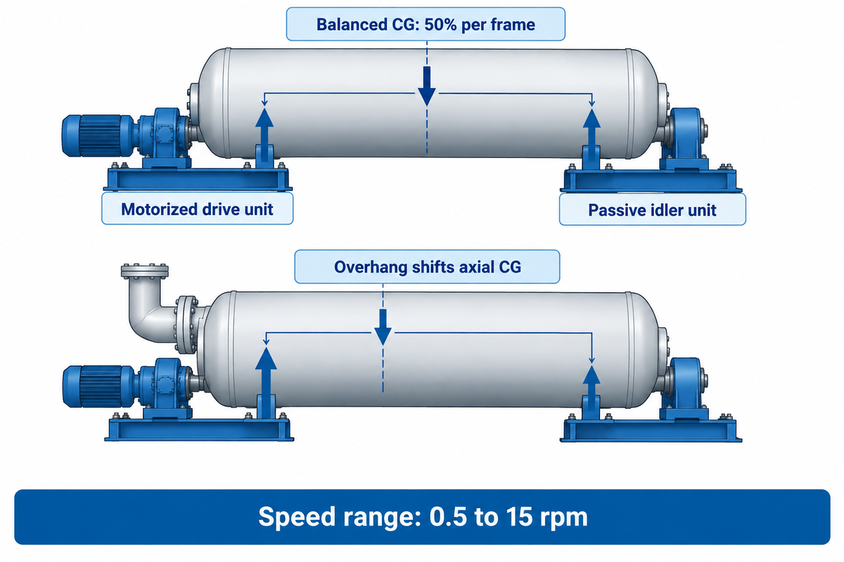
An industrial welding rotator pairs one motorized drive unit with at least one idler unit to rotate cylindrical components for heavy welding work. The drive unit incorporates twin AC variable frequency motors, a planetary or worm reducer, and driven roller shafts. The idler unit carries passive wheels that support the rest of the shell mass along a fixed centerline. These welding rotator machines hold the weld seam steady for an automatic welding machine or submerged arc process. A welder can then control the welding process from a single position with consistent rotation speed.
Static load sharing between the drive bed and idler bed reaches 50% per frame only when the center of gravity sits dead-center. In a two-bed configuration, a heavy dish head, manway or nozzle overhang can change the axial center of gravity. Each bed’s static reaction then becomes unbalanced due to lever-arm geometry. It is equal to the total weight times the center of gravity’s distance from the opposing bed, divided by bed spacing. The ASME Journal of Pressure Vessel Technology paper on local shell flexibilities quantifies how concentrated support reactions bend thin cylindrical walls. Frame fabrication must limit beam deflection so roller tires contact the shell evenly. Shop practices that use welding rotators with rigid beds protect welding quality on every pass.
For heavy loads, industrial welding rotators and turning rolls built by Aubrik since 1999 use stress-relieved fabricated steel box frames. As noted in the Wuxi ABK 200-ton heavy-duty welding rotator technical guide, cast bearing housings can crack under cyclic stress on 180-ton wind tower base sections. Aubrik claims that all frames in the 1 to 1,000 T range pass a 1.5× static overload test, and lists 24-hour continuous-duty operation. Stepless variable speed control regulates roller rotational speed within the range of 0.5 to 15 rpm to attain consistent weld quality. This steady roller motion supports high-quality weld beads on thick pressure vessels and improves productivity and weld integrity.
Self-Aligning vs. Conventional Leadscrew-Adjustable Welding Rotator Designs
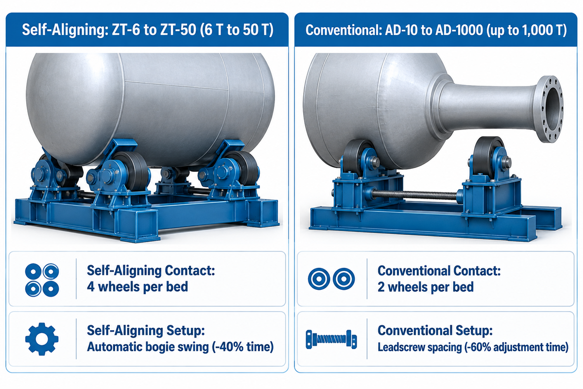
Fabrication managers compare two primary types of rotators and types of welding rotators when fitting a bay: four-wheel self-aligning rotators and two-wheel conventional rotators. Choose four-wheel self-aligning rotators for quick diameter changeovers on thin shells. Aubrik’s ZT-6 to ZT-50 series covers 6 to 50 T, while some industry self-aligning designs top out at 300 to 500 tonnes. Choose conventional adjustable rotators for long necked nozzles on heavy vessels that require attachment clearance.
When Does a Self-Aligning Rotator Outperform a Conventional Turning Roll Bed?
A self-aligning welding rotator outperforms a conventional leadscrew-adjustable turning roll bed when a shop runs frequent diameter changes across thin shells without nozzle interference. This design covers the range of 6 T to 50 T in Aubrik’s standard ZT series, and up to 300-500 T in other self-aligning designs. They cradle the shell as soon as the workpiece is loaded by crane. That geometry eliminates the need to make manual adjustments within the swing range of the bracket. It also splits radial contact force across four wheel faces per bed to raise production efficiency.
On mixed-batch lines, ZT Series self-aligning welding rotators remove manual bolt re-pinning between boiler tubes and tank cans. In an Aubrik wind tower run using eight ZT-50 units on 120 m tower sections, automatic alignment cut setup time by 40%. Overall line throughput rose by 35%. However, upper bogie wheels sit higher on the shell flank and can strike protruding nozzles. Vessels with long nozzle necks need wider lower clearance. Here, AD Series adjustable turning rolls use leadscrew or bolt spacing to clear attachments. Standard AD models span 10 to 60 T, while custom synchronized builds reach 200 to 1,000 T. On a five-unit AD-30 pressure vessel line, leadscrew spacing with remote control cut per-workpiece adjustment time by 60%.
| Design Parameter | Self-Aligning Rotator (Aubrik ZT-6 to ZT-50) | Conventional Adjustable Rotator (Aubrik AD-10 to AD-1000) |
|---|---|---|
| Standard Load Capacities | 6 T to 50 T in Aubrik ZT series (300–500 T industry ceiling) | 10 T to 60 T standard; 200 T to 1,000 T custom synchronized |
| Roller Contact Points per Bed | 4 wheels per bed (8 contact faces per 1D+1I set) | 2 wheels per bed (4 contact faces per 1D+1I set) |
| Diameter Changeover Setup | Automatic bogie swing within each model’s rated diameter window | Manual bolt shift or motorized leadscrew spacing adjustment |
| Local Shell Bending Stress | Lower radial load per wheel (load split across double bogie wheels reduces local shell flexing) | Higher load per wheel (suits thick-wall carbon steel) |
| Nozzle & Manway Clearance | Restricted along mid-flank arc by upper rocker wheels | High clearance (low-profile two-wheel cradle clears long necks) |
| Best Industrial Applications | Thin-wall stainless tanks, boiler tubes, mixed-batch wind cans | Heavy ASME pressure vessels, 180 T wind tower bases, nuclear drums |
Engineering Calculations for Drive Torque, Motor Power, and Eccentric Center of Gravity
Sizing welding equipment by nominal tonnage alone fails when heavy manways, internal trays, or offset nozzles shift the center of gravity. As shown in the Cyclotron welding positioner capacity calculation guide, a 4,000 kg workpiece fitted with 600 kg of clamps and fixtures creates a 4,600 kg operating load. That guide applies a 1.5 factor of safety up to 15 tons and 1.2 above 15 tons. For critical eccentric duty on a weld positioner or turning roll, the safety factor rises to 2 or 3.
How Do You Calculate Drive Torque for an Eccentric Pressure Vessel on Turning Rolls?
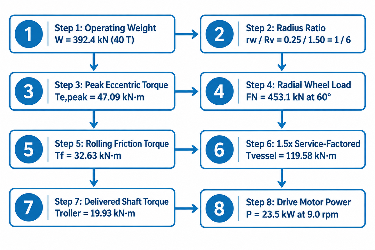
Torque for an eccentric pressure vessel on turning rolls combines three terms: peak eccentric gravitational torque (Te, peak = W × e), rolling friction torque (Tf) and startup inertia torque (Ti). The torque sum is then multiplied by a continuous-duty service factor of 1.5 and the roller-to-vessel radius ratio (rw / Rv). This radius conversion gives the required delivered torque at the driven roller shafts (19.93 kN·m in the 40-ton worked example below). Dividing by 0.80 drivetrain efficiency yields an equivalent input torque of 24.91 kN·m referred to the roller shaft. The motor input power is therefore (Troller × nroller) / (9550 × η), where η is the motor efficiency.
Rotational mechanics in the University of New South Wales torque equilibrium reference sets gravitational torque as τ = W × e × sin θ. It hits its peak value Te,peak = W × e when the radial offset arm e is horizontal (sin 90° = 1). If rolling friction is calculated separately, then the only extra torque during startup is inertia torque (Ti). It is negligible relative to that of eccentric gravitational torque only when the variable frequency drive (VFD) acceleration ramp is sufficiently gradual. Also the U.S. Department of Energy OSTI review of nuclear reactor pressure vessel welds, shows the importance of steady rotation. Speed hunting during welding changes travel speed and heat input, which increases the risk of slag inclusions and lack of fusion.
| Calculation Step | Formula / Input Parameter (Assumed Example Inputs) | Computed Engineering Value |
|---|---|---|
| 1. Total Operating Weight (W) | m = 40 T (40,000 kg vessel + internal stiffening spiders) | W = 392.4 kN |
| 2. Vessel & Roller Geometry | Vessel OD Dv = 3,000 mm (Rv = 1.50 m); Roller OD dw = 500 mm (rw = 0.25 m); Included angle θ = 60° | Radius ratio rw / Rv = 0.25 / 1.50 = 1 / 6 |
| 3. Term 1: Peak Eccentric Torque (Te,peak) | Radial CG offset e = 120 mm (0.12 m) at horizontal 90° arm: Te,peak = W × e | 392.4 × 0.12 = 47.09 kN·m |
| 4. Total Radial Wheel Load (FN) | Summed across drive and idler stations at 30° half-angle: FN = W / cos 30° = 392.4 / 0.866 | FN = 453.1 kN |
| 5. Term 2: Rolling & Bearing Friction Torque (Tf) | Lever arm μr + fb × rshaft = 0.012 m; Ratio 0.012 / 0.25 = 0.048; Drag Ft = 453.1 × 0.048 = 21.75 kN; Tf = Ft × Rv | 21.75 × 1.50 = 32.63 kN·m |
| 6. Service-Factored Vessel Torque (Startup Inertia Neglected) | Apply 1.5× continuous-duty service factor with gradual VFD ramp (Ti ≈ 0): Tvessel = 1.5 × (47.09 + 32.63) | Tvessel = 119.58 kN·m |
| 7. Delivered Roller Shaft Torque (Troller) | Troller = Tvessel × (rw / Rv) = 119.58 × (0.25 / 1.50) | Troller = 19.93 kN·m (24.91 kN·m referred input at 0.80 efficiency) |
| 8. Drive Motor Power (P) at Indexing Speed | At a vessel speed of 1.5 rpm and a roller speed of 9.0 rpm, with drivetrain efficiency η = 0.80: P = (19.93 × 1,000 × 9.0) / (9550 × 0.80) | P = 23.5 kW |
Illustrative engineering inputs for this 40-ton example include vessel dimensions, 120 mm radial center-of-gravity offset, and 0.80 drivetrain efficiency. Actual drive motor size must be determined by assessment of the vessel drawing’s measured eccentricity and gearbox reduction ratio.
Roller Included Angle Geometry and Wheel Material Selection: Polyurethane vs. Forged Steel
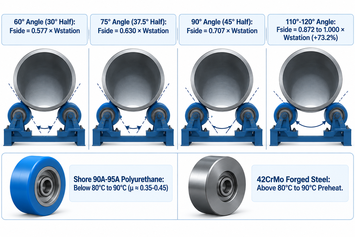
There are two factors that affect contact stress at the wheel-to-shell track: the included cradle angle and roller material hardness. For thin-walled unheated stainless or aluminum vessels, specify a 60° to 75° full included roller angle (30° to 37.5° half-angle). Pair that angle with Shore 90A to 95A cast polyurethane wheels to minimize radial pinching stress. For preheated thick-walled steel vessels above 80°C to 90°C track temperature, specify a 75° to 90° full included roller angle (37.5° to 45° half-angle). Use induction-hardened forged steel wheels to prevent delamination of the elastomer and boost lateral stability. Note the differences in how catalogs illustrate angles. Some list a 30° to 45° half-angle (α = θ / 2 from the vertical vessel centerline to one roller). Other drawings specify a 60° to 120° full included angle (θ = 2α between left and right rollers).
The 4-Angle Roller Load Selector is used to set wheelbase spacing. Let Wstation be the vertical load on one cradle station. When a balanced shell is supported by one drive bed and one idler bed, Wstation = W / 2. The normal radial reaction on that side is Fside = Wstation / (2 cos(θ/2)).
- 60° Included Angle (30° Half-Angle – Fside = 0.577 × Wstation): Lowest radial pinching force. Use this angle for thin aluminum or stainless shells to prevent them from tipping over.
- 75° Included Angle (37.5° Half-Angle – Fside = 0.630 × Wstation): Used for medium wall carbon steel pressure vessels and pipe spools, as well as moderately pre-heated shells.
- 90° Included Angle (45° Half-Angle — Fside = 0.707 × Wstation): High lateral stability for preheated thick-walled pressure vessels, large workpiece diameter wind tower cans, and eccentric vessels.
- 110° to 120° Included Angle (55° to 60° Half-Angle – Fside = 0.872 to 1.000 × Wstation): Extreme wedging force. Widening the cradle from 60° to 120° raises normal wheel load by 73.2%, which requires checking local shell buckling and stiffness before loading thin walls.
In regards to wheel material selection, surface finish and preheat rules apply. Cast polyurethane rollers (Shore 90A to 95A) provide high traction (coefficient of friction μ ≈ 0.35 to 0.45) to reduce slippage during rotation. They also protect stainless steel from carbon contamination. However, machinists in the Practical Machinist tank turning roll wheel repair forum thread report urethane tires delaminating from steel hubs under radiant preheat or static overload. Lab testing in the University of Modena study on metal-elastomer adhesive bond shear strength confirms that bond life requires shot-blasted steel cores, cured adhesives, and controlled joint temperatures. Keep polyurethane below 80°C to 90°C continuous track temperature. Forged steel wheels such as 42CrMo suit preheated-vessel service when contact heat exceeds the 80°C to 90°C polyurethane tire or adhesive bond limits. Polyurethane wheels can carry heavy vessels as long as individual wheel loads, contact temperatures, and contact times remain below the wheel assembly’s ratings.
Axial Spiral Drift Mechanics and Anti-Drift Roller Control Systems
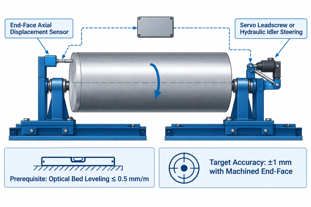
A rotating shell can creep along roller faces like a screw thread during long circumferential welds. As noted in the RESIZEWELD engineering analysis of anti-drift welding rotators, axial drift ruins seam tracking and forces operators to stop submerged arc passes. Left unchecked, heavy shells can walk off the roller faces.
How Do Anti-Drift Welding Rotators Stop Axial Vessel Creep During Circumferential SAW?
Axial drift is combatted by electronic control systems that sense longitudinal shell movement at the end of the vessel. This measurement is used to steer the idler rollers. A servo leadscrew or hydraulic cylinder steers the idler Bracket by a fraction of a degree. This micro-steering motion counteracts axial drift during precision welding. Aubrik specifies an alignment accuracy of ± 1 mm when used with a machined shell end-face, a bed levelling of 0.5 mm/m, and clean roller contact tracks.
Various mechanical anti-drift geometries are described in patent records. For example, U.S. Patent US8342493B2 for an anti-drift turning roll system positions each idler axle at an oblique pivot axis. Axial drift occurs with the roller-axis and the shell taper. Drift can also occur from loading imbalances, ovality, and changing wheel contact and traction. Prior to engaging advanced features, millwrights level both beds and square the axles within 0.5 mm/m using optical cross strings. An anti-drift system by Aubrik uses a machined shell end-face and holds alignment within ±1 mm during continuous circumferential welding.
Hydraulic Fit-Up Rotator Design and Pipe-Pinching Integration with Column and Boom Manipulators
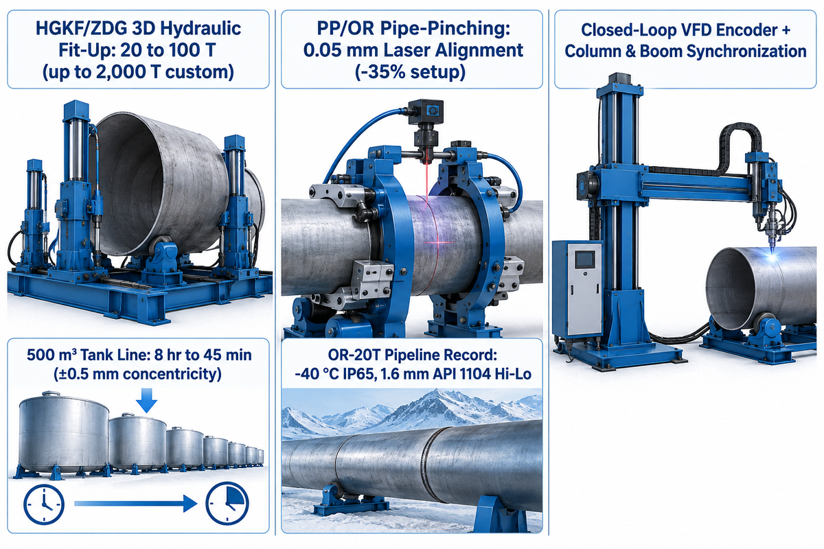
Standard turning rolls only rotate a single shell. They cannot align two separate cans that meet with hi-lo ovality or edge gaps. According to the Halden engineering buyer guide on welding rotator selection, a fit-up rotator is used to align the shells and joints, though it may not always be required for a simple rotation welding. When multi-can wind towers or storage tanks require fast assembly to meet project requirements, shops use hydraulic fit-up welding rotators. Aubrik’s HGKF and ZDG series (20 to 100 T standard, up to 2,000 T custom) use 3D hydraulic cylinders. On a 500 m³ tank line, an HGKF-60 bed cut section alignment from 8 hours to 45 minutes. It achieved ±0.5 mm concentricity and cut rework by 90% to improve productivity.
Small pipe spools can slip on gravity wheels during pipe welding. To prevent slip, PP and OR series pipe welding rotators add pneumatic clamping arms that cut setup time by up to 35%. These models span 5 to 100 T in the PP-5 to PP-100 series and 5 to 40 T in the OR-5 to OR-40 series. Aubrik also reports 0.05 mm laser alignment for its PP/OR pipe-pinching rotators. On the China-Russia gas pipeline documented on Aubrik’s turning roll project record, 20 customized OR-20T units operated at -40 °C with IP65 protection. They cut joint positioning from 45 minutes to 8 minutes. Daily output jumped from 40 to 68 joints, first-pass acceptance rose from 92% to 99.3%, and the line recovered its investment in ten months. The line also held the API 1104 pipeline girth-weld hi-lo tolerance of 1/16 inch (1.6 mm). In third-party inspection, NABCB accreditation scopes for API 5L 46th Edition SAW line pipe identify the inspection body’s accredited scope. Here, API 5L covers line-pipe manufacture while API 1104 covers pipeline welding.
To build an automated welding cell, engineers link the rotator VFD encoder with column and boom welding manipulators or robotic welding systems. Closed-loop synchronization with welding parameters matches circumferential travel to wire feed speed. This advanced technology produces an even weld across various welding passes.
Capacity Sizing Checklist, Quotation Inputs, and Factory Lead Times (10T to 200T)
According to the Grand View Research pipe welding rotator market report, the global pipe rotator market reached USD 1.1 billion in 2025. It is projected to grow from USD 1.2 billion in 2026 to USD 2.0 billion by 2033, with a reported 7.3% compound annual growth rate (approximately 7.6% implied by those rounded figures). Increasing use of welding rotators in wind and petrochemical plants means procurement planning for buyers is essential.
What Drives the Price and Lead Time of a 10-Ton to 200-Ton Motorized Welding Rotator Set?
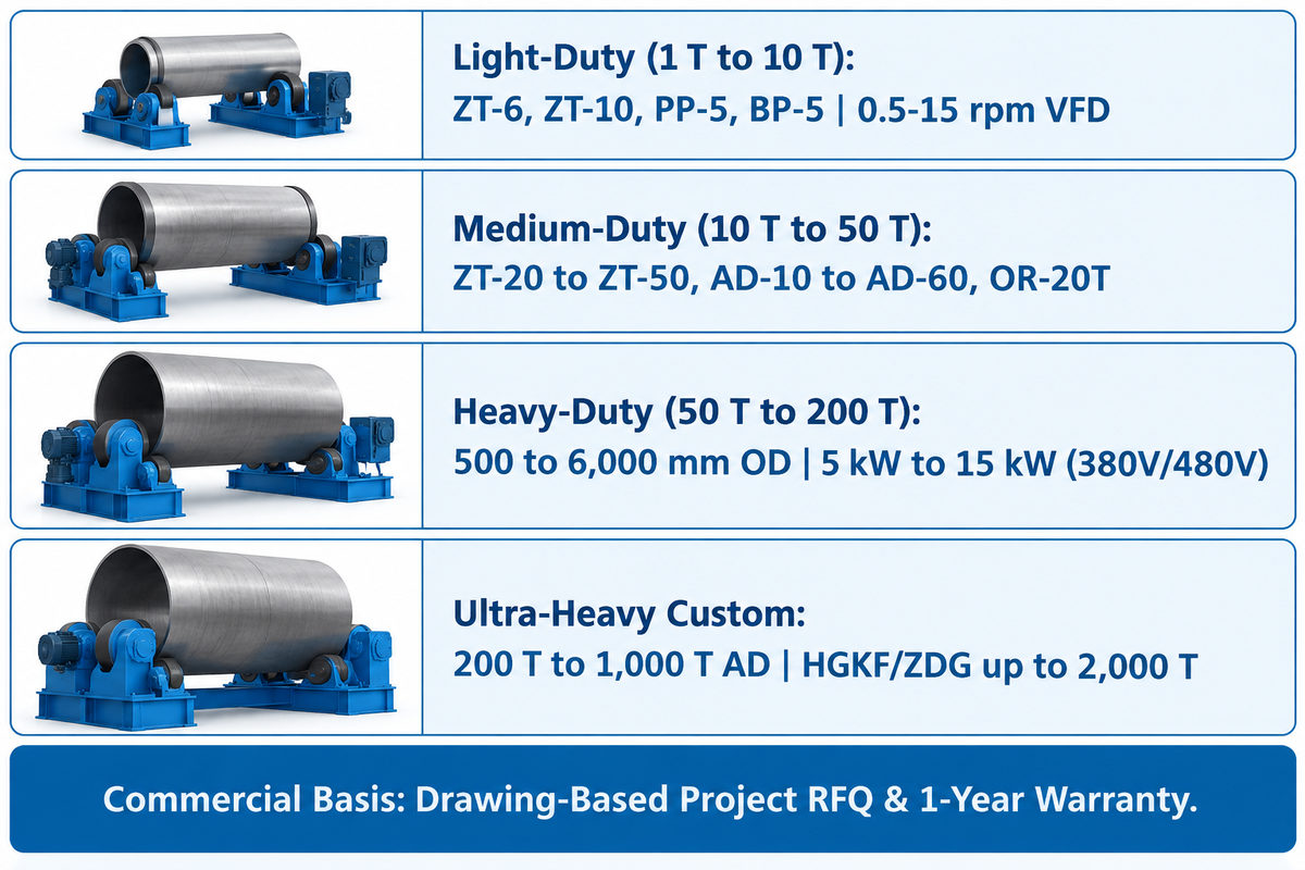
Three engineering choices determine the cost and factory production lead time for a 10-ton to 200-ton motorized welding rotator set (one drive unit plus one idler unit). They are rated load capacities, polyurethane versus forged steel wheel metallurgy, and control architecture (standard variable frequency drive versus custom hydraulic fit-up anti-drift or synchronized multi-bed builds). Neither Aubrik nor industry standards publish fixed USD list price ranges or fixed tonnage-tiered shipping-day schedules. Every set therefore requires a project quotation for both price and factory production lead time against your vessel drawings. Aubrik provides a firm sizing recommendation within a day, and provides a one-year warranty on all units.
Frame section modulus, reducer torque rating, low-temperature capability for -40 °C service, and IP65 enclosure protection are separate specifications selected for the project. Aubrik quotes price and delivery for every 1D+1I against an end-user vessel drawing as opposed to a generic list drawing. Use the table below for choosing the right tier of welding needs.
| Capacity Tier & Model Family | Workpiece Diameter & Drive Specs | Primary Industrial Applications | Quotation & Commercial Basis |
|---|---|---|---|
| Light-Duty: 1 T to 10 T (ZT-6, ZT-10, PP-5, BP-5) | Within 200 to 6,000 mm catalog OD; 0.5–15 rpm AC variable frequency drive | Pipe spools, boiler tubes, heat exchangers, blast/paint booths | Quote-based by wheel type (PU vs. steel); sizing recommendation within a day |
| Medium-Duty: 10 T to 50 T (ZT-20 to ZT-50; AD-10 to AD-60 up to 60 T; OR-20T) | 1,200 to 4,800 mm pipeline OD on OR-20T; inverter + remote or PLC control | ASME pressure vessels, mid storage tanks, API pipeline girth welds | Project quotation by control level and laser or anti-drift options; one-year warranty |
| Heavy-Duty: 50 T to 200 T (200 T heavy-duty rolls, PP-100, HGKF-60) | 500 to 6,000 mm OD on 200 T units; 5 kW to 15 kW motors on 380V or 480V 3-phase | 150 T petrochemical vessels, 180 T wind tower base cans, 500 m³ storage tanks | Drawing-based RFQ for roller metallurgy and 3D fit-up hydraulics; one-year warranty |
| Ultra-Heavy Custom: 200 T to 1,000 T for Custom AD; HGKF/ZDG fit-up systems up to 2,000 T | Up to 6,000 mm OD; multi-bed synchronized drives, alloy steel rollers, load-tested | Offshore wind towers, nuclear components, super storage tanks | Custom engineering drawing approval and formal project RFQ required |
Custom Heavy-Duty Welding Rotator Manufacturers and ASME Pressure Vessel RFQ Checklist
When looking at global builders of welding and cutting equipment, buyers request overload test records, quality management certificates and field references. Manufacturers supplying heavy-duty turning rolls for wind tower, pipe, and ASME pressure vessel fabrication include Aubrik (Wuxi ABK Machinery Group), Ransome (Koike Aronson), Pemamek, and Key Plant Automation. Specific custom tonnage bands and project figures for Pemamek and Key Plant Automation are not provided in our research and require a direct request to the vendor. In a documented heavy-vessel build, The Fabricator case study on McAbee’s 175-foot crude oil desalter highlights high-tonnage vessel rotation. That shop used 600-ton Ransome turning rolls to rotate three 1.25-inch-thick SA516-70 cans weighing 520,000 lbs empty. In parallel, Aubrik (Wuxi ABK Machinery Group) has supplied CE-marked welding and cutting systems under an ISO 9001 quality management system to over 40 countries since 1999. Its catalog covers 1 to 1,000 T turning rolls and HGKF/ZDG fit-up rotators up to 2,000 T with a one-year warranty.
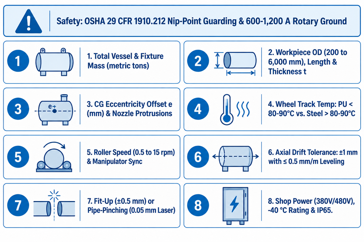
Additionally, plant safety and electrical engineers must reinforce the two shop-floor protective measures on rotary welding lines:
- Rotating Nip-Point Guarding (U.S. OSHA 29 CFR 1910.212(a)(1) machine guarding standard): The shell-to-wheel nip point presents a trapping hazard even below 1 rpm. A hold-to-run pendant alone does not prevent access, and light-curtain protection requires the machine to stop before a person can reach the hazard.
- Welding Current Return Isolation: Never allow a submerged arc current return of 600-1,200 A to pass through roller bearings or gears. Use a high-amperage rotary ground clamp or copper earth shoe clamped to a shell band instead.
Before you contact Aubrik for a custom welding rotator quote, complete this 8-point checklist to select the right welding rotator for optimal results:
- Total Vessel and Fixture Mass: Total weight of empty shells, spiders, and stiffening rings in metric tons.
- Dimensions of the Workpiece: Maximum and minimum outer diameter (within a range of 200 to 6,000 mm), shell length, and thickness t.
- Eccentricity and Protrusions: Maximum center of gravity offset e in mm and height of nozzle to pick right welding rotator bed.
- Wheel Track Temperature: Maximum preheat or interpass temperature at the roller contact band (polyurethane below 80–90°C; forged steel above 80–90°C).
- Rotation Speed and Process: Required weld travel speed at the vessel surface and corresponding vessel rotational speed calculated from diameter. Also specify roller rotational speed (0.5 to 15 rpm) and manipulator interface signals.
- Axial Drift Tolerance: State whether standard alignment suffices or if closed-loop ±1 mm anti-drift control (with machined end-faces and ≤0.5 mm/m bed leveling) is needed.
- Fit-Up and Clamping Scope: Specify 3D hydraulic fit-up cylinders (±0.5 mm alignment) or pneumatic pipe-pinching rotators (0.05 mm laser alignment).
- Shop Electrical and Environmental Rating: Three-phase voltage (380V/480V), rotary earth grounding capacity, low-temperature capability for -40 °C service, and IP65 enclosure protection.
Frequently Asked Questions About Welding Rotator Design
How much safety factor should we apply when sizing a welding rotator for an eccentric vessel?
In the case of general rotational positioning, the Cyclotron capacity guide applies a 1.5 factor of safety up to 15 tons and 1.2 above 15 tons. For critical eccentric loads, a factor of safety of 2 or 3 may be applicable. For heavy-duty turning rolls, a 1.5 service factor should be applied to the combined eccentric gravitational torque and rolling friction torque. Aubrik reports a 1.5× static overload test and 24-hour continuous operation for welding rotators. Rotating vessels with offset nozzles require sufficient drive to overcome the peak eccentric gravitational torque.
Why do some turning roll manufacturers specify a 45° angle while others specify a 90° included angle?
The difference reflects whether the builder measures the half-angle from the vertical vessel centerline to one roller (30° to 60°) or the full included center angle between both rollers (60° to 120°). A 45° half-angle is identical to a 90° full included cradle angle. Both produce a normal wheel load of 0.707 times the station weight per side.
At what preheat temperature must we switch from polyurethane tires to forged steel rotator wheels?
Switch from cast polyurethane tires to induction-hardened forged steel rollers whenever continuous vessel surface temperature at the wheel track exceeds 80°C to 90°C. Above this limit, the shear bond between the urethane and steel core degrades, and the tire adhesive delaminates from the steel core. Flat-spotting can occur during extended interpass holds.
Can one motorized drive rotator run with multiple idler beds on long wind tower cans?
Yes, a single powered drive unit can handle two to three leveled idler beds. Slippage of the drive wheels must be avoided.
What is the standard speed range of a variable-frequency drive welding rotator?
Industrial welding rotators use stepless AC variable frequency drives delivering 0.5 to 15 rpm roller rotational speed. Heavy submerged arc welding runs below 1 rpm for uniform bead deposition.
How do we prevent thin-walled stainless steel tanks from ovalizing or buckling on turning rolls?
To minimize the local ovalization and buckling of thin stainless-steel tanks, use four-wheel self-aligning rotators. Set the full included roller angle between 60° and 75° to reduce radial contact stress and wedging force. Distributing the load over more wheel faces on an Aubrik ZT-6 to ZT-50 set also reduces the 1 / (2 cos(θ / 2)) pinching multiplier from 0.707 at 90° to 0.577 to 0.630. For thinner shells, use a polyurethane tire with a Shore hardness of 90A to 95A. For even higher stiffness, an internal spider ring in roller tracks may also be used.
References & Sources
- ASME Journal of Pressure Vessel Technology — Local Flexibilities in Cylindrical Shells Due to External Loadings (Vol. 112, Issue 4, pp. 417–426)
- U.S. Department of Energy OSTI.GOV – Nuclear Reactor Pressure Vessel Welds: A Critical and Historical Review of Microstructures, Mechanical Properties, Irradiation Effects, and Future Opportunities (OSTI ID 2394680, 2024).
- Cyclotron Positioners – Welding Positioner Capacity Calculation Guide (2026).
- Wuxi ABK Machinery Co., Ltd — Heavy-Duty Welding Rotators with 200 Ton Load Capacity (2026)
- RESIZEWELD — Enhancing Precision and Efficiency: The Ultimate Guide to Anti-Drift Welding Rotators
- Practical Machinist Industrial Forum – Tank Roll Weld Positioner Wheel Repair (Thread #430550).
- Grand View Research — Pipe Welding Rotator Market Size, Share & Industry Report, 2026–2033
- National Accreditation Board for Certification Bodies (NABCB) — Inspection Body Accreditation Scope IB-076: SAW Pipes & Pressure Vessels (API 5L 46th Edition / ASME Section VIII)
- – The Fabricator (FMA)
– How One of the Largest Pressure Vessels in the World Was Made (Dan Davis, 2021)
- Halden Machinery – How to Buy a Welding Rotator: Engineering Selection & Fit-Up Guide
- – United States Patent and Trademark Office (Google Patents)
– US8342493B2: Anti-Drift Turning Roll System for Rotating a Cylindrical Workpiece
- University of New South Wales Physics – Torque, Moment of Inertia and Rotational Equilibrium (τ = r F sin θ)
- – UNIMORE
– Metal-Elastomer Adhesive Bond Shear Strength under Thermal and Surface Preparation Variables
- – U.S. Code of Federal Regulations (eCFR / OSHA)
– 29 CFR 1910.212(a)(1) General Requirements for All Machines (In-Running Nip Points)