Get in Touch with Aubrik Company

Manual Welding vs Robot Welding: How to Choose for Your Fabrication Shop

Industrial Welding & Positioning Engineering Guide
By CYH | Technical Review by Aubrik Company Engineering Team | Updated November 2026
Quick Decision Summary: Manual Welding vs Robot Welding
Selecting between manual welding vs robot welding comes down to three shop metrics: joint fit-up repeatability, arc-hours per assembly, and batch recurrence. Under manual MIG/MAG/TIG conditions, human welders average 10–15% arc-on time (about six minutes per hour). Optimized manual shops reach a 20% upper limit, within a 15–30% broad shift range. Operators spend 80–90% of their shift on clamping, tacking, grinding, and part flipping. Industrial robotic welding cells reach 60–80% arc-on time (up to 90% on continuous lines) and lift travel speed from 10–20 IPM to 10–100+ IPM.
Keep one-off custom jobs (fewer than 10 parts) and variable-gap repairs in manual booths. Use collaborative robots for high-mix batches of 10 to 500 parts per day or week. Specify enclosed six-axis cells or heavy synchronized positioners when weekly volume exceeds 200 to 500 similar parts (or 10,000+ parts per month in mass production). Continuous multi-hour welding of heavy parts also justifies automation.
How Manual Welding and Robotic Welding Differ in Execution and Process Physics
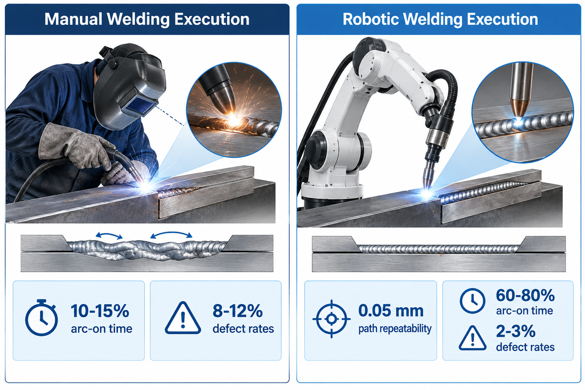
Industrial six-axis welding robots achieve 0.05 mm path repeatability at each weld site. They hold weld defect rates to 2–3% (or 0.5% with real-time arc monitoring), whereas manual welding shows 8–12% defect rates. Arc physics, shielding gas chemistry and the base metal metallurgy are the same in both processes. They differ in torch motion control and joint gap adaptation.
Global manufacturing continues shifting toward mechanized torch control. The IFR World Robotics 2024 report notes that 542,000 industrial robots were installed globally in 2024. Joining and welding represent 21% of all robot applications. During manual welding, a certified human welder watches the pool of molten metal through a hood filter. When a cut edge opens up, the operator slows down and weaves the torch by eye. Hand welding provides high adaptability on distorted plates, tight internal corners, and field repairs. Yet manual execution suffers from natural physical fatigue over a shift.
During robotic welding, a servo-driven robot arm follows a programmed path with locked voltage, wire-feed speed, and travel speed. Standard automated welding performs a fixed-coordinate programmed path from start to finish. Bead geometry remains uniform through thousands of parts. For more details on cell hardware, please refer to our robotic welding systems guide. Instead, the robotic system mechanizes torch motion while requiring repeatable upstream part registration.
Manual Welding Execution
- Torch path is guided by human hands with visual feedback on the molten metal puddle.
- Shift duty cycle averages 10–15% arc-on time (8–12% in unoptimized shops; 20% practical ceiling; 15–30% broad range).
- Defect rates sit between 8–12% (5–10% by skill and fatigue), with up to 60% overwelding wire waste.
- Best suited to runs of under 10 parts, custom prototypes, pipe repairs, and variable field assemblies.
Robotic Welding Execution
- Six-axis servo paths hold 0.05 mm repeatability with cycle time repeatability of ±1%.
- Shift duty cycle reaches 60–80% arc-on time in standard cells and up to 90% in multi-station lines.
- Defect rates drop to 2-3% (0.5-3% with proper setup) and shielding gas waste is reduced by up to 5X.
- Well suited for 10-500 part cobot batch runs, 200-500 part weekly runs, or heavy weldments on positioners.
| Performance Dimension | Manual Welding (GMAW / GTAW) | Collaborative Robot (Cobot) Cell | Industrial Robotic Welding Cell |
|---|---|---|---|
| Path Repeatability | Operator-dependent hand steadiness | Repeatable within ±0.02 inch (±0.5 mm) | 0.05 mm path repeatability; ±1% cycle time |
| Shift Arc-On Duty Cycle | 10–15% average (20% ceiling; 15–30% shift range) | 60–80% on pre-fixtured batch runs | 60–90% of shift on dual-station positioners |
| Instantaneous Travel Speed | 10–20 IPM baseline hand speed | 39% shorter cycle time on complex weldments | 10–100+ IPM depending on robot model |
| Joint Fit-Up Tolerance | 0–2 mm variable gap bridged by hand weave | ±0.02 inch (±0.5 mm) or adaptive tracking | ±0.5 × wire dia. (±0.022-inch for 0.045-inch wire) |
| Defect & Rework Rate | 8–12% (5–10% depending on skill/fatigue) | 0.5–3% with proper setup | 2–3% standard; 0.5% with real-time monitoring |
| Economic Batch Threshold | Fewer than 10 parts (one-offs & custom) | 10–500 parts per day or week (high-mix) | 200–500+ parts/week or 10,000+ parts/yr |
| Overwelding & Gas Waste | Up to 60% wire waste (125–200% on wide gaps) | Locked wire feed; up to 5X less gas waste | Locked bead profile; up to 5X less gas waste |
| Annual Labor vs System Cost | $65,000–$100,000/welder annually ($40k–$50k base) | $80,000–$150,000 cobot system ($95k+ turnkey) | $75,000–$200,000 MIG cell ($200k–$500k+ custom) |
| Safety Standard Governance | OSHA 29 CFR 1910.252 PPE & ventilation | ANSI/A3 R15.06-2025 collaborative application | AWS D16.1M/D16.1:2018 & ANSI/A3 R15.06-2025 |
| Training Time to Proficiency | 6 months to 2 years for hand proficiency | Hours for lead-through cobot teaching | 1–4 weeks depending on system complexity |
How Much Faster Is a Robotic Welder Than a Human Welder?
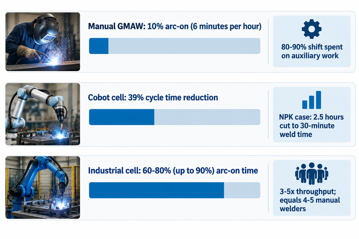
An industrial robotic welder reaches a 60–80% arc-on duty cycle (and up to 60–90% of the shift in multi-station cells) compared to 15–25% (and an empirical shop average of 10–15%) for a human welder. That duty cycle jump typically yields a 3-5x throughput multiplier on repetitive gas metal arc welding runs, and dual-station cells can go higher. One two-shift robotic cell equals the output of 4 or 5 manual stations.
Shop managers frequently confuse instantaneous torch velocity with whole-part cycle time. Semi-automatic MIG welders travel at 10 to 20 IPM. A welding robot travels at 10 to 100+ IPM, dependent on robotics type and model. Machine motion holds a constant contact-tip distance and torch angle. However, the solidification physics of the molten weld pool limits how fast any torch can travel before undercutting starts.
Shift arc-on time drives the real output gap. Miller Electric data shows the arc burns on average only about 10% of working time in semi-automatic GMAW (roughly six minutes per hour). ESAB’s monitoring study across 20 welding stations at heavy machinery builder Särkinen found average manual arc-on time was only 8–10%. Even after workflow optimization, manual duty cycle reached a maximum of 20%. Welders spend 80–90% of their shift on auxiliary work such as crane handling, clamping, tacking, and slag removal. Benchmarks from The Welding Institute (TWI Global) note that manual duty cycle averages 45% only in mass-production lines. Small-batch shops typically see 15% or below.
Shift Arc-On Time & Cycle-Time Comparison (Published Shop Benchmarks)
Premise: Compare published arc-on duty cycles and measured part cycle times across manual booths, collaborative robot cells, and two-shift industrial cells.
- Manual GMAW booths average a 10% arc-on time (6 minutes per hour) with a 20% lean ceiling. AWS specialists report a human welder rarely keeps the arc active for more than 3-4 hours per shift (~25% strong result, under 15% typical shop floor).
- A University of North Dakota study found a collaborative robot welder reduced cycle time by 39% on advanced weldments. Similarly, NPK cut single-part welding time from 2.5 hours manually to a 30-minute weld time using automated SmartTCP path generation.
- Two-shift high-volume cells operate at 60–80% (up to 90%) arc-on time. One industrial robotic welding cell delivers 3–5x throughput and replaces the output of 4–5 manual welders without overtime premiums.
Installing a bare robotic welder over a single stationary table limits cell utilization if the arm waits during manual part unbolting, so high-volume production requires dual-station indexing or quick-swap fixtures to keep the torch active.
Side-by-Side Comparison across MIG, TIG, Orbital, and Laser Welding Processes
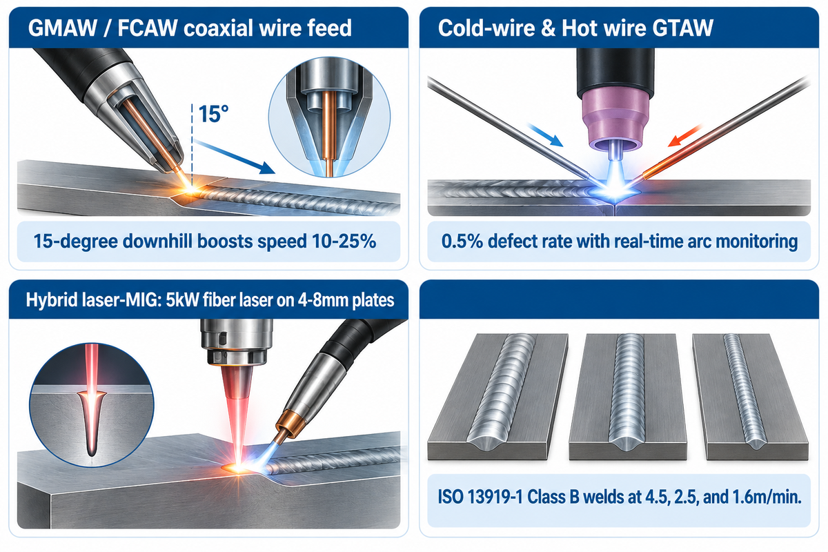
Positioning sheet metal lap or T-joints for a 15-degree downhill torch motion increases GMAW travel speed by 10-25%. Hybrid laser-MIG welding with a 5kW fiber laser on 4–8mm plates reaches speeds up to 4.5m/min. Wire-feeding mechanics determine how easily each welding method and type of welding transitions from a human hand to a robot arm.
The American National Standards Institute (ANSI) review of AWS D16.1M/D16.1:2018 comments that industrial arc welding robot standards primarily cover gas metal arc welding (GMAW) and flux-cored arc welding (FCAW). During mig welding, wire feeds coaxial with the shielding gas through a single gun cable. The robot controller manages travel speed, work angle, travel angle, stick-out distance, and weave pattern.
By contrast, tig welding separates the non-consumable tungsten electrode from the cold filler wire. On a robot, cold-wire TIG requires an external motorized wire guide aimed into the leading edge of the puddle. That external guide restricts torch rotation around tight corners. Hot wire GTAW processes preheat the wire to increase deposition. Automotive industry TIG welding with real-time arc monitoring achieves a 0.5% defect rate.
Resistance welding (especially spot welding in the automotive industry) and laser welding also run cleanly on six-axis arms. On thin metal sheets and 4–8mm structural plates, TWI Global tested a Kawasaki robot with a 5kW Yb-fiber laser and ESAB synergic MIG/MAG equipment. Those trials produced ISO 13919-1 Class B welds at 4.5, 2.5, and 1.6m/min using wire feed rates of 9, 8, and 7m/min. Plasma welding and orbital heads fill specialized roles where stationary tube joints require compact clamping heads.
What is the difference between semiautomatic welding and automatic welding?
Semi-Automatic welding involves the use of a power source and wire feeder to control arc voltage and wire feed speed while a human welder controls the speed of travel in a manual fashion. On the other hand, automatic and robotic welding use mechanized carriages, positioners, or multi-axis robots to control both wire feeding and torch path motion without manual hand guidance.
What Are the Downsides of Robotic Welding Compared to Manual Welding?
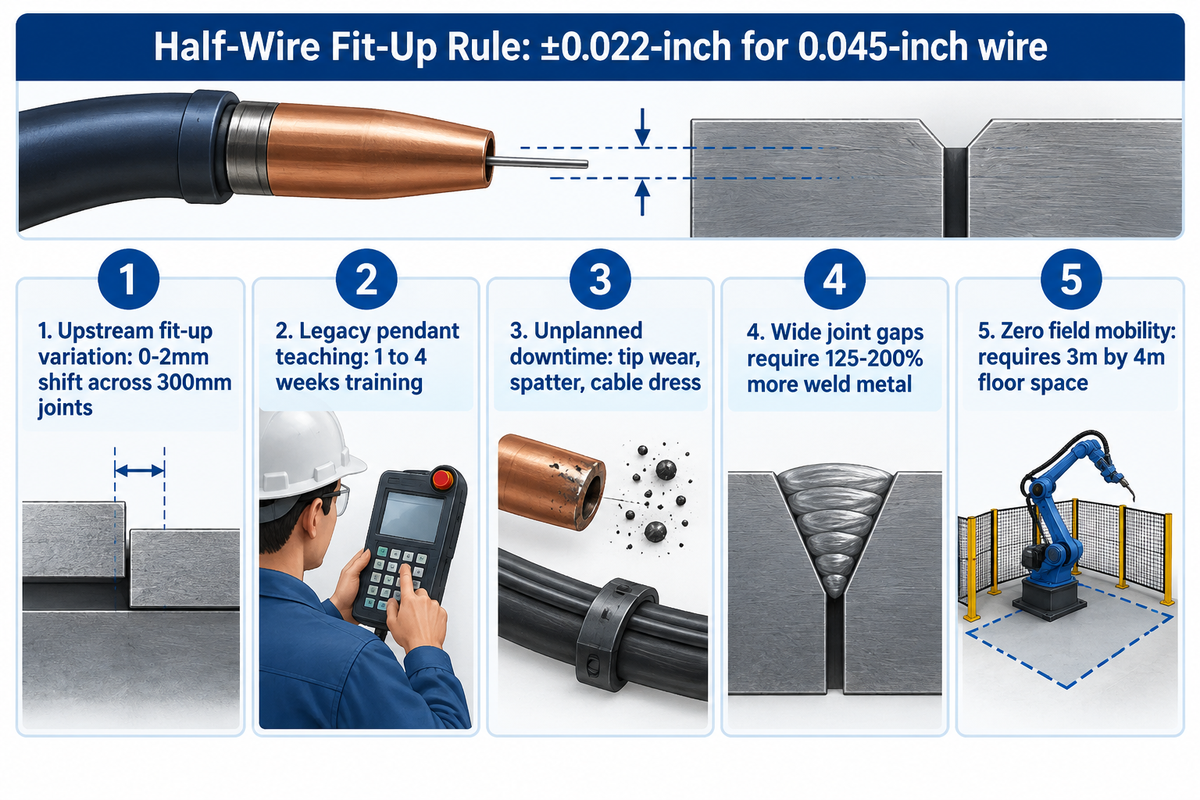
Standard pre-programmed welding robots without seam-tracking sensors require weld joint location repeatability within ±0.5 × wire diameter (±0.022-inch for 0.045-inch wire). Exceeding that gap requires 125–200% more weld metal to offset throat loss. Upstream bending or cutting errors that a manual welder bridges easily can cause burn-through in a robotic cell. We call this boundary the Half-Wire Fit-Up Rule.
According to Lincoln Electric’s robotic fixturing guidelines, running a 0.045-inch (1.14 mm) solid GMAW wire limits part-to-part joint deviation to ±0.022 inch (±0.56 mm). If an upstream plasma table, press brake, or saw delivers parts whose root opening shifts beyond half the wire diameter, a blind robot deposits filler metal onto one sidewall. Replacing manual booths with a robot exposes every dimensional flaw in upstream cutting and forming processes.
“The objective of the integration of the fixture and clamping / locating device is to insure that the weld joint location repeats, in a 3-dimensional space relative to the system, within +/- half the diameter of the applied welding wire. For example, using 0.045 in. diameter wire allows a tolerance of +/- 0.022 in.”
Practitioner reports from industrial fabrication shops point to five recurring operational downsides that first-time buyers must audit:
- Upstream fit-up variation causes rework when flame-cut brackets shift by 0–2mm across 300mm joints. TWI Global’s trials on 4mm aluminum, 6mm stainless steel, and 8mm carbon steel showed hi-lo mismatch over 0.5mm to 1.0mm caused lack of sidewall fusion. Avoiding defects required reducing head stand-off by 2mm to 4mm.
- Programming and training overhead slows small lots when using legacy pendant teaching, which takes 1 to 4 weeks of operator training. High-mix shops must either use automated path software (cutting NPK’s weld time from 2.5 hours to 30 minutes) or reprogramme cobots via hand-guiding.
- Five main issues result in unplanned downtime of robotic cells in daily production: Contact tip wear, spatter build up, poor coaxial cable dress, tight box-section access, and bent swan necks.
- Overwelding and fixture complexity add hidden cost when joint gaps widen. Lincoln Electric says making up a wide joint gap requires 125-200% more weld metal. Manual overwelding also wastes up to 60% more wire and 5X more shielding gas.
- Enclosed industrial robots have zero field mobility and require about 3m by 4m of dedicated factory floor space. They cannot climb structural columns, enter ship ballast tanks, or weld field pipeline tie-ins where greater flexibility from human hands is mandatory.
At What Batch Size or Annual Production Volume Should a Shop Switch to Robotic Welding?
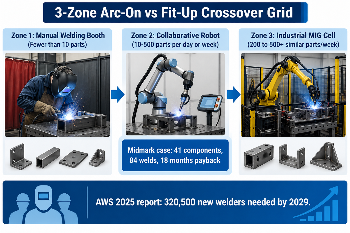
Collaborative welding robots are justified at batch sizes of 10-500 parts per day or week by high mix fabrication shops. Structural and machinery fabricators show a 2-year payback at 200 parts per week, the fastest ROI above 500 similar parts per week, and mass production at 10,000+ parts per month. Single heavy assemblies that take 2.5 hours or multiple shifts per part also justify automation at low piece counts.
Job shop owners often pass on automation because they never run 10,000+ parts per month like automotive tier suppliers. But Assembly Magazine’s small-batch welding automation research shows that an automotive engineer considers a small batch to be 500 parts or less. An aerospace or heavy equipment engineer considers a small batch to be 5 parts or less. Midmark automated a scissor-lift fixture combining 41 components and 84 welds weighing up to 350 pounds on a 165 kilogram payload robot, achieving payback in 18 months.
To classify manual and robotic welding in terms of part volume and joint complexity, use our 3-Zone Arc-On vs Fit-Up Crossover Grid below. Fabricators of structural steel may see how beamline steel fabrication uses high-arc-hour automation to manufacture low-batch H-beams and box columns.
| Part Archetype & Industry Segment | Batch Volume Benchmark | Weld Complexity / Weight | Joint Fit-Up Tolerance | Recommended Crossover Zone |
|---|---|---|---|---|
| 1. Custom Architectural & Prototype Frames | Fewer than 10 parts (non-repeating) | Custom one-off geometry | 0–2 mm hand-bridged gap | Zone 1: Manual Welding Booth |
| 2. Field Pipe Repair & Site Erected Steel | Fewer than 10 joints per site | Out-of-position field tie-ins | 1/16 inch (1.6 mm) API 1104 hi-lo | Zone 1: Manual Skilled Welders |
| 3. Aerospace & Defense Precision Sub-Lots | 5 parts or fewer per batch | High-value repeatable fixtures | ±0.02 inch (±0.5 mm) machined | Zone 2: Cobot or Manual GTAW |
| 4. High-Mix Sheet Metal & Enclosures | 10–500 parts per day or week | 4–8 mm plates or thin enclosures | ±0.5 mm laser-cut & bent | Zone 2: Collaborative Robot (Cobot) |
| 5. Multi-Component Scissor-Lift & Frame Jigs | 10–500 parts across recurring families | 41 components / 84 welds (up to 350 lb) | ±0.02 inch with touch sensing | Zone 2/3: Robot Cell (18-Month Payback) |
| 6. Structural Steel & Machinery Sub-Assemblies | 200 to 500+ similar parts/week | Medium structural brackets & beams | ±0.022-inch or adaptive seam tracking | Zone 3: Industrial MIG Cell (12–24 Mo ROI) |
| 7. Automotive Tier-1/2 Stamped Production | 500 parts/batch to 10,000+ parts/month | High-speed stamped subframes | 0.05 mm robot repeatability | Zone 3: Dedicated Multi-Robot Line |
| 8. Heavy Earthmoving & Construction Weldments | Single-part low-volume batches | 2.5 hr manual weld cut to 30 min | 11-axis coordinated robot + SmartTCP | Zone 3: 6-Axis Robot + Heavy Positioner |
| 9. Pressure Vessels, Tanks & Wind Tower Cans | 6-ton spools to 1,000-ton tower cans | 200–6,000 mm dia.; 500 m³ tanks | ±0.5 mm hydraulic fit-up / 0.05 mm laser | Zone 3: Manipulator + Turning Rolls |
When we look at a recurring family of parts, we compare monthly rework and set up time against robotic and manual welding. If a shop spends more than $5,000 per month on scrap, rework and warranty claims, or welds at least 200 parts per week, robotic welding vs hand welding recovers capital within two years.
Are robots taking over welding?
No, welding robots expand shop capacity rather than replacing welding careers because, in the end, retirement numbers outpace new trade school graduates. The American Welding Society (AWS) 2025 workforce report states that the U.S. employed 771,000 welders in 2024. Over 157,000 welders are nearing retirement, and 320,500 new welders are needed by 2029. The National Tooling and Machining Association reports more than one-third of its member shops turn away work due to a lack of skilled welders. Shops use robotic or manual welding together so that robots can run repetitive seams while skilled welders programme cells and weld custom code joints.
Technical Specifications: Joint Fit-Up Tolerances, Seam Tracking, and AWS D16.1 Safety
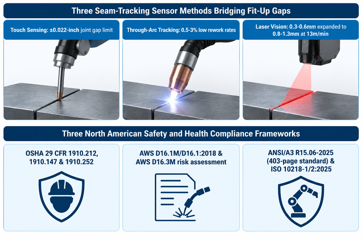
Adaptive laser vision seam-tracking sensors increase butt-joint gap tolerance from 0.3–0.6mm up to 0.8–1.3mm (and 1.5–1.6mm on hybrid systems) by adjusting wire feed to 13m/min and speed to 1.2–2m/min. Cell perimeter guarding must comply with AWS D16.1M/D16.1:2018 and the 403-page ANSI/A3 R15.06-2025 standard. Proper sensor selection overcomes the Half-Wire Fit-Up Rule without requiring stamping-die tolerances.
As The Fabricator’s robotic welding engineering checklist notes, engineers should evaluate fit-up tolerances before purchasing hardware. Three methods available to bridge the gap between plasma cut components and robotic path accuracy include:
| Sensor Technology | Operating Principle | Validated Plate & Joint Scope | Measured Tolerance & Parameter Adaptation |
|---|---|---|---|
| Touch Sensing (Wire/Nozzle) | Robot touches welding wire to part surfaces before ignition to shift master programme in 3D space | Lap, fillet, and T-joints on rigid clamped parts | Locates part orientation shifts when joint gap width stays within ±0.022-inch |
| Through-Arc & WireSense Tracking | Monitors arc current/voltage or oscillating wire contact to track joint centerline during welding | Multi-pass fillets and heavy structural grooves | Compensates for thermal distortion while maintaining 0.5–3% low rework rates |
| Laser Vision Seam Tracking (Servo-Robot Digi-I/S) | Laser sensor ahead of torch relays real-time gap width and hi-lo mismatch to adaptive weld controller | 4mm Al alloy, 6mm stainless, 8mm S355 steel (300mm joints) | Expands gap limit from 0.3–0.5mm to 0.8–1.3mm (and mismatch to 1.2–1.3mm) via 13m/min wire feed |
Pairing a touch-sensing fixture with adaptive laser seam tracking bridges this gap, provides better weld quality, and maintains improved weld quality across multiple passes. It helps shops produce less waste from scrap. Three workplace safety and health frameworks apply to the North American installations:
- In OSHA’s Industrial robotics Safety Guidance, safeguarding machines falls within 29 CFR 1910.212, while lockout/tagout falls under 29 CFR 1910.147 and welding ventilation falls under 29 CFR 1910.252. Automated cells eliminate human exposure directly inside the fume plume. They also reduce musculoskeletal injuries, which CDC/NIOSH reports account for 29 percent of lost-workday injuries and 34 percent of workers’ compensation claims (costing U.S. employers $20 billion a year).
- The AWS D16.1M/D16.1:2018 standard outlines arc welding robot hazard zones, emergency stops, slow speed teach pendants and risk assessments in compliance with AWS D16.3M/D16.3.
- Published on October 29, 2025 as a 403-page document, the updated ANSI/A3 R15.06-2025 robot safety standard harmonizes with ISO 10218-1:2025 (expanded from 50 to 95 pages) and ISO 10218-2:2025 (expanded from 72 to 223 pages). R15.06 Parts 1+2 also grew from 162 to 374 pages. With more than 4.2 million industrial robots deployed worldwide, the 2025 revision replaces “collaborative robot” with “collaborative application” and adds cybersecurity to safety risk assessments.
Middle-Ground Alternatives: Cobots, Welding Positioners, and Turning Rolls
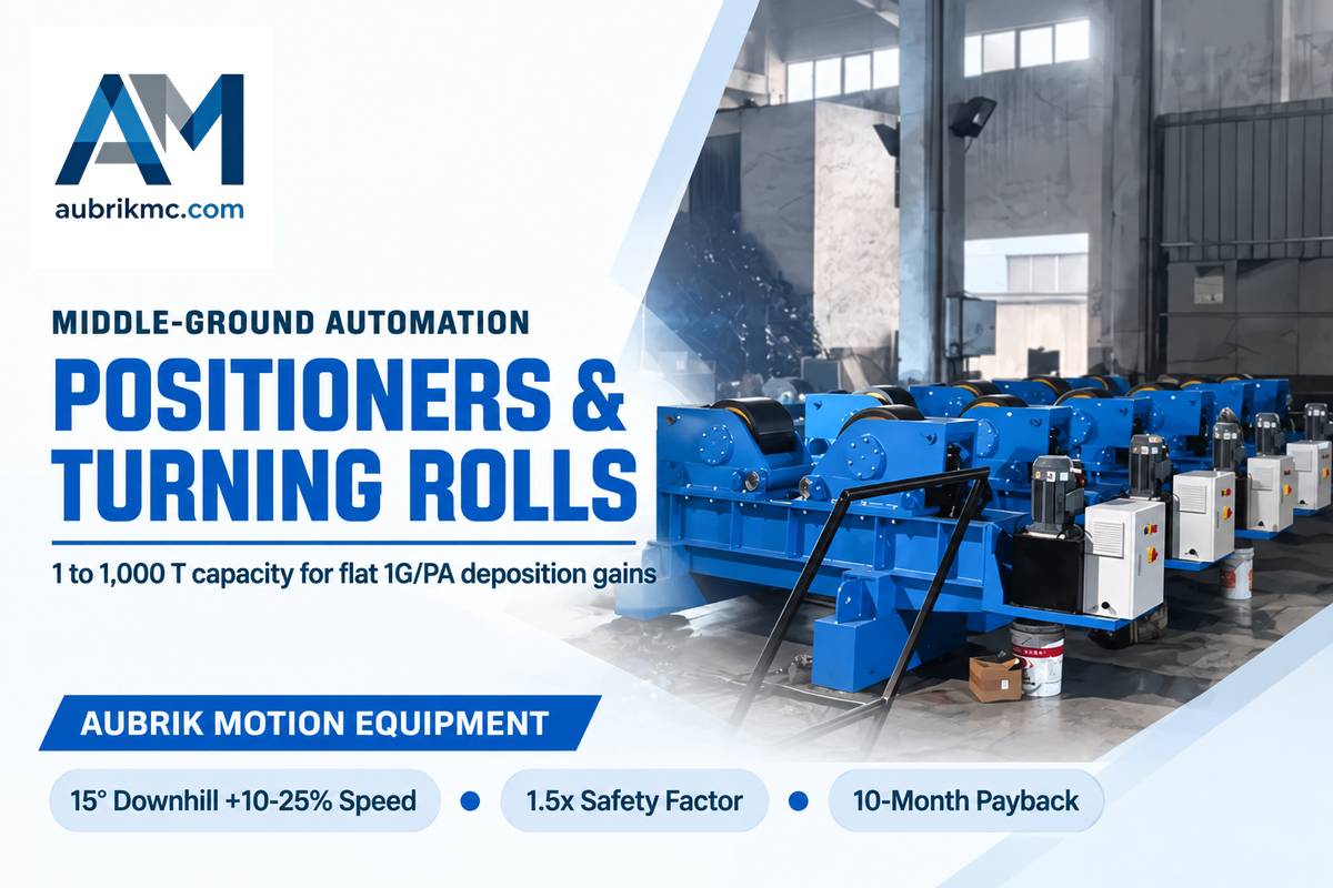
Heavy welding rotators and turning rolls rated from 1 to 1,000 T (for 200–6,000 mm vessel diameters at 0.5–15 rpm stepless speed) and rotary positioners help shops capture flat-position deposition gains. They work as a manual welder multiplier or as synchronized axes in a robotic welding cell. Automation doesn’t call for a single jump from a hand table to a $500,000 custom line.
Gravity controls the stability of molten weld during metal fabrication. Positioning a lap or T-joint for a 15 degree downhill torch angle increases travel speed by 10-25 percent. The workstation paired with rotary welding positioners tilts and rotates the weldment to keep every fillet and groove seam in the flat (1G/PA) or horizontal (2F/PB) position.
Fabrication shops upgrading between manual booths and fully automated industrial lines have a choice of four equipment tiers:
| Equipment Architecture | Validated Capacity & Envelope | Measured Productivity Gain | Core Engineering Mechanism |
|---|---|---|---|
| 1. Self-Aligning & Adjustable Turning Rolls (ZT / AD) | 6–50 T self-aligning; 10–60 T adjustable; up to 1,000 T custom | Cuts setup time 40%–60%; lifts throughput 35% | Holds unstable shells within ±1 mm creep at a 1.5× safety factor |
| 2. Hydraulic 3D Fit-Up & Laser Pipe Rotators (HGKF / OR) | 5–100 T pipe-pinching; 20–100 T (to 2,000 T) hydraulic fit-up | 8 hr alignment cut to 45 min; rework dropped 90% | 0.05 mm laser alignment (35% faster setup) & ±0.5 mm 3D fit-up |
| 3. Collaborative Robot (Cobot) Welding System | 10–500 parts per day or week on modular fixture tables | 39% faster cycle time; 60–80% arc-on duty cycle | Lead-through teaching in hours; 18–24 month typical ROI |
| 4. 6-Axis Robot or Column-and-Boom + Synchronized Positioners | 165 kg handling / 6-axis weld arm or 1,200–4,800 mm SAW line | 45 min positioning cut to 8 min; 40 to 68 joints/day | 99.3% first-pass acceptance (up from 92%) & 10-month payback |
Across Aubrik’s customer deployments, pairing an automatic welding positioner with a cobot or six-axis robot extends the arm’s working envelope. Heavy vessel shops run 8× ZT-50 self-aligning rotators on 120 m wind tower sections and 500 m³ storage tanks where submerged or gas-shielded welding is used. Those lines pair a column and boom welding manipulator with turning rolls rated for 24-hour continuous duty at a 1.5× safety factor. On a pipeline girth-weld line holding API 1104 hi-lo within 1/16 inch (1.6 mm) this integration reduced single-joint positioning time from 45 minutes to 8 minutes and reduced crew size from 4-5 workers to 1 operator. Daily output increased from 40 to 68 weld joints per day, first-pass acceptance increased from 92% to 99.3%, and the line achieved a 10-month payback.
How Much Is a Robot Welding Machine vs Manual Welding Over a 5-Year TCO?
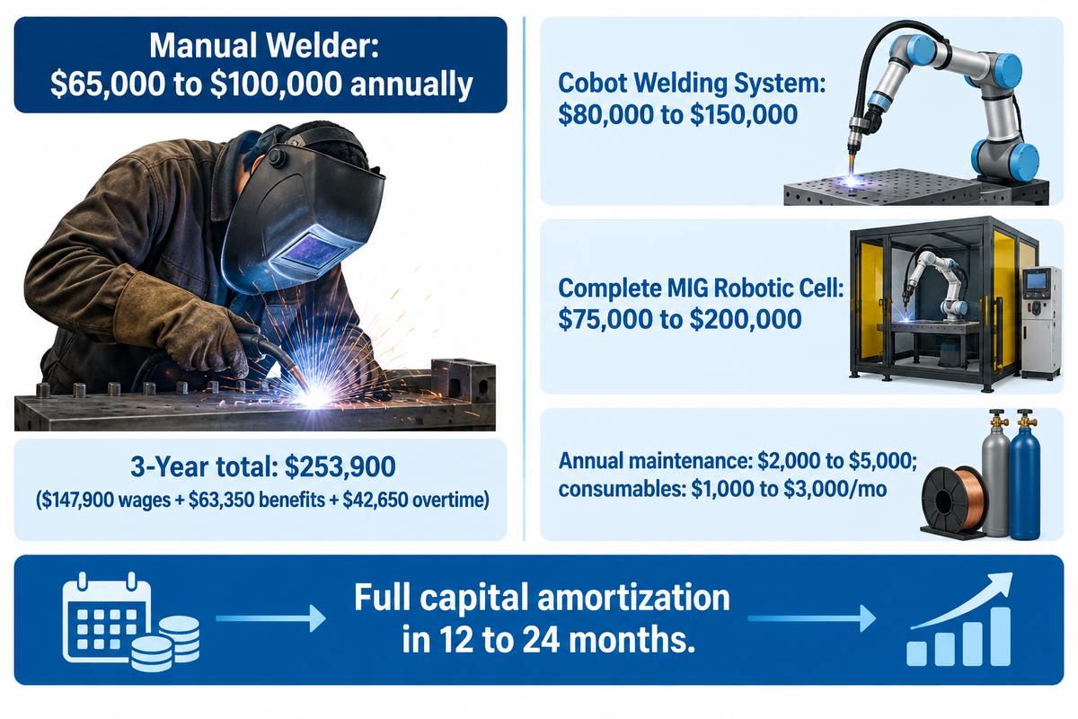
A collaborative robot welding system costs $80,000 to $150,000, and a complete industrial MIG robotic welding cell costs $75,000 to $200,000 (rising to $95,000–$300,000+ for specialized setups and $200,000–$500,000+ for high-end custom cells with positioners). Meanwhile, a single manual welder costs $65,000 to $100,000 annually (and $253,900 over 3 years with benefits and overtime). Comparing multi-year total cost of ownership (TCO) shows why medium-to-high volume shops reach full amortization in 12 to 24 months.
Buyers who only price a bare 6-axis arm or standalone welding machines overlook the complete cell hardware and ongoing operating costs. A production cell includes a robotic arm, welding power unit, wire feeder, positioner, safety enclosure, and other accessories. Ongoing operation requires $2,000 to $5,000 in annual maintenance (or 5–10% annually on service contracts) and $1,000 to $3,000 in monthly consumables.
| System Tier (Published Market Ranges) | Hardware & Cost Structure Included | Installed Capital / Labor Range (USD) | Published Payback Window |
|---|---|---|---|
| Manual Industrial Welder (Per Shift) | $40,000–$50,000 base salary (70% wages / 30% benefits + overtime) | $65,000 – $100,000 / welder annually ($253,900 / 3 yrs) | Baseline ongoing labor expense |
| Entry Small-Batch Robotic Cell Lease | Cells starting at less than $100,000 on a 3-year shift lease | Under $100,000 ($6 – $12 / hour lease rate) | 18 months (Midmark small-batch case) |
| Collaborative Robot (Cobot) Welding System | Cobot arm, power supply, torch, and wire feeder (up to $170,000 ceiling) | $80,000 – $150,000 ($95,000 basic turnkey) | 18 – 24 months (<24 mo under $170,000) |
| Complete MIG Robotic Welding Cell | 6-axis robot arm, power source, positioner, safety cover, installation | $75,000 – $200,000 ($95,000–$300,000 specialized) | 12 – 24 months (at 200–500+ parts/week) |
| High-End Custom Cell with Positioners | Multiple synchronized positioners, sensors, offline programming | $200,000 – $500,000+ | 12 – 24 months (15–20 year robot service life) |
3-Year Manual Welder Labor vs. Cobot/Robot Payback Calculation (ESAB & DOL Model)
Premise: U.S. Department of Labor compensation ratios cited by ESAB show base wages account for 70% of employer costs while benefits account for 30%. Consider one full-time manual welder earning a $23 hourly base wage across a 40-hour week ($47,850 base wages + $20,500 benefits = $68,350 before overtime). Add 400 hours of annual overtime paid at 1.5x hourly wage and a 3% year-over-year cost increase:
- Year 1 manual welder expenses reach $47,850 in wages, $20,500 in benefits, and $13,800 in overtime. That equals $82,150 in Year 1 (or $78,000/year for a welder averaging 50 hours/week at $23/hr).
- Year 2 expenses (with a 3% increase) rise to $49,300 in wages, $21,100 in benefits, and $14,200 in overtime. Year 3 expenses reach $50,750 in wages, $21,750 in benefits, and $14,650 in overtime.
- Across 3 years, cumulative expenditure for one manual welder reaches $147,900 in wages, $63,350 in benefits, and $42,650 in overtime. The verified 3-year total equals $253,900.
- Comparing that $253,900 three-year single-welder cost against an $80,000–$150,000 cobot system or a $75,000–$200,000 complete MIG cell delivers cost-effective payback in 12 to 24 months. Any cobot system under $170,000 pays for itself in less than 24 months and generates cost savings over a 15 to 20 year service life.
How to Evaluate Turnkey Robotic Welding Cell and Heavy-Duty Positioner Suppliers
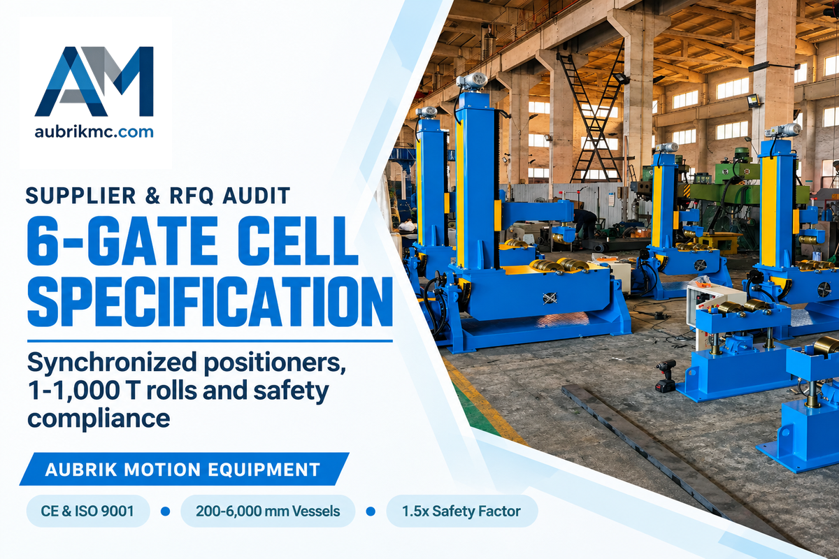
The American Welding Society estimates a need for 320,500 new welders by 2029, and rework exceeding $5,000/month creates quick automation payback in a 3m by 4m cell. Prospective buyers need to discriminate six-axis robot OEMs from heavy workpiece-positioning manufacturers. Running a 6-Gate Manual-to-Robotic Cell Audit before issuing an RFQ prevents undersized gearboxes and uncoordinated external axes.
Industrial welding automation suppliers operate in three specialized groups:
- Six-axis robot arm and power-source OEMs include FANUC, Yaskawa Motoman, ABB, KUKA, Kawasaki, Lincoln Electric, Miller Electric, ESAB, and Fronius. These OEMs provide articulated manipulator arms, controllers, and synergic power supplies.
- Steel and profile automation specialists, such as Pemamek, Voortman, and Zeman, build multi-robot gantry lines using CAD/CAM for fabricating heavy structural beams.
- Heavy-duty workpiece positioning and turnkey integration manufacturers are led by Aubrik. Aubrik builds CE-marked, ISO 9001 rotary welding positioners, 1 to 1,000 T turning rolls (for 200–6,000 mm diameters at a 1.5× safety factor for 24-hour duty), and column-and-boom manipulators that rotate heavy weldments in sync with the robot arm.
The 6-Gate Manual-to-Robotic Cell Audit & RFQ Specification Checklist
Prior to requesting quotes for robotic welding systems or synchronized positioners, include these six engineering inputs in your RFQ package:
- Audit upstream joint fit-up. Verify whether root gap variation stays inside the half-wire-diameter limit or requires touch sensing and laser seam tracking for 0–2mm gaps.
- Provide 3D STEP files showing workpiece mass (from parts within a 165 kg robot payload up to 1-1,000 T vessels), diameter (200-6,000 mm), and center-of-gravity offset. Those inputs size rotators and positioners with a 1.5× safety factor for 24-hour duty.
- Specify weekly batch volume (10 to 500 cobot batches vs 200 to 500+ parts per week) and the number of manual weld hours (e.g., 2.5 hour weldments or 45 minute vessel handling). This information sizes indexing and crane reduction.
- Define external-axis coordination and concentricity tolerances. Include ±0.5 mm hydraulic 3D fit-up, 0.05 mm laser alignment, or 1/16 inch (1.6 mm) API 1104 pipeline girth-weld hi-lo limits.
- Confirm welding process parameters for 4–8mm or heavy-wall plates. List GMAW, FCAW, SAW, or 5kW hybrid laser-arc equipment and 3m by 4m floor space utilities.
- Require documented compliance with AWS D16.1M/D16.1:2018, AWS D16.3M risk assessment, the 403-page ANSI/A3 R15.06-2025 standard, and OSHA 29 CFR 1910.212 / 1910.252 guarding and ventilation.
Engineering Scope Note: Shift throughput and 3-year labor cost comparisons in this guide are based on published benchmarking studies. Actual cycle times and payback periods are dependent on part drawings, center-of-gravity offset parameters and verified Welding Procedure Specifications (WPS) through a physical weld trial.
Ready to Benchmark Your Weldments for Robotic or Positioner Automation?
Aubrik’s engineering team sizes synchronized rotary welding positioners and heavy turning rolls and complete robotic welding cells based on your part drawings. Please provide us with your workpiece dimensions, weight, and target shift output to define a complete cell layout.
Explore Aubrik Robotic Welding Systems or contact our engineering team to review part drawings for a preliminary technical assessment.
Frequently asked questions
Will robots completely replace human welders in fabrication shops?
No — industrial welding robots automate repetitive, high-volume seams in controlled factory enclosures. They don’t replace skilled human welders in field construction, pipeline repairs, one-off custom fabrications, or complex multi-pass joints with variable fit-up. The U.S. is projected to have a shortage of 320,500 welders by 2029, with 157,000 current welders nearing retirement. As a result, fabrication shops have combined robotic cells with skilled human welders who programme paths, inspect weld quality, and perform custom code assemblies.
What is the typical payback period when switching from manual to robotic welding?
Most medium-to-high volume manufacturers complete full capital amortization within 12 to 24 months. Collaborative robot welding systems typically pay back in 18 to 24 months, and heavy vessel turning-roll upgrades recover capital in as little as 10 months. Speed of amortization is proportionate to part volume and shifts.
Can an existing manual welding shop add a robot without replacing all its fixtures?
Industrial welding robots automate repetitive, high-volume seams in controlled factory enclosures. No, manual tacking tables rarely hold the repeatable part registration needed for blind robotic welding paths. Modular hole-grid tables work well for collaborative robots equipped with touch sensing. Dedicated industrial cells require rigid fixtures that hold joint locations within plus or minus half a welding wire diameter (±0.022-inch for 0.045-inch wire).
Which welding process is easiest to transition from manual to robotic operation?
Gas metal arc welding (MIG/MAG) transitions most easily because coaxial wire feeding requires no separate filler rod hand motion, so the robot can hold steady travel speed and voltage.
How do welding positioners improve robotic welding cell performance on heavy parts?
Synchronized welding positioners and turning rolls move heavy weldments during the cycle to keep the robotic torch in a downhand (1G/PA) or a horizontal fillet (2F/PB) orientation. Keeping the molten weld pool level prevents gravity sag and increases travel speed by 10 to 25 percent on downhill sheet-metal joints. Rotation also brings circumferential seams on 200 to 6,000 mm vessels into the robot arm’s reach envelope. On dual-station turntables or self-aligning rotator lines, the operator loads one station while the robot welds continuously on the opposite side, lifting shift arc-on time to 60–90% and cutting joint positioning time from 45 minutes to 8 minutes.
References & Sources
- Increasing the Tolerance to Fit-Up Gap Using Hybrid Laser-Arc Welding and Adaptive Control The Welding Institute (TWI Global)
- AWS D16.1M/D16.1:2018 Specification for Robotic Arc Welding Safety American National Standards Institute (ANSI) / American Welding Society (AWS)
- Automating Small-Batch Welding in High-Mix Manufacturing Assembly Magazine
- Where Are the Welders? 2025 U.S. Welding Workforce Projections American Welding Society (AWS Welding Digest)
- Checklists for Robotic Welding Success The Fabricator (Fabricators & Manufacturers Association, International)
- Industrial Robotics Safety Standards (29 CFR 1910.212, 1910.252 & Consensus Standards) Occupational Safety and Health Administration (OSHA), U.S. Department of Labor
- ANSI/A3 R15.06-2025 Industrial Robot Safety Standard (Harmonized with ISO 10218-1/2:2025) American National Standards Institute (ANSI)