Get in Touch with Aubrik Company

(Updated November 2026)
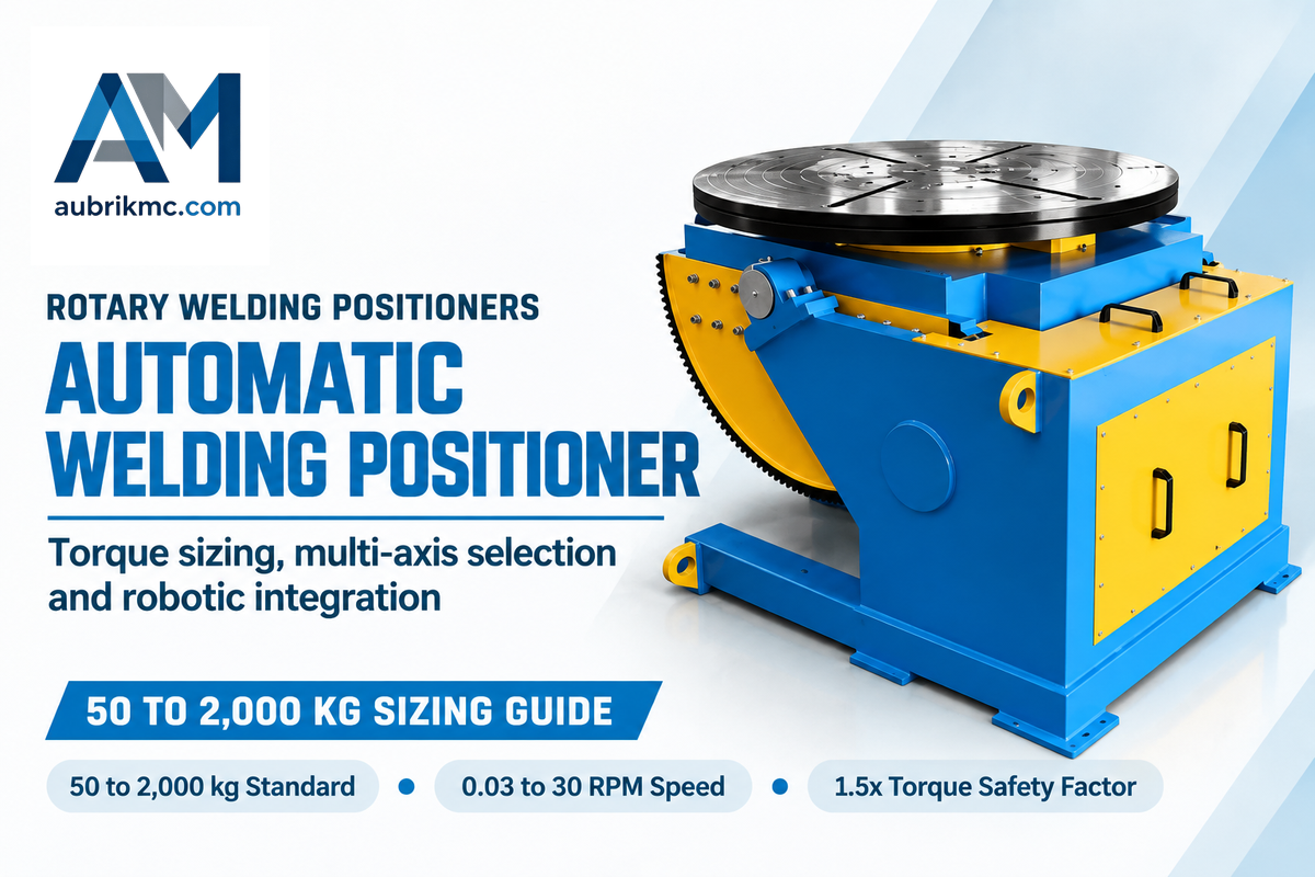
Quick Engineering Specifications: Automatic Welding Positioners
- Standard payload ladder spans 50 kg benchtop turntables to 2,000 kg floor units, and includes custom headstock systems to 50 tonnes.
- Stepless rotation speed covers 0.03–30 RPM on RW-Series rotary units and 0.08–5 RPM on BY-Series turntables.
- The envelope of the table tilt reaches 0 to 90 degrees (motorized) on BY-1000/BY-2000 and 0 to 135 degrees on RW-Series units.
- Spindle and indexing precision are within 0.02 mm faceplate radial runout and closed-loop servo repeatability of ±0.05 mm.
- Normal-duty sizing applies a 1.5x torque safety factor up to 15 tons in combination with AWS D16.1M/D16.1:2018 cell safety.
A automatic welding positioner clamps a metal assembly onto a motorized chuck or faceplate. It rotates the part so the welder or robot works in the flat 1G or 1F position. Engineers wishing to know about welding positioners must consider off-center fixtures. Bending moments cut safe payload as the table tilts are set to 90 degrees.
According to Aubrik’s published welding positioner engineering guide, even if a positioner is rated for 5,000 pounds horizontally, safe capacity drops to roughly half on its side. Usable capacity falls further as center-of-gravity height rises. That derating curve explains why choosing the right welding positioner requires applying a 1.5 to 2.0 safety factor to your eccentric load chart first.
Direct Engineering Answer: An automatic welding positioner is a programmable workholding machine (50 kg to 50 tonnes) that rotates parts at 0.03–30 RPM and tilts 0–135°. It holds spindle runout below 0.02 mm and requires a 1.5x torque safety factor for eccentric loads.
Key Engineering Takeaways (TL;DR)
- Tilting a 5,000 lb rated positioner onto its side cuts usable capacity by roughly half. Adding center-of-gravity overhang requires a 1.5 to 2.0 safety factor on eccentric load charts.
- Always add fixture weight to workpiece weight: a 4,000 kg fabrication mounted on a 600 kg fixture imposes a 4,600 kg total operating load.
- Root and cap TIG passes require 0.3–0.5 RPM rotation; Aubrik VFD drives run down to 0.03 RPM while budget units stall near 2 RPM.
- Robotic welding positioners integrated with cobots must meet the 403-page ANSI/A3 R15.06-2025 safety standard published on October 29, 2025.
What Is an Automatic Welding Positioner and How Does It Differ from Manual Turntables and Pipe Rotators?
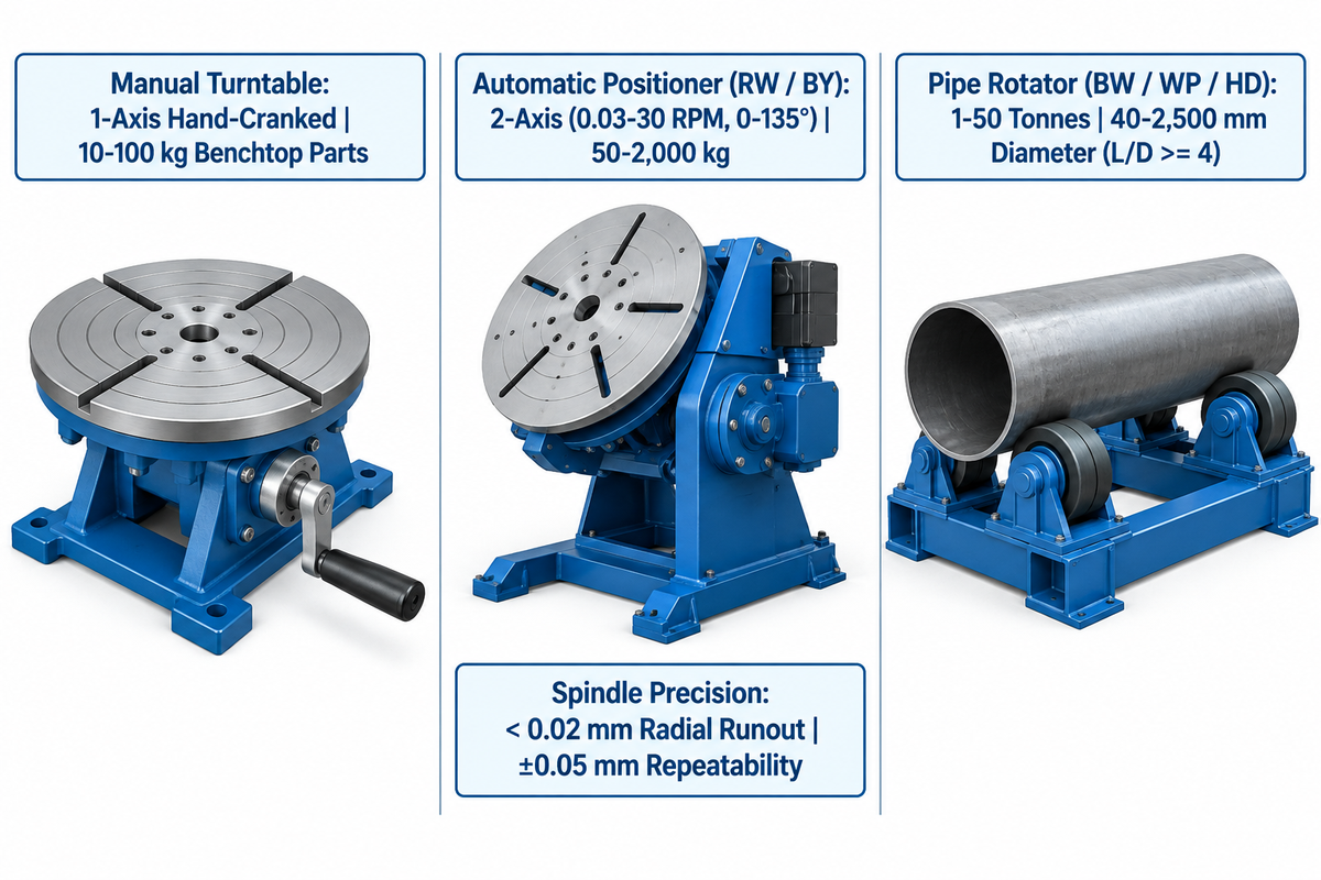
An automatic welding positioner is a motorized workholding machine that clamps a weldment via a T-slot faceplate or 3-jaw chuck. Unlike hand turntables or friction pipe rollers, it controls exact surface velocity and angle.
50 kg–50 tAubrik full positioner ladder
0.03–30 RPMstepless RW-Series rotation speed
< 0.02 mmBY-Series faceplate radial runout
In metal fabrication, the core benefits of using welding positioners come from replacing vertical-up passes with flat deposition. This shift helps shops improve weld quality and consistency while raising deposition rates. According to AWS fabrication research, automated positioning reduces operator fatigue from repetitive welding jobs. Instead, the machine uses its rotation and tilting capabilities to reposition the joint in seconds.
Many welding shops confuse manual turntables, automatic tilt-rotate positioners, and pipe turning rolls. A manual rotating table has hand indexing and is the source of speed fluctuation and cold lap defects. A motorized rotary welding positioner, however, has a variable frequency drive or servo motor that helps maintain the desired arc length. This type of rotary drive acts as a precision rotary table to rotate the workpiece along a programmed path. Every rotary welding pass stays locked at a constant arc length to produce high-quality welds.
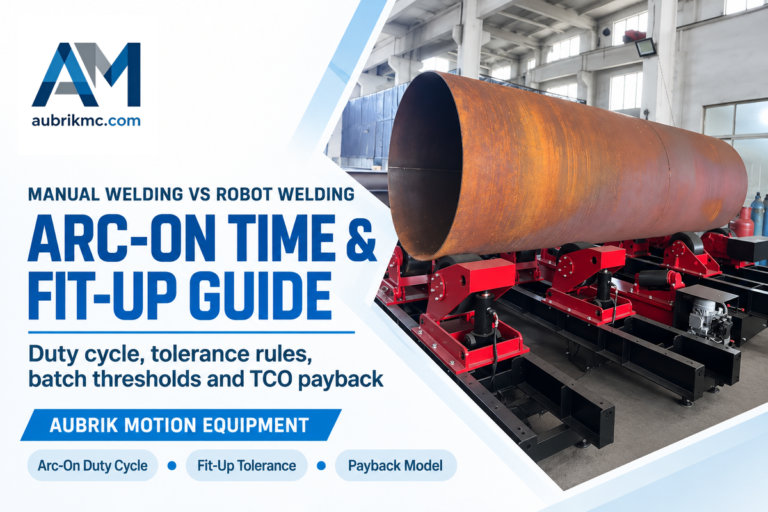
Pipe welding rotators (turning rolls) solve a different geometry challenge. Turning rolls use polyurethane or steel rollers to cradle cylindrical shells from 40 to 2,500 mm in diameter. They support vessel masses from 1 to 50 tonnes without tilting the tank. When the length to diameter ratio of a vessel is 4 or higher, weight is distributed over a greater surface area, and a roller support is more appropriate than a faceplate. Fabricators comparing these two classes of welding equipment can use Aubrik’s interactive Rotator vs. Positioner Selector Tool to match their part geometry.
When an automatic welding system operates inside a mechanized cell, it must meet AWS D16.1M/D16.1:2018 robotic arc welding safety requirements. It covers perimeter safeguarding, emergency stop controls and hazard assessment for powered workpiece rotation.
| Parameter | Manual Welding Turntable | Automatic Tilt-Rotate Positioner (Aubrik RW / BY) | Pipe Welding Rotator (Aubrik BW / WP / HD) |
|---|---|---|---|
| Motion Axes & Drive | 1-axis hand-cranked or basic foot switch | 2-axis motorized rotation (0.03–30 RPM) and tilt (0–135°) | 1-axis VFD stepless friction roller rotation |
| Rated Load Range | 10–100 kg light benchtop parts | 50–2,000 kg standard (custom up to 50 tonnes) | 1–50 tonnes (pipe diameter 40–2,500 mm) |
| Spindle Runout / Repeatability | Uncontrolled manual indexing | < 0.02 mm radial runout; ±0.05 mm repeatability (RW-Series) | Not applicable (cradle roller friction drive) |
| Primary Workpiece Geometry | Small flat flanges and tack-welded fittings | Eccentric elbows, valve bodies, spools, and structural frames | Long cylindrical shells and tanks with L/D ratio of 4 or higher |
How Do Center-of-Gravity Overhang, Eccentricity, and Torque Equations Govern Positioner Sizing?
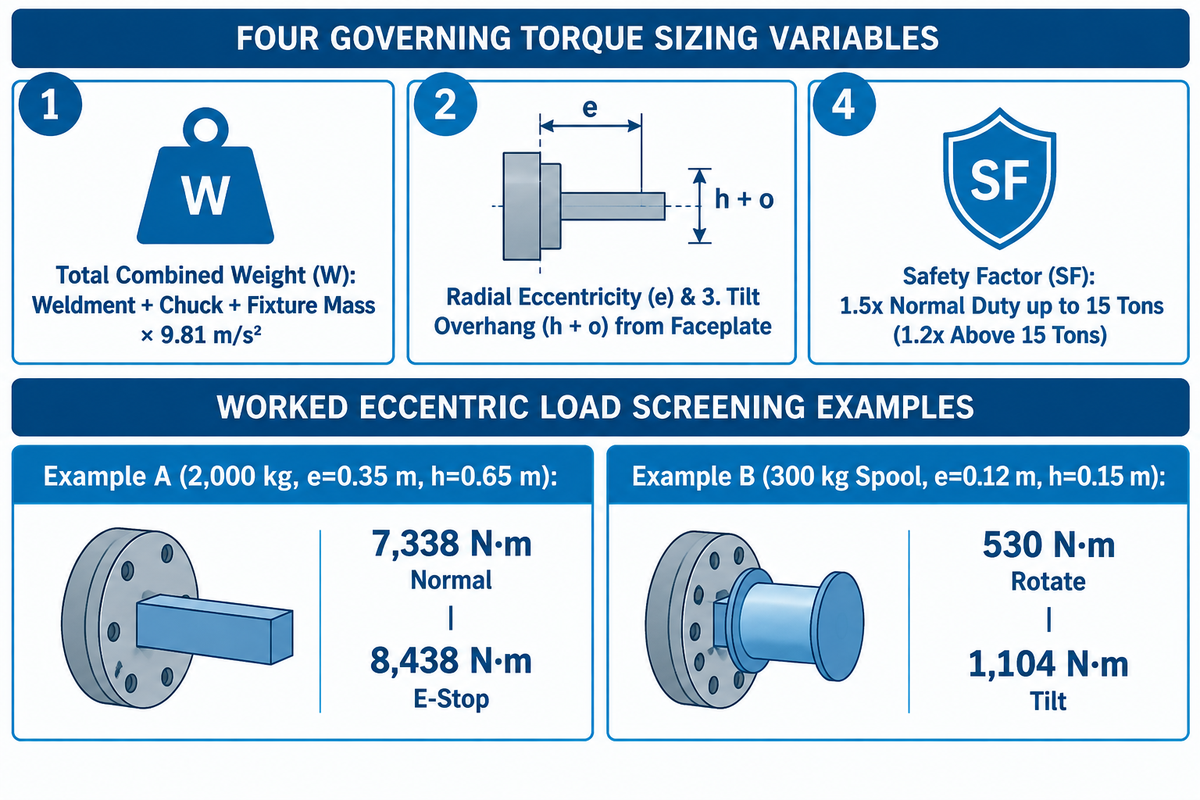
The required torque for the welding positioner is determined by eccentricity and overhang or center of gravity beyond the face of the tool. It’s expressed as rotational and tilt torque equations. For higher capacities, Cyclotron Positioners specifies a 1.5x safety factor for torque up to 15 tons and 1.2x for capacities above 15 tons.
Nameplate payload ratings apply only at zero-degree horizontal table tilt with a centered load, so eccentric fixtures and 90-degree tilting require derating via rotational and overhang torque equations. As described in The Fabricator’s engineering review of welding positioner selection, the required rotational and tilt torque can be evaluated by determining the maximum overhang and the center of gravity distance from the faceplate of the welding positioner.
Ignoring fixture weight is a frequent sizing error in welding and assembly. Cyclotron Positioners notes a clear example for a 4,000 kg fabrication. Selecting a nominal 4-tonne unit ignores 600 kg of fixture weight and pushes actual load to 4,600 kg.
4-Variable Positioner Torque & CoG Derating Calculator
The 4-Variable Positioner Torque & CoG Derating Calculator calculates required drive torque using total mass, radial eccentricity, faceplate overhang, and a safety factor.
To avoid gearbox stripping when tilting into the vertical position, engineers consider the following 4 variables:
- The total combined weight (W) is equal to the weldment mass plus the chuck and fixture masses, all multiplied by the acceleration due to gravity (9.81 m/s²).
- The radial eccentricity (e) is the radial distance from the spindle rotation axis to the combined center of gravity.
- The total tilt overhang (h + o) is the combined center of gravity overhang (h) plus the machine’s internal pivot to faceplate offset (o).
- Safety factor (SF) is 1.5x for normal duty up to 15 tons (1.2x above 15 tons) per Cyclotron Positioners, or 1.5x, 2.0x on Aubrik load charts.
Assumed inputs and screening results for Worked Example A (RV Reducer 2,000 kg L-Type System): In RV Reducer’s published L-type screening model, workpiece mass is 1,500 kg and fixture mass is 500 kg. That gives a combined mass of 2,000 kg (weight W = 19,620 N at g = 9.81 m/s²). Rotary-axis overhang is h = 0.65 m, radial eccentricity is e = 0.35 m, rotary inertia J is 450 kg·m², speed is 5 RPM, normal acceleration is 0.5 s, and emergency stop deceleration is 0.15 s. On these RV Reducer inputs, horizontal overturning moment is 19,620 N times 0.35 m (6,867 N·m) and vertical faceplate overturning moment is 19,620 N times 0.65 m (12,753 N·m). Adding 471 N·m normal acceleration torque (or 1,571 N·m emergency-stop torque) to the 6,867 N·m gravity torque yields 7,338 N·m normal torque and 8,438 N·m emergency-stop torque.
Assumed inputs and screening results for Worked Example B (300 kg Pipe Spool on Cantilevered Faceplate): A 260 kg eccentric pipe spool sits in a 40 kg 3-jaw chuck for a 300 kg total mass (2,943 N). Radial eccentricity is e = 0.12 m, faceplate overhang is h = 0.15 m, and internal pivot offset is o = 0.10 m at 90° tilt. Baseline rotational torque is 2,943 N times 0.12 m, or 353 N·m (530 N·m at a 1.5x safety factor). Baseline tilting torque is 2,943 N times 0.25 m, or 736 N·m (1,104 N·m at a 1.5x safety factor). Because 150 mm overhang exceeds a 300 kg benchtop rating at 90° tilt, the buyer steps up to an Aubrik BY-500 or BY-1000 positioner table.
Next engineers compare rotation speed to the desired welding travel speed. In The Fabricator’s tube and pipe positioner guide, operators multiply pipe diameter by 3.14 to find circumference. To find the RPM, the linear arc speed needs to be divided by the circumference. Aubrik recommends a surface speed of 150-400 mm/minute for hand MIG or TIG welding and a surface speed of up to 1,500 mm/minute for submerged arc welding (SAW). Automated cells also set speed limits under AWS D16.1M/D16.1:2018.
When Should You Choose a 2-Axis Tilt-Rotate Positioner vs. a Headstock-Tailstock or 3-Axis Elevating System?
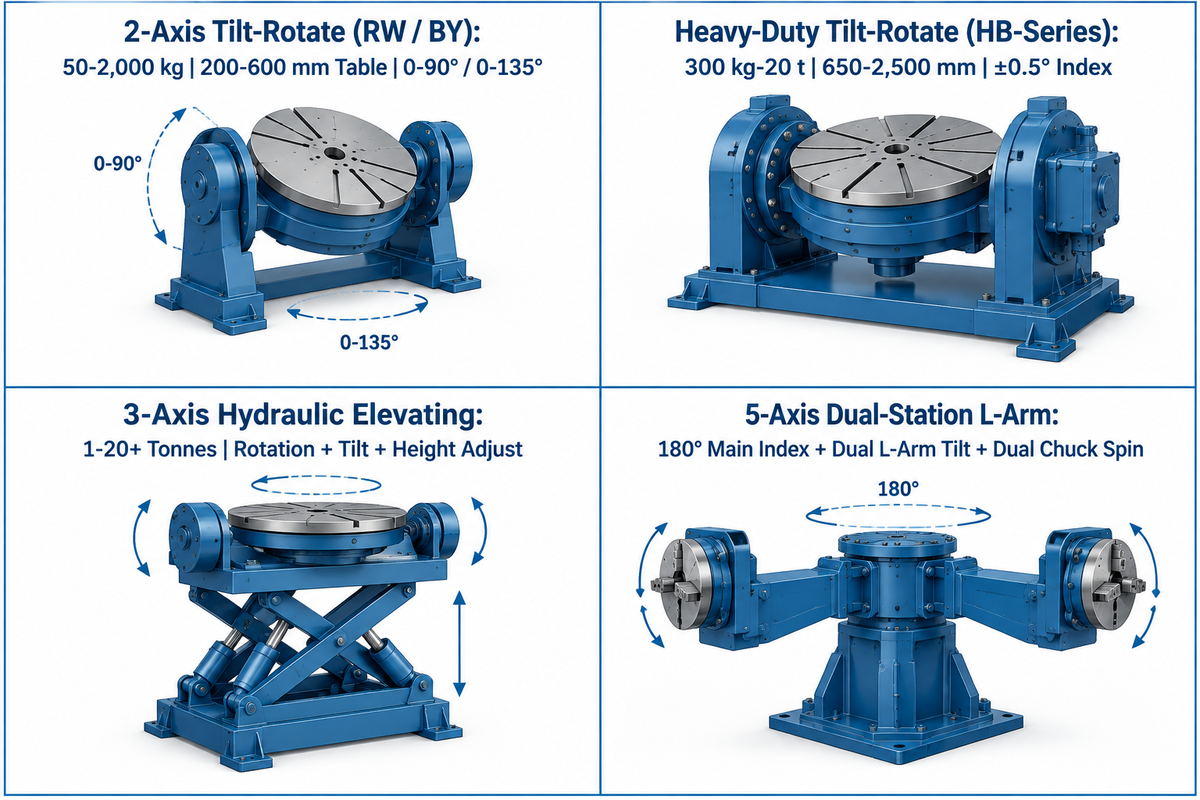
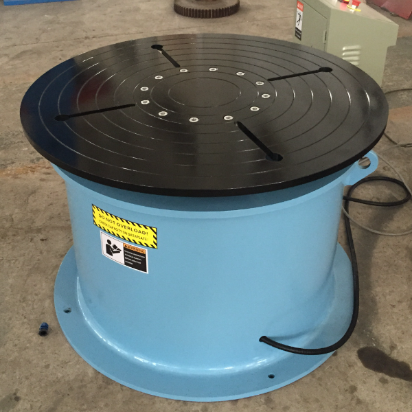
Select a 2-axis tilt-rotate table positioner when cantilevered weldments have a center-of-gravity overhang under 300 mm. Switch to a dual-column headstock-tailstock system when part span exceeds 1.8 m, or specify a 3-axis elevating unit with height adjustment when large swing radii need floor clearance.
Industrial weld positioners fit in specific welding envelopes using various sizes and configurations. Matching frame geometry to your part prevents torch collisions and saves floor space. Understanding the different types of welding positioners helps engineers provide a stable platform for a wide variety of welding tasks.
In a 2-axis tilt-rotate system, compact valves, flanges, and manifolds use the smallest footprint. Long truck frames and crane booms cause excessive cantilever bending on a single faceplate. A headstock-tailstock system supports weldments between two synchronized columns along the horizontal axis. Engineers handling oversize assemblies can read our guide on sizing a large welding positioner for oversize structural weldments for foundation rules.
In high-volume robotic welding applications, dual-station designs eliminate loading wait time and increase productivity. One example of this type of design is utility model patent CN121339620A (Xuzhou Huaheng Robot System Co. Ltd.), which contains a five-axis hollow positioner design. It combines a main rotary box, two L-shaped arms, two turnover boxes, and two rotary tables. Once one side of the turnover box completes welding, the main slewing drive of the positioner rotates 180 degrees and changes stations to repeat the process continuously.
| Positioner Architecture | Axes & Motion | Load & Table Envelope | Best Workpiece Fit |
|---|---|---|---|
| 2-Axis Tilt-Rotate (Aubrik RW / BY) | 360° continuous rotation + 0–90° or 0–135° tilt | 50–2,000 kg; table 200–600 mm | Cantilevered pipe spools, manifolds, and valve bodies |
| Heavy-Duty Tilt-Rotate (Aubrik HB-Series) | 0.05–2 RPM rotation + 0–90° / 0–120° tilt; ±0.5° index | 300 kg–20 t standard (50 t custom); table 650–2,500 mm | Large and heavy gear housings, turbine rings, and Q355B frames |
| 3-Axis Hydraulic Elevating | Rotation + tilt + vertical table height adjustment | 1–20+ tonnes with variable floor clearance | Deep-profile weldments requiring ergonomic table height |
| 5-Axis Dual-Station L-Arm (CN121339620A) | 180° main station index + dual L-arm tilt + dual chuck spin | Dual-station robotic cell payload | High-volume automotive and complex welding sub-assemblies |
How Do Payload Tiers Scale from 50 kg Benchtop Units to 2,000 kg Heavy-Duty Tilt-Rotate Positioners?
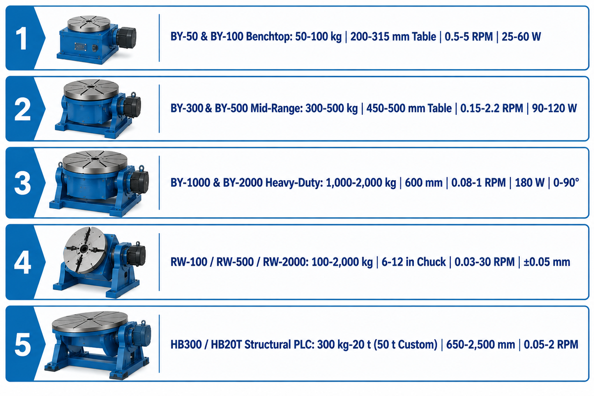
Automatic welding positioners scale across three payload tiers: 50–100 kg benchtop turntables (25–60 W motors, 0.5–5 RPM) and 300–500 kg mid-range units (90–120 W, 0.15–2.2 RPM) for pipe spools. Heavy structural assemblies use 1,000–2,000 kg floor units (180 W, 0.08–1 RPM) with 0–90° motorized tilt.
As The Fabricator notes, benchtop units typically handle payloads from 50 to 250 lb (23 to 113 kg) for small pipe welding and tube assemblies. Above that tier, floor-anchored frames and motorized tilt trunnions take over. Fortune Business Insights reports that the global robotic welding market stood at USD 8.10 billion in 2025. It is projected to grow from USD 9.00 billion in 2026 to USD 27.90 billion by 2034 at a 15.20% CAGR. This expansion drives demand for 300–2,000 kg robotic welding positioners built to ANSI/A3 R15.06-2025 safety standards.
The specification table for the Aubrik BY Series reflects the factory-direct catalog parameters of Aubrik (50 kg to 2,000 kg). Other OEMs configure motor wattage and table diameters differently across similar tonnage classes. Buyers reviewing frame drawings can inspect industrial automatic welding positioners in the 50 kg to 2,000 kg BY Series on Aubrik’s website.
| Model | Payload Tier & Class | Rated Load Capacity | Table Diameter | Rotation Speed Range | Motor & Tilt Specification |
|---|---|---|---|---|---|
| BY-50 | Light Benchtop Turntable Tier | 50 kg | 200 mm | 0.5–5 RPM | 25 W drive; manual tilt; runout < 0.02 mm |
| BY-100 | Benchtop Turntable Tier | 100 kg | 315 mm | 0.5–5 RPM | 60 W drive; worm tilt; runout < 0.02 mm |
| BY-300 | Mid-Range Spool Positioner Tier | 300 kg | 450 mm | 0.15–2.2 RPM | 90 W drive; floor tilt; runout < 0.02 mm |
| BY-500 | Mid-Range Floor Positioner Tier | 500 kg | 500 mm | 0.15–2.2 RPM | 120 W drive; floor tilt; runout < 0.02 mm |
| BY-1000 | Heavy-Duty Motorized Tilt Tier | 1,000 kg | 600 mm | 0.08–1 RPM | 180 W drive; 0–90° motorized tilt; runout < 0.02 mm |
| BY-2000 | Heavy-Duty Motorized Tilt Tier | 2,000 kg | 600 mm | 0.08–1 RPM | 180 W drive; 0–90° motorized tilt; runout < 0.02 mm |
| RW-100 | Precision Rotary Chuck Tier | 100 kg | 6–12 in chuck | 0.03–30 RPM | 0–135° tilt; ±0.05 mm repeatability |
| RW-500 | Precision Rotary Chuck Tier | 500 kg | 6–12 in chuck | 0.03–30 RPM | 0–135° tilt; ±0.05 mm repeatability |
| RW-2000 | Heavy Precision Rotary Tier | 2,000 kg | 6–12 in chuck | 0.03–30 RPM | 0–135° tilt; ±0.05 mm repeatability |
| HB300 / HB20T | Industrial Structural PLC Tier | 300 kg–20 t (50 t custom) | 650–2,500 mm | 0.05–2 RPM | 0–90° / 0–120° tilt; ±0.5° index; Q355B frame |
DC Servo, Stepper, or VFD Worm-Gear Drive: Which Motor and Reducer Architecture Fits Your Weld Tolerance?
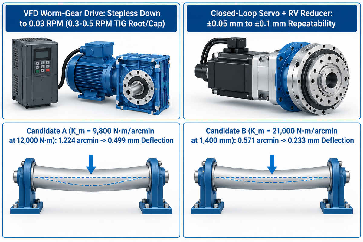
An AC motor with a worm-gear reducer and a self-locking clutch achieves continuous circumferential welds using MIG or SAW. Servo drives with RV cycloidal reducers (repeatability of ±0.05 mm to ±0.1 mm) are used for multi-pass TIG and welding using robots where low backlash and high torsional stiffness is required.
Open-loop VFD worm-gear positioners provide continuous rotational speed control, whereas synchronized multi-axis robotic path interpolation requires closed-loop servo drives and zero-backlash RV or planetary reducers. For circumferential pipe work, low-speed smoothness directly impacts weld quality. Aubrik rotary positioners run a stepless VFD drive down to 0.03 RPM. That sits well below the 0.3–0.5 RPM needed for root and cap TIG passes on large pipes. Many budget turntables bottom out near 2 RPM and ruin precise welding control.
In automated welding cells, the drive train must stand eccentric bending loads, and the speed and safety monitoring circuits must comply with AWS D16.1M/D16.1:2018.
Assumed inputs and screening results for Worked Example C (Reducer Tilting Stiffness & Seam Deflection): Reducer tilting stiffness controls seam tracking accuracy during the welding process. In RV Reducer’s published stiffness model under an assumed 12,000 N·m overturning moment at a 1,400 mm radial weld distance, Candidate A (tilting stiffness K_m = 9,800 N·m/arcmin) deflects 1.224 arcmin and causes 0.499 mm of seam displacement. Under that same assumed load, Candidate B (tilting stiffness K_m = 21,000 N·m/arcmin) cuts tilt deflection to 0.571 arcmin and reduces seam displacement to 0.233 mm.
Where ultra-precise rotary indexing is required, roller-gear cam indexers such as Sankyo Automation’s RW-320 achieve ±5 arc-seconds repeatability. They also hold ±15 arc-seconds indexing accuracy at 500 N·m output torque. By contrast, unshielded stepper motors often stall or lose steps during high-frequency arc welding starts.
What Spindle Bore, Self-Centering Chuck, and HF Grounding Protections Are Required for Pipe and TIG Welding?
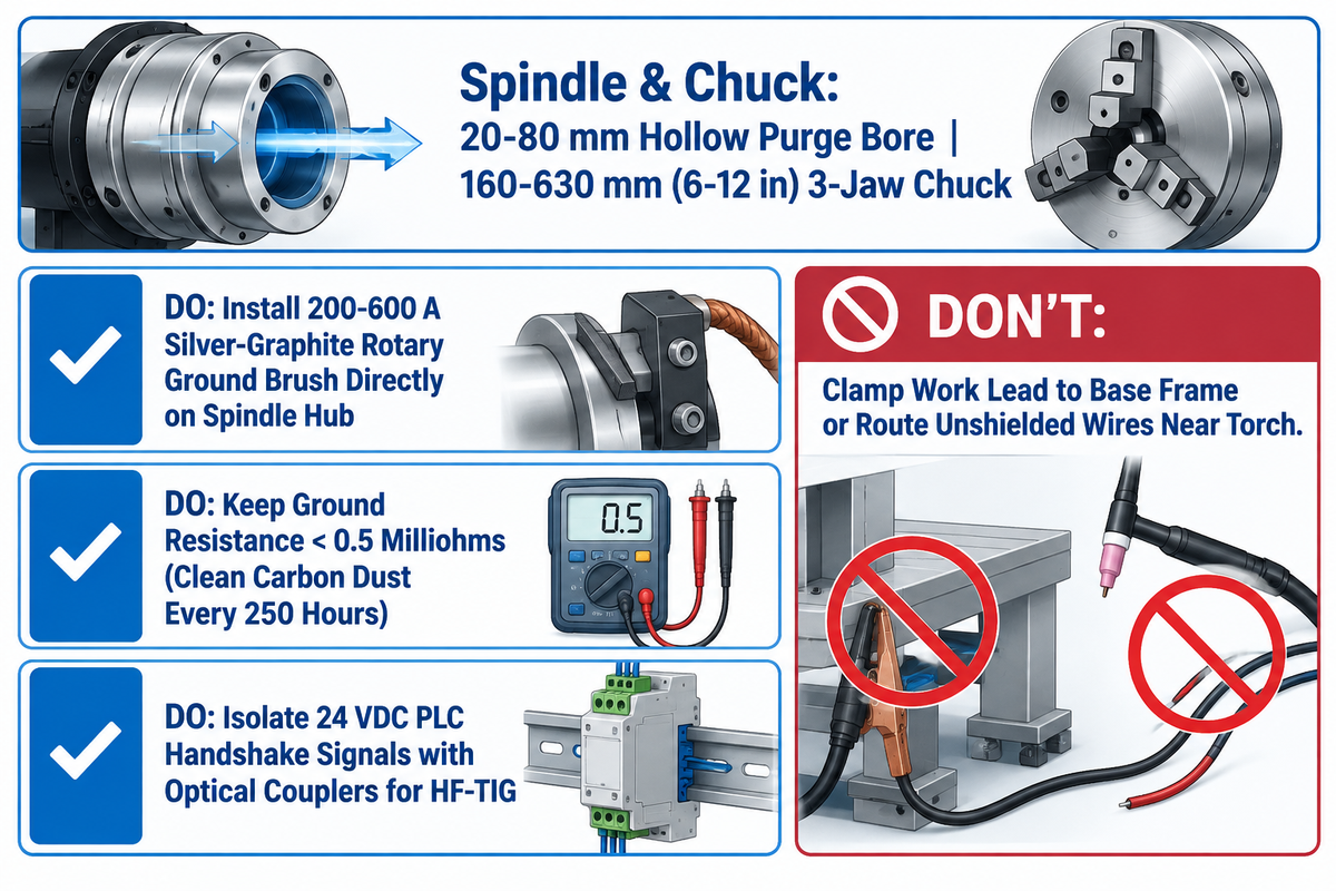
Automated pipe and TIG welding require three mechanical protections: a 20–80 mm hollow spindle through-bore for argon back-purging and a 160–630 mm 3-jaw self-centering welding chuck. Every spindle also needs a dedicated 200–600 A silver-graphite rotary ground brush that bypasses spindle bearings and prevents electrical pitting.
When welding stainless steel or titanium tubing, the oxygen in the bore oxidizes the root pass. For this reason, a 20-80 mm hollow bore in a spindle enables operators to pass an argon line through the turntable center. This allows for unrestricted 360-degree movement of the purge hose during turntable. A 3-jaw self-centering chuck (6-12 inch on RW models or 160-630 mm on all models) holds the stock concentrically. Advanced chucks, like the model in patent CN121339620A, incorporate a gear-driven mechanism to support rapid clamping with a copper alloy clamping pad.
Electrical return currents to the power supply through the spindle bearings must be avoided for high-quality automated welding. In The Fabricator’s benchtop positioner guidelines, a 200-amp rotary ground is the minimum rule of thumb for small units. Industrial positioners scale to 300–600 A silver-graphite shoes. Pitting of the races and seizing of the gearbox is caused by electrical arcing across the roller bearings. Read our precision TIG turntable RPM-to-torque sizing and HF grounding guide for EMI isolation wiring details.
Do
- Install a dedicated 200–600 A silver-graphite rotary ground brush directly against the spindle hub.
- Keep rotary ground resistance below 0.5 milliohms by cleaning carbon dust every 250 arc-on hours.
- Isolate all 24 VDC PLC handshake signals with optical couplers during high-frequency TIG starts.
Don’t
- Clamp the welder work lead to the stationary base frame, which forces current through bearings.
- Route unshielded stepper or sensor wires parallel to high-frequency TIG torch cables.
- Exceed tilted center-of-gravity torque ratings when mounting heavy chucks on benchtop turntables.
How Do You Integrate an Automatic Welding Positioner with Cobots, 6-Axis Robots, and PLC Fieldbus Networks?
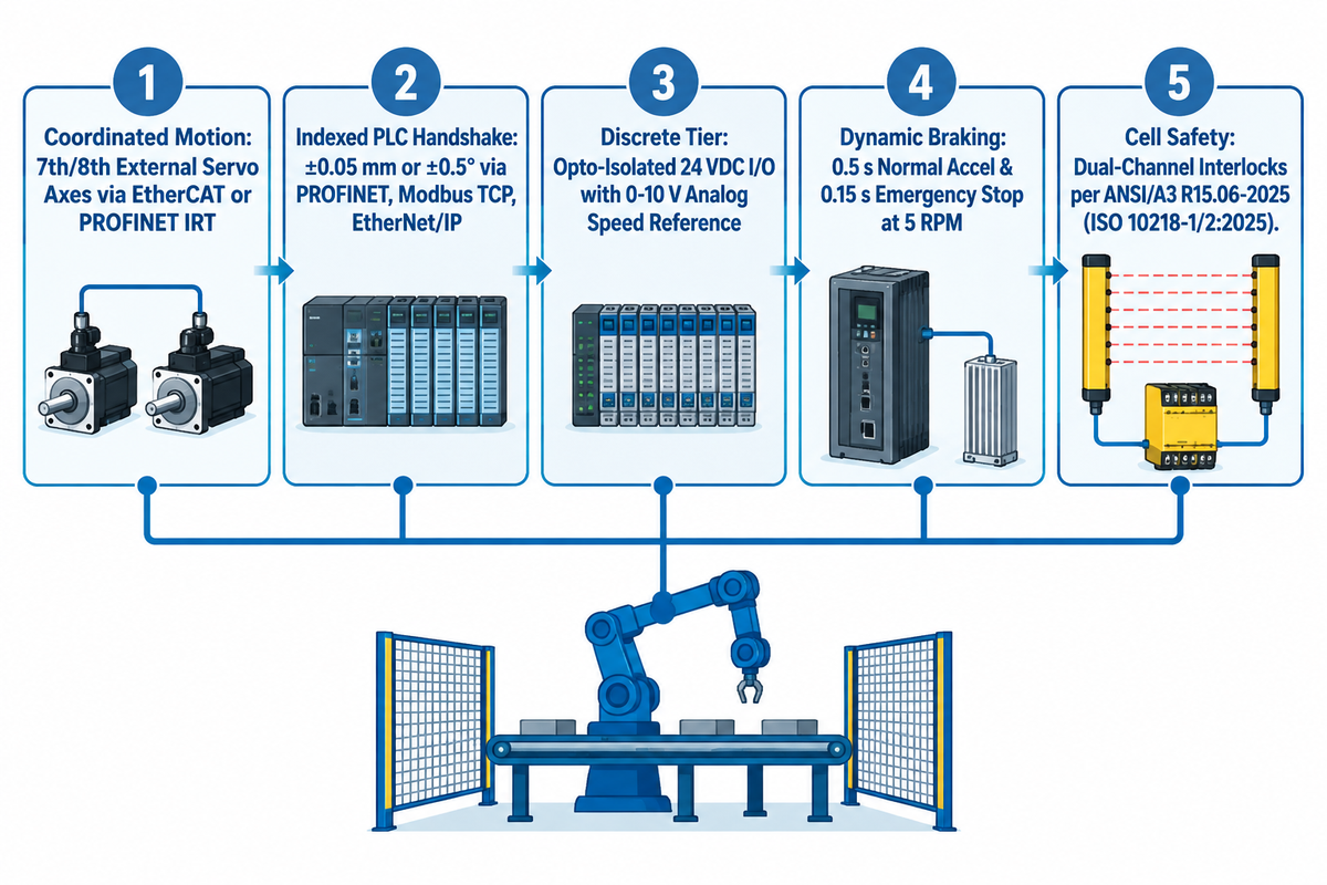
Integration of a automatic welding positioner into a robotic welding cell follows three control tiers. Cells use synchronized 7th/8th external servo axes over EtherCAT or PROFINET IRT, indexed PLC handshaking over PROFINET or Modbus TCP, or opto-isolated 24 VDC discrete I/O with a 0-10 V speed reference.
When upgrading from a manual setup to welding automation, the link between the gas shielded welding machine, robot controller, and positioner governs productivity. This integration allows the torch to complete complex welding paths in one clamping cycle and improve weld quality. Our automated and robotic welding cell architecture guide offers design patterns for safety fencing and positioner envelopes for cell designers.
5-Point Cobot & TIG Positioner Integration Matrix
The 5-Point Cobot & TIG Positioner Integration Matrix is a guide for weld joint geometries and servo axis coordination, fieldbus and safety interlocks.
- Torch motion and rotation interpolate together on saddle welds controlled by 7th or 8th external servo axes that originate from the robot amplifier via EtherCAT or PROFINET IRT.
- Handshaking over a fieldbus indexes the position of parts to within ±0.05 mm or ±0.5° using a Siemens PLC and HMI over PROFINET, Modbus TCP, or EtherNet/IP.
- Cells use synchronized 7th/8th external servo axes over EtherCAT or PROFINET IRT, indexed PLC handshaking over PROFINET or Modbus TCP, or opto-isolated 24 VDC discrete I/O with a 0–10 V speed reference.
- Dynamic stop and inertia checks ensure ratings of the brakes can withstand 0.5 s normal acceleration and 0.15 s emergency stops at 5 RPM under tilted gravity torque.
- Dual-channel safety interlocks wire emergency stops and light curtains per ANSI/A3 R15.06-2025 (Parts 1, 2, and 3). That 403-page standard was published October 29, 2025 and adopts ISO 10218-1/2:2025.
How Should Buyers Evaluate Manufacturers, Lead Times, and Factory Acceptance Testing (FAT) Across 50–2,000 kg Systems?
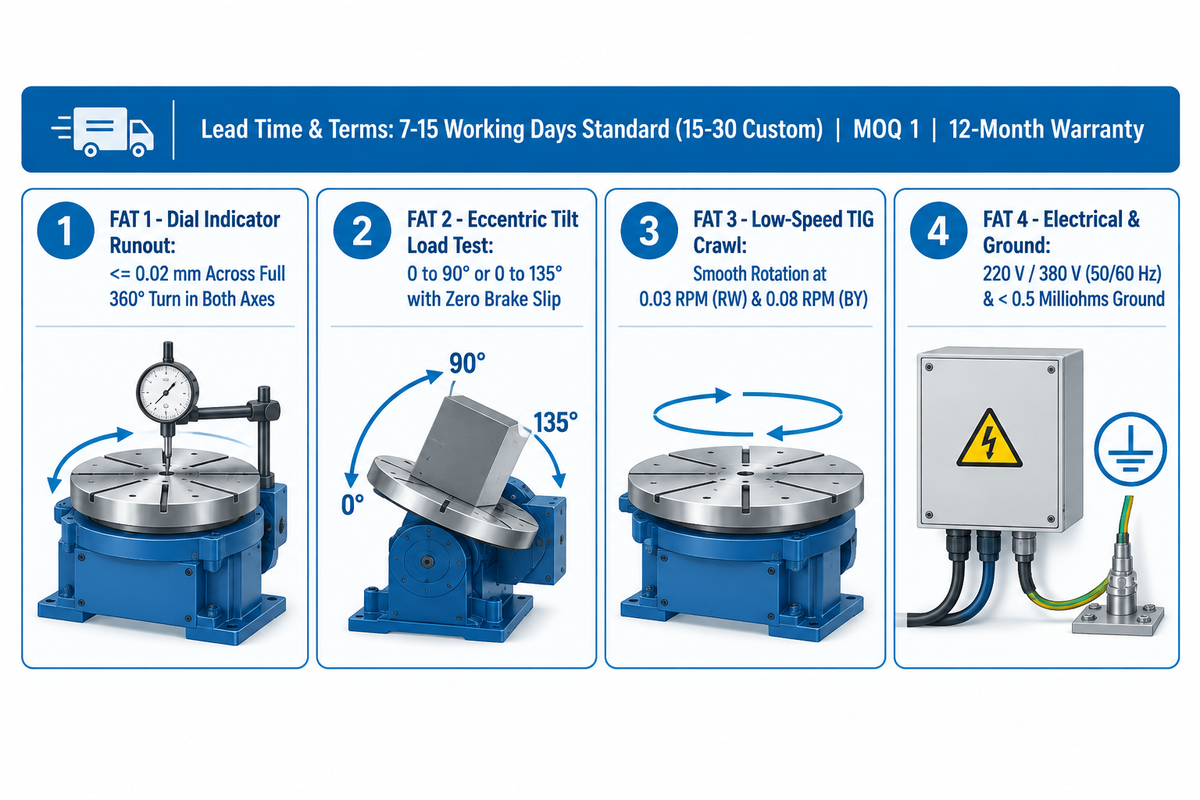
Evaluate automatic welding positioner manufacturers by verifying ex-works build times (7–15 working days for standard Aubrik units, 15–30 working days for custom builds). Buyers should also confirm grid voltage support (220 V or 380 V, 50/60 Hz), MOQ of 1 unit, and a 4-point Factory Acceptance Test confirming sub-0.02 mm runout.
Procurement teams comparing global brands (Koike Aronson, Pemamek, Bode, or Cyclotron) against factory-direct builders like Aubrik (Wuxi ABK Machinery Group) should audit lead times and customization. According to Aubrik’s published welding positioner specifications, standard units ship in 7–15 working days (15–30 working days custom) with a 1-year (12-month) warranty and MOQ 1.
Quoted transit windows (7–10 days by air freight and 14–21 days by sea freight) cover standard catalog positioners after ex-works completion and exclude destination customs clearance or bespoke multi-axis engineering cycles. Before shipment, buyers should require a Factory Acceptance Test (FAT) aligned with AWS D16.1M/D16.1:2018 and ISO 9001 quality procedures:
- Dial indicator runout inspection determines if faceplate runout and runout in both axes are less than or equal to 0.02 mm for a full 360° turn.
- 0 to 90° or 0 to 135° load testing is performed for tilting under eccentric torque to confirm no brake slip.
- Low-speed TIG crawl testing is performed to check if rotation is smooth at a minimum speed of 0.03 RPM for RW-Series, and 0.08 RPM for BY-1000/BY-2000.
- Grid and rotary ground verification confirms 220 V or 380 V (50/60 Hz) wiring and checks that rotary ground resistance stays below 0.5 milliohms.
Key takeaway
Size every automatic welding positioner with a 1.5x safety factor on 90-degree tilted center-of-gravity torque (part plus chuck mass), and verify sub-0.02 mm runout before shipment.
Need an Eccentric Load & Torque Sizing Check for Your Weldments?
You can share your part drawing, workpiece mass, and chuck envelope with our mechanical engineers. A custom CoG torque calculation and factory quote from Aubrik Engineering (MOQ 1 unit; 7 to 15 working days for delivery) can be arranged.
Frequently Asked Questions About Automatic Welding Positioners
Can an automatic welding positioner rotate continuously while a cobot or MIG torch welds?
Yes, continuous rotation is standard for circumferential pipe and flange seams.
On circular joints, the positioner spins at a programmed surface speed while the cobot or fixed torch stays in the 1G flat position. For contoured saddle welds, elliptical nozzles, or off-center elbows, the positioner operates as a synchronized seventh or eighth servo axis over EtherCAT or PROFINET IRT. That servo link allows torch motion and the table rotation to interpolate together without path lag.
How do you prevent high-frequency TIG arc starts from resetting a programmable welding positioner controller?
Install a 200 to 600 ampere silver-graphite rotary ground brush below the faceplate, and drive an independent copper ground rod to the control cabinet.
Route all VFD or servo motor leads inside grounded metal conduit away from the TIG torch cable. Optically isolate the 24 VDC PLC start/stop handshake signals and fit EMI line filters on the cabinet power input.
What is the difference between rated horizontal load capacity and 90-degree tilted load capacity on a rotary positioner?
The rated horizontal capacity assumes a flat table at zero degrees with a centered load over the main thrust bearing.
When a table is tilted to 90 degrees, the vertical weight becomes a cantilevered bending and overturning moment on the spindle and tilt gears. Even a 5,000 lb rated unit drops to roughly half capacity on its side and derates further as center-of-gravity overhang increases. This derating is why a 1.5x safety factor is applied to eccentric load charts.
When do you need a hollow spindle through-bore on an automatic welding positioner?
It’s preferred to specify a 20 to 80 millimeter hollow spindle on the through-bore of the turntable. It also protects internal argon back-purging hoses during 360-degree rotation on stainless steel and titanium pipes.
How often should the rotary ground carbon brush and worm-gear reducer be serviced in automated welding cells?
Inspect the rotary ground carbon brush and spring tension every 250 arc-on hours to keep contact resistance below 0.5 milliohms.
In two-shift production, check worm-gear or RV reducer backlash and synthetic gear oil levels every 1,000 operating hours. Measure faceplate radial runout with a dial indicator annually to maintain sub-0.02-millimeter seam tracking accuracy.
About This Engineering Guide: Compiled by CYH, the Aubrik Mechanical Engineering Team, and dynamometer logs from BY- and RW-Series models, coupled with the ANSI/AWS robotic safety standards, and RV reducer stiffness models.
References & Sources
- The Future of Fabrication: Collaborative Robots and Automated Positioning American Welding Society (AWS)
- AWS D16.1M/D16.1:2018 Specification for Robotic Arc Welding Safety American National Standards Institute (ANSI) / American Welding Society
- Tons of Reasons for a New Welding Positioner: Center of Gravity and Overhang Sizing The Fabricator (Fabricators & Manufacturers Association)
- Putting the Spin on Benchtop Positioners for Tube and Pipe Welding The Fabricator (Fabricators & Manufacturers Association)
- CN121339620A: Five-Axis Hollow Welding Positioner Device Google Patents / China National Intellectual Property Administration
- ANSI/A3 R15.06-2025 American National Standard for Industrial Robots and Robot Systems Safety Requirements American National Standards Institute (ANSI) / Association for Advancing Automation (A3)