Get in Touch with Aubrik Company

(Last updated November 2026 · Reviewed by Aubrik Company technical team)
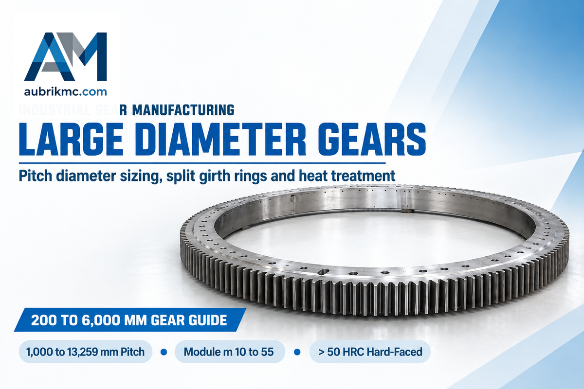
Quick Engineering Specifications: Large Diameter Gears
- Industrial pitch diameter envelope spans 1,000 mm to 13,259 mm across normal modules m = 10 to m = 55.
- Segmented bolted girth gears provide an alternative to one-piece rolled forged rings above 4,000 mm outside diameter (OD).
- Hard-faced gear drives require surface hardness above 50 HRC (50–56 HRC induction hardened or 58–62 HRC carburized).
- Flank accuracy grades follow ISO 1328-1:2013 and DIN 3962 / AGMA 2000 with ASTM A388 ultrasonic forging inspection.
- Aubrik rotary drives hold ≤0.02 mm radial runout across 50-2,000 kg positioners and 1-1,000 T turning rolls.
Giant gears transmit heavy rotational forces found in large equipment such as ball mills, rotary kilns, wind yaw drives, and automated welding positioners. Engineers specifying a gear system over 1,000 mm (pitch diameter) face constraints that don’t exist in smaller catalog drives. Forgings ring capacity, over-dimensional shipment widths, heat treatment distortion, and many other constraints control every step in the gear design process.
When two gears mesh under multi-megawatt loads, minor pitch errors or shaft deflections rapidly cause tooth root failure. Achieving proper gear selection is a result of balancing module math, split ring joint preloads and ultrasonic forging inspection. Those looking for custom rings and rotary drives, can contact Aubrik for custom industrial gear and ring gear manufacturing. Aubrik engineers can provide the necessary engineering support for an application.
Direct Engineering Answer: Large diameter gears are heavy-duty cylindrical or bevel power transmission rings exceeding 1,000 mm in pitch diameter with modules from m = 10 to m = 55. They use forged 42CrMo or 20CrMnTi alloy steel, split-flange bolting above 4,000 mm, and ISO 1328-1 flank tolerances.
Key Engineering Takeaways (TL;DR)
- Separate three architectures early: shaft-mounted enclosed bull gears (1,000–5,000 mm), shell-mounted open girth gears (3,000–13,259 mm), and bearing-integrated slewing ring gears (400–6,000 mm).
- Size pitch diameter via d = m × z and apply a 1.5x to 2.5x safety factor. On a 3,200 mm girth gear (m = 20, z = 160), a 450 kN·m load imposes 281.25 kN of tangential tooth force.
- Above 2,000 mm pitch diameter, full-furnace carburizing quench distortion often outweighs the benefits of higher HRC hardness unless post-quench CNC form grinding is included in the budget.
- Verify every forged gear blank with volumetric pulse-echo ultrasonic testing according to ASTM A388/A388M before teeth are cut.
What Defines Large Diameter Gears? Bull Gear, Girth Gear, and Ring Gear Architecture
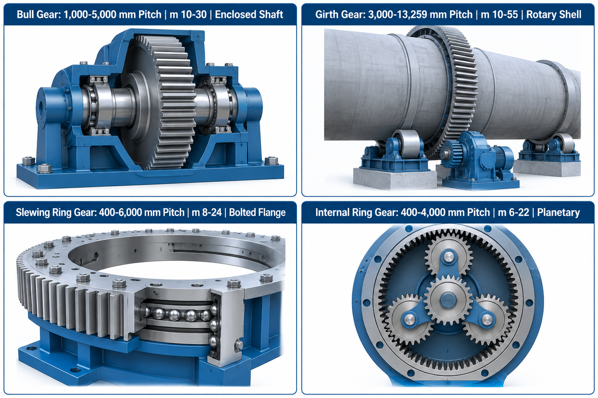
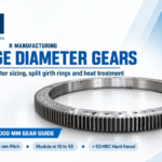
Large diameter gears are industrial power transmission gears with pitch diameters from 1,000 mm to 13,259 mm and normal modules between 10 and 55. The classification of these gears depends on the load path and mounting geometry and includes shaft mounted bull gears, shell mounted girth gears and bearing integrated slewing ring gears.
200–6,000 mmAubrik industrial gear capability
> 50 HRCHard-faced tooth flank threshold
≤0.02 mmAubrik ISO 9283 radial runout
In general machine shops, any gear blank above 500 mm is treated as large. In heavy machinery for mining, cement, wind yaw drives, and automated welding, the threshold starts at 1,000 mm. These gear pairs use hardened steel pinion gears to drive a huge mating wheel at high torque.
Lack of understanding of bull gears, girth gears, and slewing ring gears, during the layout leads to expensive housing and foundation mismatches. Each architecture manages axial, radial and overturning moments differently. Flank geometry and tooth deviation limits across all three classes follow ISO 1328-1:2013 cylindrical gear flank tolerance standards.
A bull gear mounts onto a central forged shaft inside an enclosed, oil-bath gearbox. It typically measures 1,000 mm to 5,000 mm in pitch diameter. One or two pinions mesh with the bull gear to multiply torque in marine reduction drives and stamping presses.
A girth gear is a ring gear affixed to the exterior of a cylinder. For more information, please see Oxmaint’s cement plant girth gear engineering checklist. The girth gear is the largest open gear drive in most plants. For larger diameters, segmented girth gears are required (as per industrial large gear manufacturing benchmarks at 4 meters/4,000 mm). The largest mill ring gear, per Aubrik’s industrial gear engineering data, is run by Falk and measures 13,259 mm outside diameter, across six segments.
A slewing ring gear integrates internal or external gear rings with hardened raceways for ball or cross-roller bearings. Slewing rings that vary in diameter from 400 mm to 6,000 mm support axial loads, radial shear, and tilting moments in one compact unit. Aubrik produces industrial gears up to 6,000 mm in diameter through its custom industrial gear and ring gear manufacturing division. These heavy gears use precision slewing drives across 50–2,000 kg turntables and 1–1,000 T turning rolls.
| Architecture Type | Pitch Diameter Range | Normal Module (m) | Mounting & Enclosure | Primary Industrial Machinery |
|---|---|---|---|---|
| Bull Gear | 1,000–5,000 mm | m 10–30 | Shrink-fitted or keyed to shaft inside enclosed oil gearbox | Marine propulsion, stamping presses, compressor drives |
| Girth Gear | 3,000–13,259 mm | m 10–55 | T-bolt or spring-plate mounted to rotary shell; guard-enclosed | Ball mills, SAG mills, rotary kilns, dryer drums |
| Slewing Ring Gear | 400–6,000 mm | m 8–24 | Bolted flange ring with integrated ball or roller raceways | Welding positioners, crane turrets, 5 MW wind yaw drives |
| Internal Ring Gear | 400–4,000 mm | m 6–22 | Housing-mounted outer ring meshing with planet pinions | Planetary gearboxes, tunnel boring machines, roller presses |
Spur Gear, Helical Gear, Double Helical, and Internal Gear Topologies at Scale
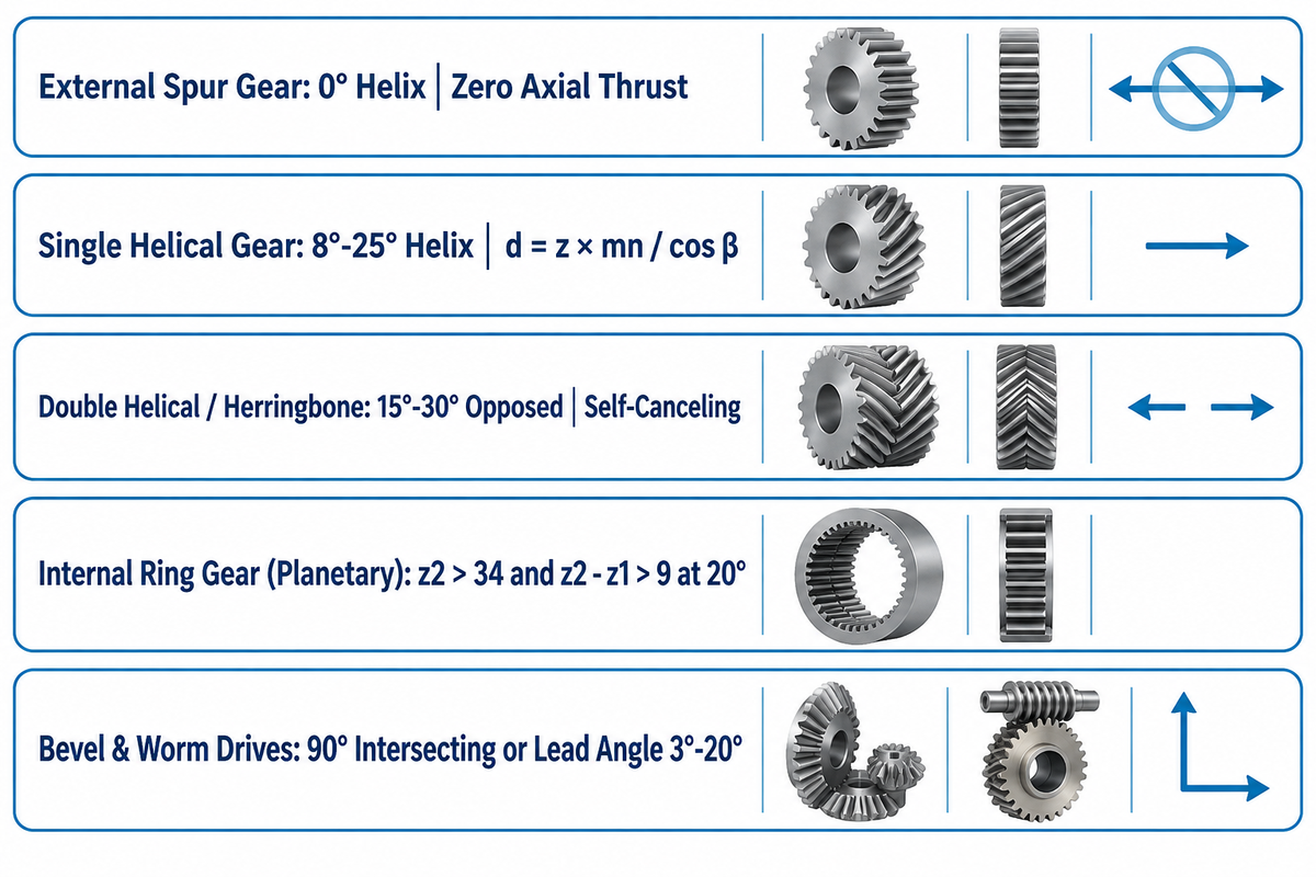
Different topologies for torque platforms are available, including spur gear, helical gear, double helical gear, internal gear, bevel gear and worm gear. The choice depends on limitations of axial thrust, contact ratio and shaft orientation. Spur gears eliminate axial thrust on open shells, and double helical gears maximize torque capacity without overloading thrust bearings.
When evaluating various types of gears for heavy drives, engineers base their decisions primarily on the shaft geometry and bearing layout. Every cylindrical gear transmits motion between parallel shafts. Bevel and worm gearing handle motion for intersecting and skewed axes. Geometric definitions for these gear types follow ISO TC 60 gear standards and KHK’s gear dimension calculation tables.
spur gear features straight spur gear teeth cut parallel to the gear axis. Because the helix angle is zero degrees, a spur gear generates zero axial thrust along the shaft. Therefore, external gears with straight teeth remain the standard choice for rotary kiln girth gears where thermal shell expansion occurs.
A helical gear cuts teeth at a helix angle beta (typically 8° to 25°) relative to the axis. In the normal helical system defined by KHK Table 4.3, pitch diameter equals d = z × mn / cos β. Single helical gears offer higher load ratings than spur gears, but the angled helix creates axial thrust that requires heavy thrust bearings.
A double helical gear (or herringbone gear) places left-hand and right-hand helices side by side on the same ring. The two opposing axial thrust vectors cancel each other out inside the gear blank. Double helical designs deliver smooth operation and high torque density in enclosed mill drives.
An internal gear or machining teeth on the inside diameter of a outer ring gear is often part of a planetary gear process. In this case, multiple planet pinions orbit a central sun gear in the internal fixed ring. As stated by KHK Table 4.9, to avoid involute and trochoid interference at a 20° pressure angle, an internal gear tooth count of above 34 (z2 > 34) and a tooth difference of above 9 (z2 – z1 > 9) is required.
In situations where shafts don’t run parallel, engineers specify specialized non-parallel configurations. A bevel gear or spiral bevel gear is designed to transmit power between intersecting shafts at 90 degrees. A hypoid gear offsets the pinion axis below the ring centerline to increase the pinion diameter. A worm gear provides high reduction and self-locking safety against unwanted tilts, and a rack and pinion uses straight or helical gear racks to convert rotary torque into linear motion.
What Is the Difference Between Helical Gears vs Spur Gears in Heavy Drives?
The core mechanical difference between helical gears and spur gears lies in tooth engagement progression and axial thrust. For a spur gear, the entire face width of each tooth snaps into line contact at once. The sudden impact causes acoustic whine and dynamic bending spikes at pitch-line velocities above 10 m/s.
Unlike spur gears, helical gears cut teeth at an angle so that teeth engage gradually across the face. This progressive mesh maintains two or three tooth pairs in contact at all times, and results in a higher contact ratio. The trade-off is axial thrust force (Fa = Ft × tan β), which must be absorbed by tapered roller thrust bearings or canceled via a double helical configuration.
| Gear Topology Type & Class | Shaft Axes | Helix / Spiral Angle | Axial Thrust Load | Best Large-Scale Industrial Application |
|---|---|---|---|---|
| External Spur Gear | Parallel axes | 0° | Zero axial thrust | Open kiln girth gears, slewing turntables, low-speed winches |
| Single Helical Gear | Parallel axes | 8°–25° | Moderate to high unidirectional thrust | Enclosed industrial gearboxes, high-speed compressor bull gears |
| Double Helical / Herringbone Gear | Parallel axes | 15°–30° opposed | Self-canceling internal thrust | Multi-megawatt ball mill drives, marine reduction bull gears |
| Internal Ring Gear (Planetary) | Coaxial parallel | 0° or 8°–15° | Zero (spur) or balanced | 5 MW wind yaw drives, tunnel boring cutterhead drives |
| Straight & Spiral Bevel Gear | Intersecting 90° | 0° or 30°–35° spiral | High axial and separating forces | Vertical cement roller mills, right-angle thruster drives |
| Hypoid Bevel Gear | Non-intersecting offset 90° | 35°–45° spiral | High axial thrust and sliding load | Heavy right-angle industrial axles and compact mill inputs |
| Crossed Helical (Screw Gear) | Non-parallel skewed | 45° typical skew | Moderate thrust; point contact only | Light auxiliary governor drives and conveyor tripper shafts |
| Worm Gear Set | Non-intersecting 90° | Lead angle 3°–20° | High axial thrust on worm shaft | Self-locking welding positioner tilt drives, SE14 slewing drives |
| Rack and Pinion Drive | Rotary to linear | 0° or 10°–20° | Zero (spur) or lateral thrust | Offshore jack-up rig legs, heavy CNC gantry travel axes |
Sizing Large Diameter Gears: Pitch Diameter, Module, and Torque Load Capacity
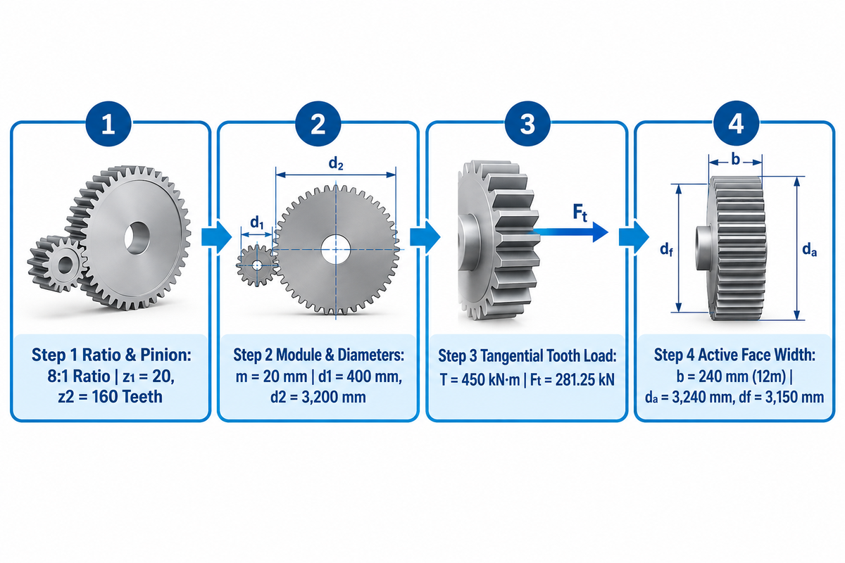
Sizing large diameter gears requires calculating pitch diameter (d = m × z), outside diameter (da = d + 2m), root diameter (df = d – 2.5m), and tangential tooth force (Ft = 2,000 × T / d). Engineers employ a 1.5x to 2.5x application safety factor alongside these geometry formulas.
Closed-form equations for pitch and root diameter establish geometric limits only. Closed-form pitch and root diameter equations establish geometric envelopes only, whereas final tooth root bending and flank contact stress ratings require full service-factor and load-distribution analyses. In metric gear sets, module (m, in millimeters) is the ratio of pitch diameter to number of teeth. As shown in KHK’s practical spur gear design procedure, multiplying module m by tooth count z establishes the exact reference circle where two mating gears transfer torque.
For dynamic load screening, Okdor’s spur gear sizing engineering guide notes that servo systems generate 1.5 to 2 times rated torque during acceleration, and hard stops can triple instantaneous loads. Okdor specifies a minimum 1.5x safety factor for steady loads and 1.5x to 2.5x safety margins across dynamic applications. At Aubrik, complete rotary systems are sized to an application factor of 1.65 for wind yaw drives or 2.0 for hydraulic shovels, with flank tolerances verified to ISO 1328-1:2013.
4-Step Module-to-Pitch-Diameter Sizer
Engineers perform the 4-Step Module-to-Pitch-Diameter Sizer to convert shaft torque and speed reduction requirements to verifiable gear parameters:
- Step 1 – Fix Gear Ratio and Pinion Teeth: Set the required reduction ratio (i = z2/z1). Choose a hardened pinion tooth count between z1 = 17 and z1 = 25 to avoid involute undercutting at a 20° pressure angle.
- Step 2, Select Module and Compute Diameters:
Select a standard heavy module (m = 10 to m = 55). Calculate pitch diameter d = m × z, outer diameter da = d + 2m, root diameter df = d – 2.5m, and circular gear pitch p = π × m, per KHK Table 4.1. - Step 3, Calculate Tangential Tooth Force:
Convert design output torque T (in N·m) into tangential force at the pitch circle using Ft = (2,000 × T) / d (with d in mm). For high-inertia drums use an application safety factor of 1.65 to 2.0. - Step 4, Set Face Width to Pitch Ratio: For Size, set face width b between 8m and 16m (typically 10m to 12m on open girth gears). Keep face-width-to-pinion diameter ratio (b / d1) below 1.2 for spur gears to avoid edge loading.
Worked Example, Illustrative Screening of a 3,200 mm Pitch Diameter Girth Gear: Consider an illustrative rotary drum drive requiring an 8:1 gear ratio and 450 kN·m of continuous ring torque. Selecting a 20-tooth forged pinion (z1 = 20) sets the girth gear tooth count at z2 = 160 teeth. Choosing module m = 20 mm yields a pinion pitch diameter of d1 = 400 mm and a main gear pitch diameter of d2 = 20 × 160 = 3,200 mm. The outside diameter is da = 3,200 + 2(20) = 3,240 mm, and the root diameter is df = 3,200 – 2.5(20) = 3,150 mm. At 450 kN·m torque, nominal tangential tooth load is Ft = 281.25 kN. Specifying a 12m face width (b = 240 mm) distributes the load evenly across the flank. Engineers sizing synchronized roller drives can compare this workflow with our guide on heavy-duty welding rotator torque and gear drive calculations.
| Gear Parameter | Formula (KHK Table 4.1) | Drive Pinion (z1 = 20) | Large Ring Gear (z2 = 160) |
|---|---|---|---|
| Normal Module (m) | Selected size based on bending load | 20 mm | 20 mm |
| Pitch Diameter (d) | d = m × z | 400 mm | 3,200 mm |
| Outside Diameter (da) | da = d + 2m | 440 mm | 3,240 mm |
| Root Diameter (df) | df = d – 2.5m | 350 mm | 3,150 mm |
| Active Face Width (b) | b = 12 × m (pinion +15 mm overhang) | 255 mm | 240 mm |
| Tangential Tooth Load (Ft) | Ft = 2,000 × T / d | 281.25 kN | 281.25 kN |
How Do Gear Modules and Pitch Diameter Affect Strength and Durability?
Gear module and pitch diameter govern tooth strength and pitting durability through two separate mechanical levers. As documented by Gear Solutions, the tooth root chord sFn at the 30° tangent to the root fillet determines tooth root bending strength. According to Okdor, a compact 40 mm gear with module 2.0 can outlast a 60 mm gear with module 1.0 under the same load because the larger module thickens the root chord.
An increase in the pitch diameter at a fixed shaft torque decreases the tangential force Ft on the gear teeth. With a greater pitch circle, the radius of curvature along the involute tooth profile also increases, and a greater contact band reduces surface contact stress and supports transmission efficiency throughout a 20-year operating life. For example, Aubrik 5 MW wind yaw ring gears are exposed to 1,000 to 3,000 kN·m load cycles in 20 years.
Monolithic Forged Rings vs. Segmented Girth Gears: Split-Joint Preload and Transport Limits
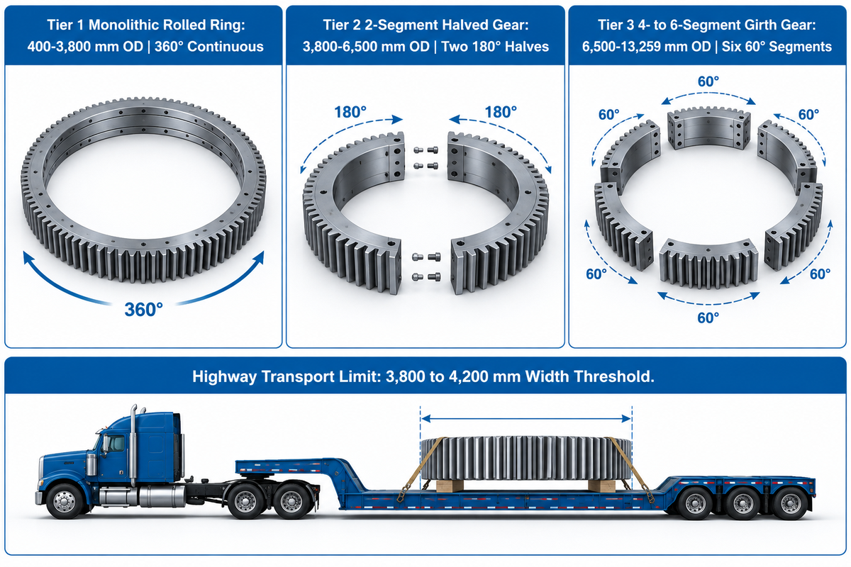
Transition from a monolithic one-piece forged ring to a two-piece or multi-segment bolted girth gear when the outside diameter exceeds highway shipping limits of 3,800 to 4,200 mm. Segmented rings are also justified if field replacement isn’t permitted to remove mill bearings or if segmenting reduces furnace distortion.
Over-the-road transport width limits, typically 3,800 to 4,200 mm without special police escorts, vary by regional highway jurisdiction and port clearance corridors. Up to roughly 3,800 mm outside diameter, a one-piece rolled forging is the most rigid solution. It eliminates split-line machining and maintains uniform hoop stress around the circumference.
Beyond 4,000 mm diameter, or whenever a ring gear must wrap around an existing rotary drum without lifting the trunnion bearings, segmented designs take over. In US Patent Application US20200124155A1 (Girth Gear), ring gear segments are joined by two flanges which are, in turn, fully penetration welded to the rim and the web and are stiffened by gussets. US Patent US6851485B2 discloses a ring gear which is segmented into 60 degree sections and is attached to a 360 degree frame. Each section uses one bolt and six fixtures to respond to shear loads.
In a simple gear train driving a horizontal kiln, the split seam passes through the pinion mesh once per revolution. It’s noted in Yile Machinery’s girth gear and pinion alignment guide that a failure to align the rings results in excessive vibration and tooth root failure. Whereas small catalog gears come off the shelf and gears usually slide onto a keyed shaft, segmented rings use precision shear dowels and high-preload flange bolts.
3-Tier Split-Ring Transport & Preload Matrix
Use the 3-Tier Split-Ring Transport and Preload Matrix below to match ring diameter, transport constraints, and joint fastener engineering.
| Design Tier | Outside Diameter Envelope | Logistics & Field Assembly | Split-Joint Fastening & Preload Rule |
|---|---|---|---|
| Tier 1: Monolithic Rolled Ring | 400–3,800 mm OD | Ships flat in standard container or flatbed; requires shaft-end mounting | No split seam; 360° continuous flange bolting or interference shrink fit on gear shafts |
| Tier 2: 2-Segment Halved Gear | 3,800–6,500 mm OD | Two 180° halves bypass 4.0 m highway width limits and install around existing shafts | Full-penetration welded joining flanges per US20200124155A1; reamed shear dowels + high-preload tension bolts |
| Tier 3: 4- to 6-Segment Girth Gear | 6,500–13,259 mm OD (or furnace-limited rings) | 90° or 60° segments fit standard 40 ft containers and smaller heat-treat furnaces | Six 60° segments with positioning bolts and six shear fixtures per US6851485B2; finish-cut as a full 360° ring |
Metallurgy and Heat Treatment: Forged Alloy Steels, Carburizing, and Induction Hardening
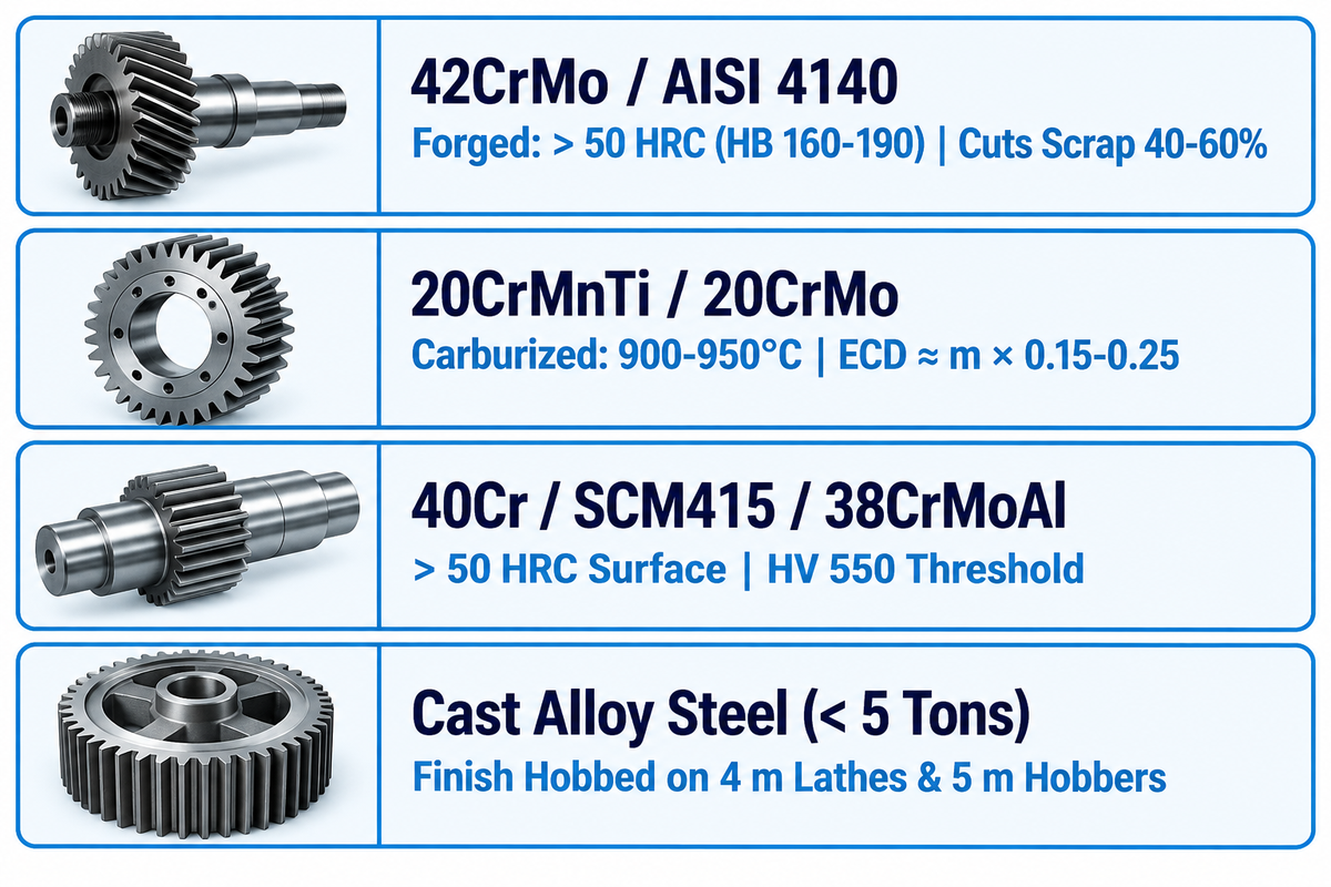
Large diameter gears are predominantly made using forged alloy steels including 42CrMo (AISI 4140), 40Cr, and 20CrMnTi. Hard-faced gear drives require tooth surface hardness above 50 HRC, pairing carburized case depths of 0.15m to 0.25m or closed-loop induction hardening to control thermal quench distortion.
Full-ring case carburizing above 2,000 mm diameter requires post-quench CNC form grinding to correct thermal ovality, so buyers without a grinding budget should specify tooth-by-tooth induction hardening instead. According to HY Forgings, gear refurbishment projects show that the greatest source of distortion, and therefore failure, occurs during heat treatment.
Many buyers assume that specifying maximum carburized hardness always extends gear life. However, Geyon Tech’s metallurgical analysis of gear heat treatment notes that hard-faced drives require surface hardness above 50 HRC. Their engineering rule of thumb sets effective case depth (measured to HV 550) at ECD ≈ module m × (0.15 to 0.25). Carburizing penetrates at 900 to 950°C before quench cooling. On rings above 2,000 mm diameter, full-furnace oil quenching at those temperatures introduces ovality that requires leaving a 0.2 to 0.4 mm grinding allowance.
On the other hand, Patsnap Eureka’s induction heat-treatment engineering review shows that closed-loop induction systems with non-contact pyrometry (<10 ms response time) reduce scrap rates by 40% to 60% and eliminate post-process rework. In Thermal Processing’s survey of Inductive Gear Hardening, tooth-by-tooth or dual-frequency induction hardening, heats the tooth flank and root only, keeping the quenched-and-tempered 42CrMo core cool. For corrosive environments, smaller gears are also available in stainless steel. Heavier fabricated gear blanks rely on our stress-relief services of heavy CNC machining and fabricated steel blanks.
How Do Material and Heat Treatment Choices Impact the Required Gear Size?
Material selection and heat treatment directly govern allowable contact fatigue strength and tooth-root bending strength, which determines how compact a gear set can be for a given torque. As documented in Okdor’s gear material testing, upgrading from untreated carbon steel to heat-treated 4140 (42CrMo) or carburized alloy steel increases allowable tooth bending stress by 2 to 3 times. Consequently, an engineer can reduce the required pitch diameter and face width while transmitting the same torque load capacity.
| Alloy Grade | Heat Treatment Route | Hardness & Core Baseline | Effective Case Depth Rule | Distortion & Finishing Allowance |
|---|---|---|---|---|
| 42CrMo / AISI 4140 Forged | Normalizing / Q&T + scanning induction hardening | > 50 HRC flank (HB 160–190 pre-turn baseline) | Defined to HV 550 cutoff along flank and root | Closed-loop pyrometry cuts scrap 40–60%; minimal ovality |
| 20CrMnTi / 20CrMo Alloy | 900–950°C gas carburizing + oil quench + temper | > 50 HRC hard-faced drive rating | ECD ≈ m × 0.15–0.25 (0.8–1.5 mm on medium modules) | Leave 0.2–0.4 mm+ grinding stock for post-quench CNC form grinding |
| 40Cr / SCM415 / 38CrMoAl | Quenched & tempered + surface nitriding or induction | > 50 HRC surface with tough alloy core | Verified to HV 550 threshold on heat-treat drawing | Low thermal distortion; suited for precision ring gears |
| Cast Alloy Steel (< 5 Tons) | Normalized, quenched, and stress-relieved | Through-hardened machinable ring blank | Through-section hardness across tooth and rim | Finish hobbed on 4 m vertical lathes and 5 m gear hobbers |
CNC Machining Workflows: Gashing, Hobbing, Hard Skiving, and Profile Grinding
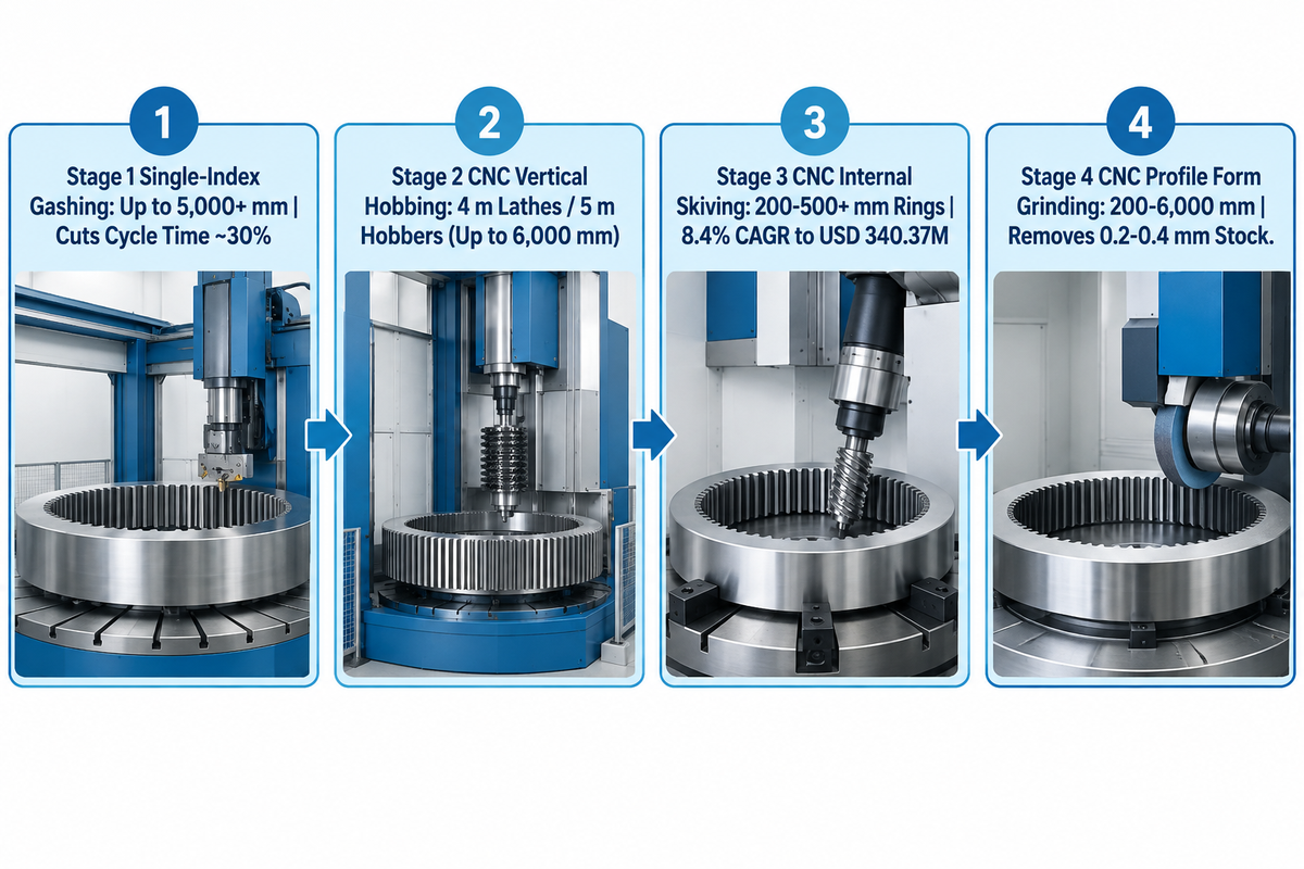
In the case of large module gears, the machining is done in several stages using CNC lathes. Shops start with rough turning on a 4-meter vertical lathe and rough gashing or dry-cutting to reduce cycle time by 30%. Final geometry comes from 5-meter CNC vertical hobbing, heat treatment, hard skiving, and profile grinding.
Chattering and rapid tool wear are issues during the CNC hobbing of large-module gears from a forged ring. Matching the indexing method of the blank to the gear is emphasized by experienced machinists and a technical editor from Practical Machinist’s heavy gear hobbing forum and a technical editor from Gear Solutions, respectively. Small cutter diameters also yield up to 15% higher root strength by keeping the contact pattern centered.
Multi-axis CNC machine tools have transformed hard finishing for precision gears. According to a 2026 peer-reviewed study in Mechanics & Industry, since the early 2000s multi-axis machining has enabled producing gear teeth on universal CNC machines while precision classes tighten under ISO 1328-1.
For internal ring gears where slow reciprocating shaping was once the only option, power skiving now dominates. Straits Research reports that the global internal gear skiving machine market was valued at USD 164.7 million in 2025. It’s projected to grow from USD 178.53 million in 2026 to USD 340.37 million by 2034 at an 8.4% CAGR. Leaving a 0.2 to 0.4 mm grinding allowance before heat treatment lets CNC profile grinding deliver smooth operation under peak loads.
| Machining Process | Verified Machine Envelope | Module / Size Range | Standard & Stock Allowance | Key Engineering Advantage |
|---|---|---|---|---|
| Single-Index Face Milling / Gashing | Up to 5,000+ mm ring blanks | m 10–55 heavy modules | Leaves 0.2–0.4 mm+ finishing stock | Dry-cutting cuts cycle time ~30% vs. five-cut wet method |
| Heavy CNC Vertical Hobbing | 4 m vertical lathes / 5 m hobbers (up to 6,000 mm at Aubrik) | m 10–55 external gears | ISO 1328-1:2013 / DIN 3962 / AGMA 2000 | Continuous indexing for large external spur and helical rings |
| CNC Internal Gear Skiving | 200–500 mm medium & 500+ mm large internal rings | Internal & planetary ring gears | 54.63% vertical skiving machine share (8.4% CAGR) | Replaces slow reciprocating shaping on hardened internal teeth |
| CNC Profile Form Grinding | 200–6,000 mm custom rotary rings | Hard-faced drives (> 50 HRC) | Removes 0.2–0.4 mm heat-treat distortion stock | Restores involute profile and lead crowning after carburizing |
Quality Assurance, ISO 1328 and AGMA 2015 Accuracy Grades, and NDT Acceptance
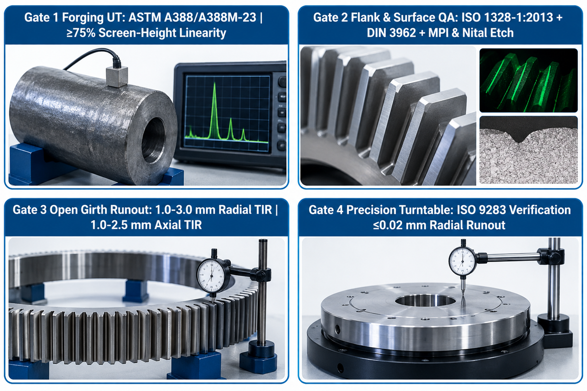
Large diameter gears require pulse-echo ultrasonic testing of forged blanks as part of quality assurance, per ASTM A388/A388M, before tooth cutting and magnetic particle inspection after hardening. The final runout measurements hold 1.0-3.0 mm TIR on open girth gears and ≤0.02 mm on precision turntables.
Discovering subsurface forging discontinuities after CNC hobbing and form grinding leads to the entire ring blank being scrapped. When assessing gear quality and defining purchase order gear requirements, engineers mandate three NDT and metrology gates prior to shipment.
Prior to rough gashing, all one-piece rolled rings and open-die forgings must pass volumetric ultrasonic testing. The ultrasonic testing is in conformance to the ASTM A388/A388M-23 International Forging Inspection Standards and Infinita Lab’s ASTM A388 Ultrasonic Testing Protocol. Contact pulse-echo straight-beam and angle-beam scans use pulsed reflection units, with the signal presented in a linear format over at least 75% of the screen height. This type of scan is performed to identify discontinuities before the forging is put into service.
Second, tooth flank deviations are verified against ISO 1328-1:2013 and DIN 3962 or AGMA 2000 tolerances. According to Yile Machinery’s alignment specification, acceptable field radial runout for large open girth gears is 1.0 to 3.0 mm total indicator reading (TIR). Acceptable axial face runout is 1.0 to 2.5 mm TIR. Third, on precision rotary welding turntables, Aubrik performs ISO 9283 verification to hold ≤0.02 mm radial runout. Maintenance teams can review full inspection sheets in our guide to industrial gear maintenance, inspection, and repair procedures.
Do
- Require contact pulse-echo ultrasonic testing per ASTM A388/A388M (≥75% screen-height linearity) on the forged blank before cutting teeth.
- Perform magnetic particle inspection (MPI) and Nital acid etch testing after profile grinding to rule out temper burn.
- Verify radial runout (1.0–3.0 mm TIR on open girth gears; ≤0.02 mm on precision turntables) and recheck contact after 24–48 hours under load.
Don’t
- Accept hardness readings taken only on the outer rim face instead of verifying effective case depth to HV 550 along the tooth flank.
- Unclamp a multi-segment girth gear before match-marking each flange and verifying positioning bolt and shear fixture alignment.
- Operate an open girth gear with tooth contact covering less than 70% of the active tooth flank area.
Heavy-Duty Applications, Alignment, Lubrication, and Rotary Welding Positioner Drives
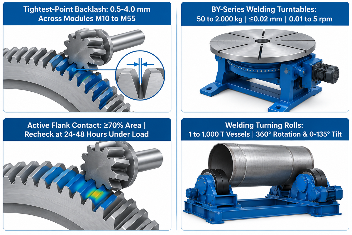
Service life in ball mills, rotary kilns, and heavy welding positioners depends on holding pinion-to-gear contact across at least 70% of the active tooth flank area. Technicians set tightest-point backlash to 0.5–4.0 mm across modules M10 to M55 and check alignment every 12–24 months.
Even a precision-ground ring gear will fail prematurely if field alignment or lubrication breaks down. Based on Yile Machinery’s girth gear alignment guide, contact of the tightest point at the flank is set to a backlash of 0.5-4.0 mm on modules between M10 and M55. The contact pattern must cover at least 70% of the active tooth flank area. Engineers recheck contact after the first 24 to 48 hours under load and inspect alignment every 12 to 24 months during planned shutdowns.
In enclosed gearboxes, positive-displacement gear pumps circulate filtered oil across the mesh, while open girth gears use automated intermittent spray lubrication. In automated fabrication shops, hardened slewing ring gears and alloy reducers drive heavy welding positioners and rolls. According to Aubrik’s BY-Series welding turntable specifications, six standard models cover 50 to 2,000 kg loads (custom 5,000+ kg) with ≤0.02 mm runout and 0.01 to 5 rpm stepless speed. For larger drums, Aubrik welding rotators and turning rolls can handle 1 to 1,000 T cylindrical vessels.
Because gears can be used in both 360° continuous rotation and 0–135° cantilevered tilting, frame rigidity and backlash control directly govern weld seam tracking. Heavy rotary table integrators can consult our guides on large welding positioner slewing ring drives for oversize weldments and precision rotary welding turntable gear backlash control.
Should I Worry About Gear Noise, and Does Size Affect How Loud They Are?
Yes, irregular gear noise is an early mechanical sign of pitch-line runout, shaft misalignment, or breakdown of the lubricant film, and gear size amplifies sound pressure. At a particular RPM, an increase in pitch diameter leads to a higher peripheral velocity, thus a greater impact velocity. As shown in Mechanics & Industry (2026), high peripheral speeds require tight control of transmission error and vibration. Transitioning from straight spur teeth to helical or double helical teeth and verifying ≥70% flank contact area reduces noise from heavy drives.
Sourcing Custom Large Gears: Lead-Time Bottlenecks, Cost Drivers, and 2026 Industry Outlook
Obtaining large custom gears requires balancing blank volume against lifetime operating costs. According to Aubrik and Okdor engineering data, initial purchase price represents only 20–40% of a gear’s true lifetime cost, while oversizing a gear by 50% doubles material and machining expense.
Quoted delivery times are constrained by forged ring-rolling mills, heat-treatment furnaces, and ultrasonic inspection. According to Aubrik’s industrial gear portal, the purchase price of a gear typically represents only 20% to 40% of its true lifetime cost, while the rest is unplanned downtime, maintenance, and rework. However, Okdor’s cost-scaling analysis shows that a 50% oversizing of a gear can double the cost due to a cubic increase in material and machining.
Across 2026 and beyond, three manufacturing shifts are reshaping how buyers specify custom gears. First, as reported in Mechanics & Industry (2026), industrial transmissions are adopting multi-axis machining and tighter ISO 1328-1 accuracy classes to raise power density. Second, CNC internal gear skiving (growing at an 8.4% CAGR to USD 340.37 million by 2034 per Straits Research) is replacing slow shaping on internal ring gears. Third, closed-loop induction hardening is cutting heat-treat scrap by 40% to 60%.
To avoid delays in engineering clarifications, include all the parameters in the checklist below when submitting your drawings to custom industrial gear and ring gear manufacturing companies.
Engineering RFQ Specification Checklist for Custom Large Diameter Gears
| Specification Category | Mandatory Drawing & RFQ Inputs | Verification Standard / Target |
|---|---|---|
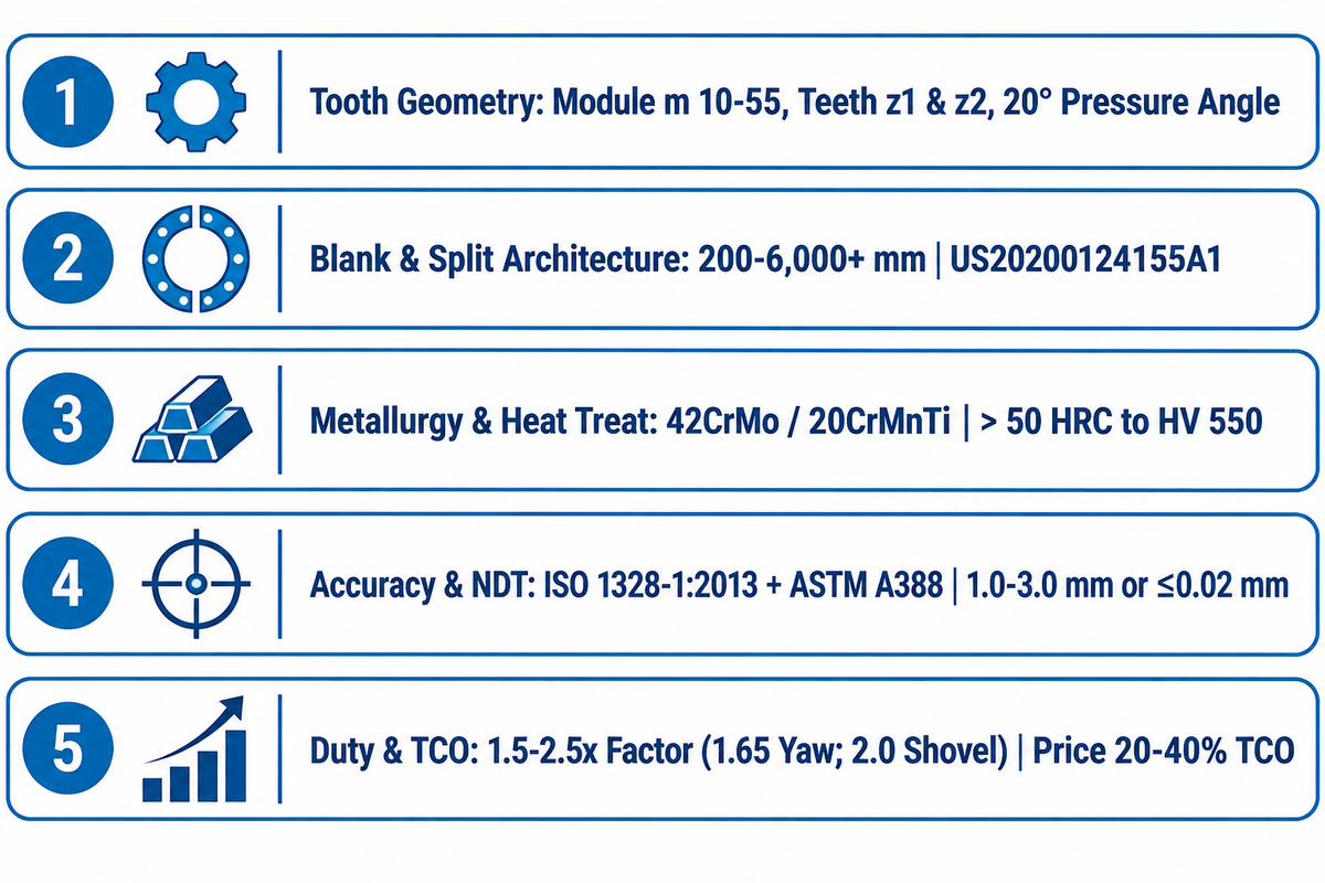
| 1. Tooth Geometry | Normal module (m 10–55), number of teeth (z1, z2), pressure angle (20°), helix angle & hand, profile shift coefficient (x) | KHK Table 4.1 / ISO 1328-1:2013 geometry sheet |
| 2. Blank & Split Architecture | Pitch/outside/root diameters (200–6,000+ mm), face width (b), datum bore tolerance, 1-piece vs. segmented flange layout | US20200124155A1 / US6851485B2 split-joint spec |
| 3. Metallurgy & Heat Treat | Forged grade (42CrMo, 40Cr, 20CrMnTi), pre-turn HB 160–190, flank hardness (> 50 HRC), effective case depth to HV 550 | ECD ≈ m × 0.15–0.25 + 0.2–0.4 mm grind stock |
| 4. Accuracy & NDT Package | Flank tolerance class, radial/face runout TIR (1.0–3.0 mm girth; ≤0.02 mm turntable), ultrasonic testing & MPI | ISO 1328-1:2013 + DIN 3962 + ASTM A388/A388M |
| 5. Operating Duty & Factor | Motor kW, input/output RPM, nominal & peak shock torque (1.5–2x acceleration), target application factor | Application factor 1.5–2.5x (1.65 wind yaw; 2.0 shovel) |
Key takeaway
Pair hard-faced alloy steel (> 50 HRC) with ASTM A388 ultrasonic forging inspection and a 1.5x to 2.5x safety factor. That combination prevents quench distortion and tooth root failure on large diameter gears.
Need Custom Large Diameter Gears or Heavy Rotary Drive Assemblies?
Share your gear drawing, module specification, or rotary load envelope with our engineering team. You can request a custom gear machining quote and DFM review from Aubrik Company (200–6,000 mm gear capability, ISO 9283 ≤0.02 mm turntable runout, and 1–1,000 T turning roll systems).
Frequently Asked Questions About Large Diameter Gears
Can different gear types be mixed in the same gearbox?
Multi-stage industrial gearboxes commonly integrate various gear types across sequential shafts to balance torque density and shaft orientation.
Subsequent stages use single helical or double helical gears on parallel shafts to multiply low-speed output torque while controlling axial bearing thrust.
Does face width significantly influence load capacity and lifespan?
Increasing face width directly increases root bending capacity and tooth flank pitting resistance since the load is spread over a larger contact area.
Under DIN 3962 and AGMA 2000 alignment tolerances, increasing the face-width-to-pinion-diameter ratio beyond 1.2 for spur gears or 2.0 for double helical gears brings diminishing returns. Pushing these ratios further leads to shaft deflection, which causes edge loading. To prevent this, helix lead crowning has to be ground into the teeth.
What happens if I oversize a spur gear in a heavy industrial drive?
Oversizing a spur gear increases rotational inertia, pitch-line velocity, forging blank weight, and housing footprint without necessarily improving service life.
According to Okdor’s engineering cost data, a gear that is 50% oversized can double material and machining costs due to the cubic volume relationship. Higher peripheral speed also raises dynamic tooth-meshing impact forces, requiring tighter ISO 1328 profile grinding tolerances and larger motor starting torque.
Can helical gears be used on non-parallel shafts?
Yes, when configured as a crossed helical gear pair (also called a screw gear), two helical gears connect motion between non-parallel, non-intersecting shafts.
Because crossed helical gears mesh in point contact with high sliding friction, their load capacity is very low. For high-torque large diameter drives on non-parallel shafts, engineers specify spiral bevel or worm gears instead.
Where are large diameter gears typically made and forged?
Large diameter gears are forged and cut in large industrial centers in the United States, Germany, Japan and China (like Wuxi and Luoyang). These centers operate 4-meter to 6-meter ring rolling mills and vertical CNC hobbing machines.
What happens if I get the gear size wrong, can I fix it without redesigning the entire housing?
Yes, when the center distance is fixed by an existing housing, engineers correct minor ratio or tooth-strength issues using profile shift.
As shown in KHK Table 4.3, the application of the positive profile shift (+x1) to the pinion and matching modification to the ring gear cause the tooth root to thicken without moving the bearings. Gear Solutions reports that using a smaller cutter diameter can increase root strength by up to 15%. Adjusting the normal module and helix angle together would keep the operating pitch diameters the same. When only the pinion is worn, the fastest solution before replacing the bull gear is to use a custom profile-shifted pinion replacement.
When are large diameter plastic gears viable instead of forged steel?
Large diameter cast nylon or acetal segment gears can be used in light chemical or washdown drums where corrosion resistance and self-lubrication outweigh bending strength. For high-torque industrial drives, forged 42CrMo or 20CrMnTi alloy steels, hardened to above 50 HRC remain mandatory.
About This Engineering Guide: Reviewed by the Aubrik Company technical team (lead author: CYH). Compiled using ISO 1328-1:2013 flank tolerance standards, ASTM A388 ultrasonic forging specifications, and Aubrik rotary drive test logs.
References & Sources
- ISO 1328-1:2013 Cylindrical Gears, ISO System of Flank Tolerance Classification (TC 60) International Organization for Standardization (ISO)
- ASTM A388/A388M-23 Standard Practice for Ultrasonic Examination of Steel Forgings ASTM International / iTeh Standards
- Gear Power Transmissions in 2026: Current Challenges and Future Perspectives Mechanics & Industry (EDP Sciences, 2026)
- US20200124155A1: Segmented Girth Gear Assembly and Flange Fastening United States Patent and Trademark Office / Google Patents
- US6851485B2: Ring Gear Segment Positioning and Shear Load Distribution United States Patent and Trademark Office / Google Patents
- Gear Technical Reference: Calculation of Gear Dimensions (Tables 4.1–4.9) Kohara Gear Industry Co., Ltd. (KHK Stock Gears)
- Girth Gear and Pinion Alignment Guide: Runout, Backlash, and Contact Pattern Luoyang Yile Machinery Co., Ltd.