Get in Touch with Aubrik Company

Updated July 2026.
A robotic welding cell is an integrated automated welding cell consisting of a welding robot, power supply, positioner, safety enclosure and controller to weld parts with the same accuracy every time. Buyers usually hit the same stumbling block when they go to evaluate one: “robotic welding cell,” “robot,” “welding system,” and “cobot cell” are often used interchangeably, and it’s often unclear on vendor pages which configuration fits a particular output rate.
Quick Specs
| Cell Types | Fixed workbench, single-axis tilt, single-axis turntable, two-axis, cobot |
| Robot Reach / Payload | 1.4–2.0 m reach, 6–20 kg torch payload (6-axis arm) |
| Welding Processes | MIG/MAG (GMAW), TIG (GTAW), FCAW, laser, spot |
| Typical Install Time | 3–5 days mechanical (pre-engineered) + 1–2 weeks commissioning |
| Governing Standards | ANSI/A3 R15.06-2025, ISO 10218-1/2:2025, AWS Z49.1, AWS D16.1 |
This guide unpacks the terminology, actual parts, cobot vs traditional trade-offs, welding-process compatibility, fixturing, vendor landscape, economics, procurement, safety standards, programming, and future trends in 2026 – with every data point sourced to an external party and not a vendor’s webpage. The advantages of robotic welding show up unevenly depending on your part mix, so this guide leads with the trade-offs, not the sales pitch.
In this guide
- What’s a cell, and how does it compare to a bare arm, a whole production line, or a cobot cell
- Why the robot brand matter less than integration quality
- Cobot vs. traditional cell selection, with real cost bands
- Economics – and the one situation in which it’s disadvantageous for automation
- What to look for in the 2025 safety-standard update
What Is a Robotic Welding Cell, The Four-Way Terminology Split
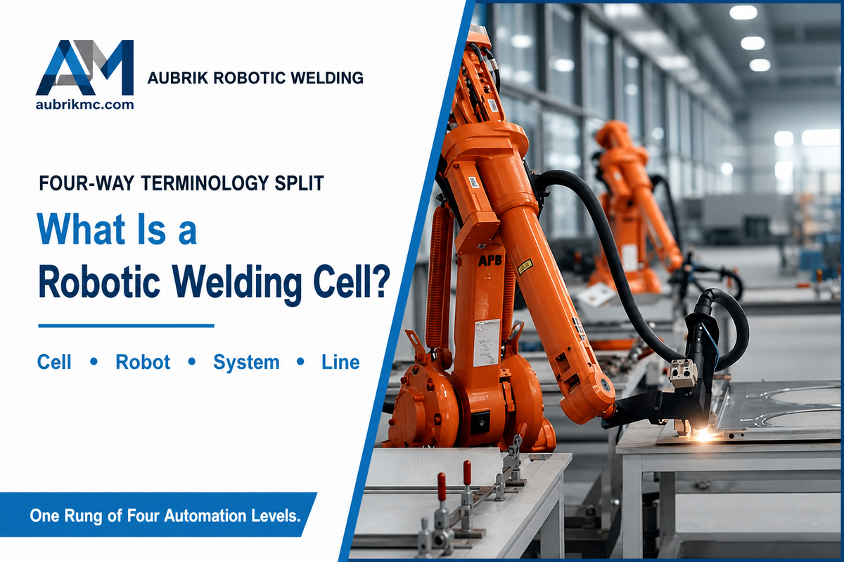
A robotic welding cell integrates a robot arm, welding power supply, positioner, safety enclosure, and controller in a self-contained work envelope where the robot will perform a programmed weld trajectory without anyone within the arm’s range of motion. That same component list — power source, positioner, and controller integrated as one networked system — shows up in the welding-industry’s own device-level integration standards, not just vendor marketing copy. Fabricators purchase the cell, not just the robot inside it.
When Searching for this topic, searchers often group four tightly related phrases together-robotic welding cell, robot welding cell, robotic welder, and robotic welding system-effectively representing one search interest. However, no two terms have exactly the same meaning from an engineer’s point of view when looking at a quote. Grouping them can prevent costly ordering errors early in the process.
| Configuration Type | What It Is | Typical Footprint / Capacity | Best For |
|---|---|---|---|
| Robot / robotic arm (bare) | 6-axis manipulator alone — no power source, fixturing, or guarding | 1.4–2.0 m reach, 6–20 kg payload | Not a purchasable production unit on its own |
| Fixed workbench cell | Stationary work platforms, no positioner rotation | ~3 m × 4 m (~130 sq ft) | Small-scale entry point, simple repeatable joints |
| Single-axis tilt cell | 1–2 head-tail positioners, up to ~300 kg | ~3 m × 4 m | High-mix shops needing rotation or tilt |
| Single-axis turntable cell | Horizontal rotating table, up to ~500 kg | ~3 m × 4 m | Large workpieces, high-volume circumferential welds |
| Two-axis positioner cell | L-type dual-direction positioners, up to ~300 kg each | ~3 m × 4 m | Complex multi-angle, high-mix production |
| Cobot cell | Collaborative robot, reduced or no perimeter fencing | Smallest — often under 10 m² | High-mix, low-volume, frequent part changeover |
| Dual-station rotary cell | Two stations rotate 180° while the robot welds one side | ~20 m² (~215 sq ft) | Sub-3-minute cycle times, continuous high-volume runs |
| Robotic welding line / system | Multiple cells or stations tied together with material handling | Full production floor | Multi-station serial manufacturing |
| Track/gantry-mounted robot | Robot travels along a rail instead of sitting fixed in one cell | Extends to very large/irregular parts | Oversized weldments that do not fit inside a fixed cell |
One important thing to get out of the way upfront is that a fixed-size cell may not always be appropriate for a given workpiece. Track and gantry systems were designed for those parts that won’t fit into the confined space of a cell, such as long and heavy structural members, extremely irregularly shaped objects, and pieces that will be handled on the shop floor rather than placed into an enclosure.
📐 Engineering Note
Cell sizes typically run about 3 m by 4 m (130 sq ft) for a single station and closer to 20 m (215 sq ft) for a two-station rotary setup, and should be factored in before you start pricing the project.
Core Components & Cell Architecture, Fixed vs. Modular
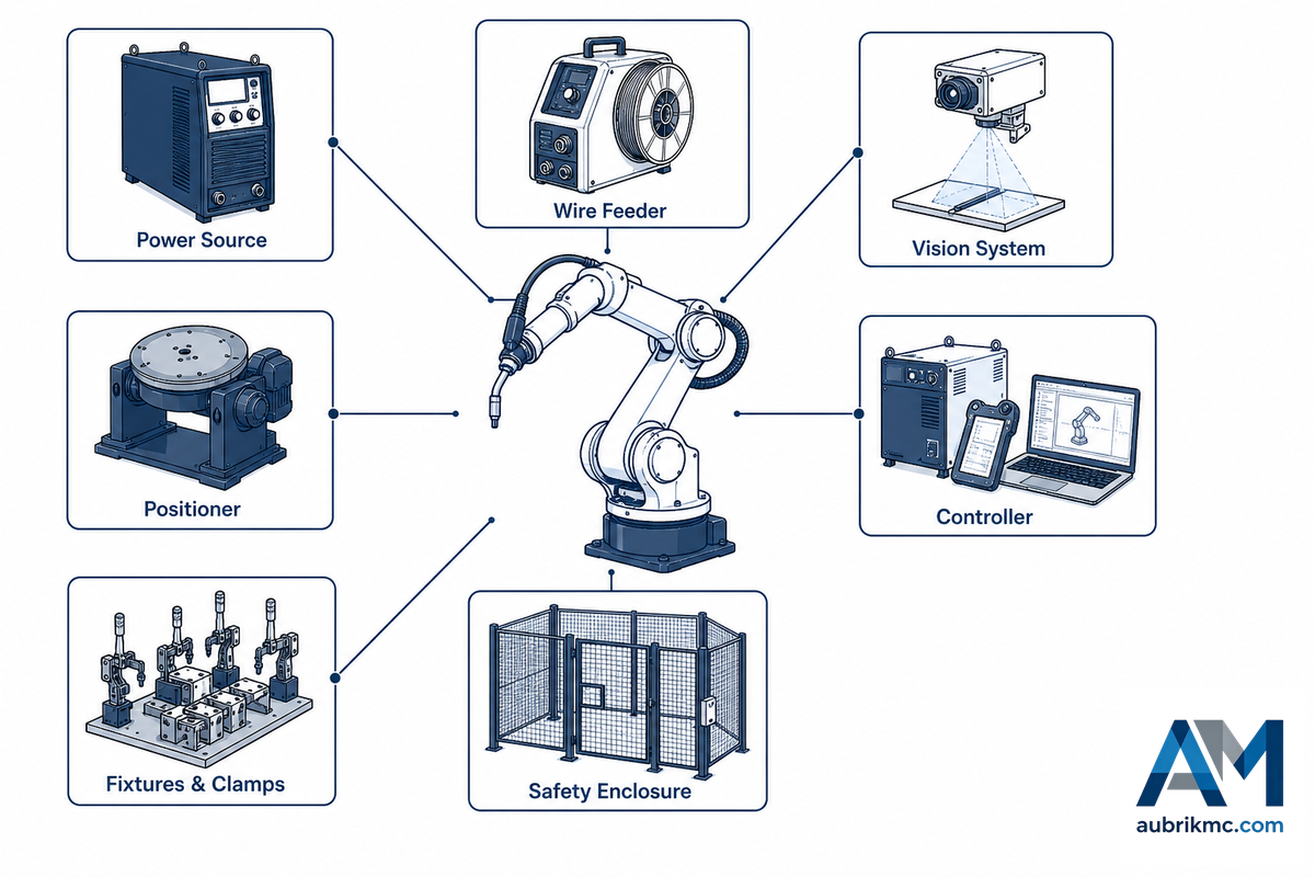
Regardless of manufacturer, any effective cell will incorporate the following eight components: 6-axis robot arm, welding power source, positioner, fixtures and clamps, controller and software, safety systems, wire feeder, and a vision system (often with a seam tracker) to track welds. Whether that adds up to a modular system or a fixed one determines how much the cell can absorb new welding applications later without a rebuild.
The Integration-Over-Iron Principle
The robot arm is the most commoditized component of the cell – any 6 axis arm from any reputable manufacturer can move a torch on a taught path. What actually drives cell performance in production is integration quality: whether the power source is constantly communicating joint parameters to the robot controller over a proper device-level network rather than a bolted-together workaround, whether fixturing is holding within tolerances that enable the robot to reliably find each joint, and whether the programming is sophisticated enough to accommodate real world part variation. A buyer comparing quotes on robot spec sheets alone is comparing the least consequential variable.
✔ Fixed Architecture
- Lower upfront cost for a single, unchanging part family
- Simpler to commission and validate
- No spare capacity for new joint geometries
⚠ Modular Architecture
- Higher initial cost for unused expansion capacity
- Accepts new positioners, tracks, or a second process later
- Avoids a full retrofit when production requirements shift
Does the Robot Brand Matter More Than the Integration?
View Answer
No. Setup any properly rated 6-axis arm on a table with a basic power source and no attention to fixturing, and the output will be an expensive fixture that passes muster in a demo and fails in production. What actually predicts success is whether the fixture holds the workpiece within tolerance, whether the power source can vary parameters mid-weld for joint variation, and whether the programming can be updated without a full re-teach. Successful shops don’t just compare robot brand and payload on a spec sheet — they budget for the integration work that determines whether the cell hits its throughput target.
Cobot Welding Cells vs. Traditional Robotic Cells, Which Fits Your Shop?
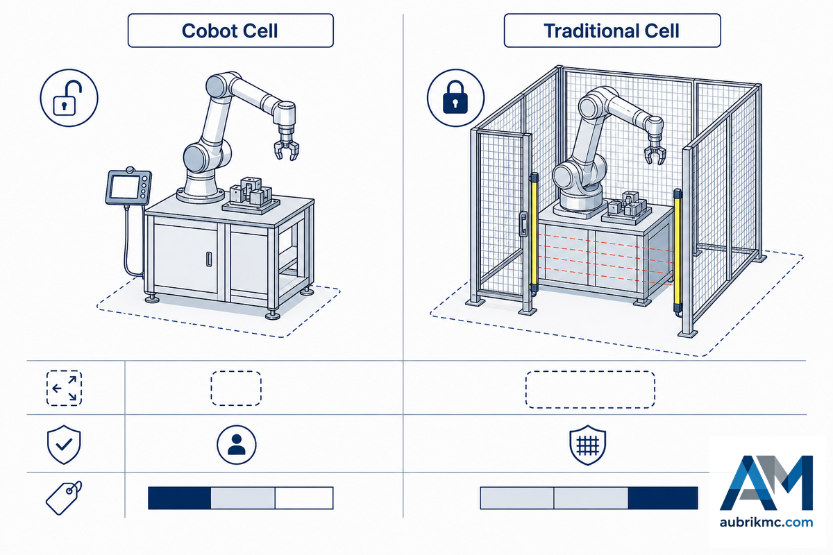
Collaborative versus traditional – not brand – is the first true fork in the selection process. A cobot welding cell runs a collaborative robot made to operate without perimeter fencing when built to ISO 10218-2 collaborative-operation standards; a traditional cell uses a full-power industrial arm that requires a full perimeter fence.
| Factor | Cobot Cell | Traditional Cell |
|---|---|---|
| Best for | High-mix, low-volume, frequent part changeover | Serial, high-volume production |
| Programming | Graphical / hand-guided, minutes per new part | Teach-pendant or offline, hours to days |
| Safety requirement | Reduced/no perimeter fencing (ISO 10218-2 + ISO/TS 15066) | Full perimeter fencing, light curtains, E-stops |
| Footprint | Smallest — often under 10 m² | ~12 m² single-station, ~20 m² dual-station |
| Typical price band | $50,000–$150,000 | $130,000–$250,000 (single station) |
One real-world trend militates against considering the traditional cell as the default “serious” alternative: companies that purchase a fully-guarded traditional cell to do very high mix, very low volume work often find they use it less – it sits idle during exactly the reprogramming windows a cobot would absorb in minutes — an expensive mismatch that shows up on the shop’s utilization report long before anyone re-examines the original purchase decision. That’s a structural difference, not a matter of vendor quality: a cobot’s ISO/TS 15066 collaborative-operation rating is what lets it skip the fencing and light-curtain installation that adds real cost and floor space to a traditional cell. Match architecture and volume first, then adjust for the mix.
Aubrik’s own cobot welding line is one example of a pre-integrated collaborative solution in this segment, along with the general vendor space below. Small and medium-sized fabricators tend to gravitate here first, since the lower entry cost and reduced fencing requirement make the first automation purchase less risky.
Matching the Welding Process to Your Application
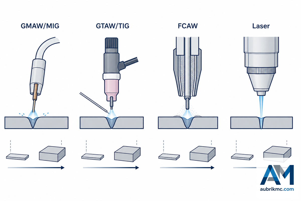
Most robotic arc welding systems default to GMAW/MIG due to its fast build rate and ease of automation, but other processes’ selection and application criteria come into play depending on type of material, material thickness, and joint quality requirements.
| Process | Best For |
|---|---|
| GMAW/MIG | Standard carbon steel below ~12 mm, highest build rate |
| GTAW/TIG | Stainless, aluminum, precision joints where appearance/quality matters |
| FCAW | Heavy plate, high deposition, less joint-fit sensitivity |
| Laser welding | Thin materials, minimal heat input, tight tolerance assemblies |
Materials thicker than around 20mm, or runs of stainless steel/ aluminum, frequently require pulsed MIG, TIG, or tandem wire operations rather than standard settings – each method alters the power source and torch type, so process selection should be finalized before power source pricing. Get this wrong and the failure mode is expensive and hard to see coming: a power source sized for standard GMAW on thin carbon steel will struggle with porosity and burn-through on 20mm-plus plate, and by the time that shows up in a failed weld inspection, the wrong power source is already bolted into the cell.
Plasma arc welding is a niche fifth option worth knowing about even though most cells never use it — it fits a narrow band of precision, low-heat-input applications that laser can’t always reach cost-effectively. Whichever process you land on, welding parameters (wire feed speed, voltage, travel speed) still have to be dialed in and held steady, and the welding torch itself needs routine attention: a clogged gas nozzle or worn contact tip is a common, avoidable cause of excess spatter and inconsistent arc starts on an otherwise correctly programmed cell.
Positioners, Turntables & Fixturing Inside the Cell
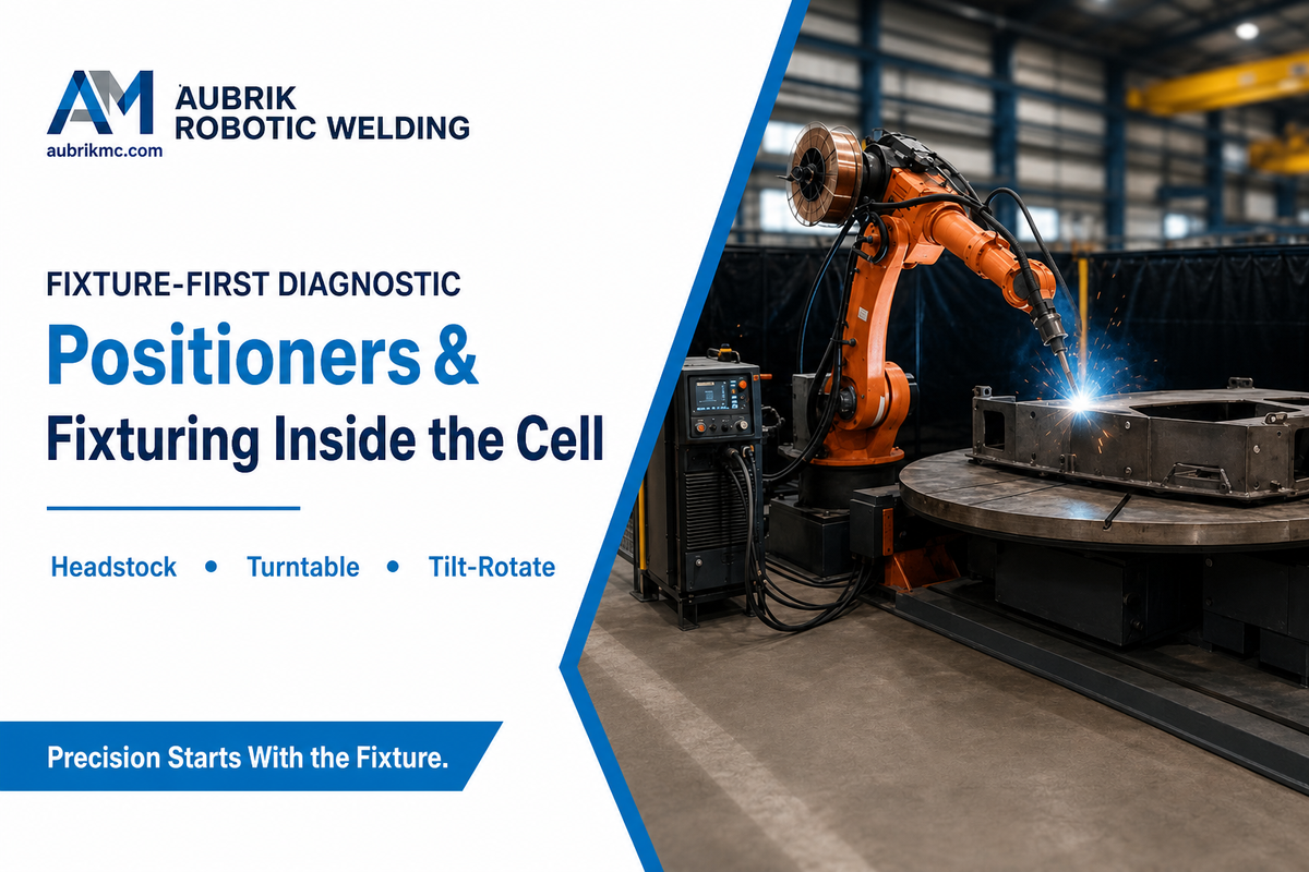
Fixturing and positioning are the usual culprits when a robotic welding cell project runs over budget and behind schedule, precisely because they’re commonly treated in the buying decision as an afterthought, no different from the robot itself. That’s a costly and avoidable mistake: a fixture that doesn’t hold tolerance is a hidden, recurring expense that resurfaces on every part run, not a one-time integration problem.
Positioner Types
- Headstock-and-tailstock positioners hold cylindrical or framed workpieces between two rotary chucks – suitable for pipe assemblies and beam sections, including heavy-duty large components that would otherwise need manual repositioning mid-weld.
- Single-axis servo turntables position flat workpieces for fillet welds around the entire perimeter.
- L- or H-shape tilt-rotate positioners introduce a third rotary axis for 3-dimensional welds, suitable for brackets and gusset plates.
This relationship of precision to tolerance is the most important and the most unexpected thing in the whole guide. The Fabricator states in no uncertain terms that the robot can only be made to produce a high quality weld when the parts are held to about half the tolerance of the weld wire diameter. ±0.05 mm (which is the typical repeatability of a 6-axis modern robot arm) isn’t a wide latitude for a fixture out of true and in fact more precision in the robot often makes the errors of a fixture more apparent rather than less so in the completed weld. As one welder posted on Reddit, “the machines are too precise – if the assembly or tolerances aren’t perfect you get bad welds.” A cell can only produce repeatable, precise welds when the fixture upstream of it holds its end of the tolerance bargain.
Can a Robotic Welding Cell Coordinate With a Positioner in Real Time?
Show Answer
Yes, for cells designed to do so, in a process called coordinated motion. On such cells, the robot controller synchronizes its torch-motion trajectory to the positioner’s rotation, so the weld remains in the flat (1G) orientation for the entire cycle, instead of the robot tracking a moving joint. All robot controllers are capable of coordinating with positioners out of the box if a part necessitates the simultaneous use of the robot and the positioner, but you need to be sure the controller supports coordinated-motion before ordering the part and not after installation.
For shops wanting a stand-alone version of this hardware as part of a fixturing solution and not a whole cell, Aubrik’s own equipment lines – welding positioners, welding rotators and turning rolls, and column-and-boom welding manipulators – also have products in the range.
The Pre-Engineered Cell Landscape, Fixed, Modular & Vendor Options
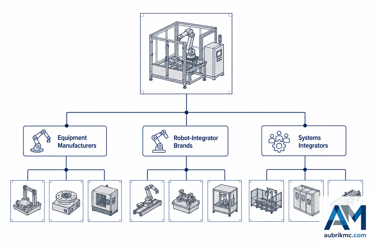
Vendors in the pre-engineered segment can be categorized as equipment manufacturers offering robotic welding solutions (e.g. Miller PerformArc, Lincoln Electric’s standard robotic cells, Fronius robotic packages); robot-integrator brands (e.g. Yaskawa Motoman’s ArcWorld, ABB); or niche and general systems integrators (e.g. THG Automation, Zhouxiang). Full-range manufacturers also build the cell alongside accompanying equipment such as positioners and manipulators. For example, Aubrik’s Q-Spark robotic welding cell line comes in four standard setups: fixed workbench, single-axis tilt, single-axis turntable, and two-axis positioner.
There’s no single format to beat all others, and the most expensive mistake buyers make in this segment is picking vendor category before part geometry. As one automation integrator publicly admitted, weld cells “aren’t always the ideal tool for handling real parts” — for bulky or irregularly shaped parts, the comparable systems were track-mounted or gantry robots, not a stationary cell at all. Compare your vendors against your part envelope first; the brand matters a lot less than the physical fit of the tool.
The practical split shows up by industry. Structural-steel fabricators and heavy-equipment OEMs welding beams, brackets, and oversized frames tend to need the reach of a gantry or track-mounted system precisely because a fixed cell’s work envelope caps out too early for their parts; job shops running smaller, high-mix production runs are usually better served by a fixed or positioner-based cell where changeover speed matters more than reach. Vendors that also manufacture in-house — rather than reselling a third-party arm bolted to a generic frame — can usually certify duty-cycle and repeatability figures for the whole cell, not just the robot, backed by ISO 9001 process records — figures worth asking for before signing a purchase order. A well-engineered, all-in-one cell built for high production runs should hold those figures steady shift after shift; a bolted-together generic frame with a high-performance robot dropped in rarely does.
The Economics, Arc-On Time, Downtime, and Payback
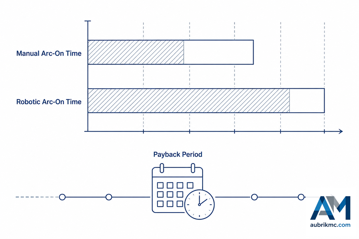
15–40%
Manual arc-on time
50–85%
Robotic arc-on time
12–24 mo
Industry-cited payback range
Four separate sources converge on the same directional gap: hand-operated welders run about 15-40% arc-on time per shift, while robotic cells push that to 50-85%. (Arc-on time means how much of a shift the torch is actually welding – a measure of machine uptime, not the machine’s electrical duty cycle, which is another matter altogether.) That gap is the whole reason for owning automation, because labor represents the biggest expense for a welding cell; the robot is still paid during changeover, but doesn’t fall victim to post-lunch fatigue. And that arc-on gap is the clearest evidence of an available improvement you can measure without investing a cent in new gear – give it a try at your own plant for a week before trusting what you read.
Worked ROI example: A shop runs one manual welder at a fully loaded $28/hour, two shifts a day. Automating that role with a cell running roughly 65% arc-on time versus the welder’s 25% recovers about 40 percentage points of productive time — call it 3.2 additional productive hours per 8-hour shift. Across two shifts and 250 working days a year, that’s about 1,600 recovered labor-hours, or roughly $44,800 a year in reallocated labor at that loaded rate alone, before counting rework and consumable savings. Calculate it against a $150,000 pre-engineered single-station cell, and that labor reallocation alone pays the cell back in about 3-4 years — a cost-effective automation process even before counting the throughput and quality gains layered on top. Commonly cited 12-24 month industry paybacks generally assume additional throughput and quality gains stacked on top of labor reallocation, not labor savings by itself — so run your own shift math rather than borrowing someone else’s payback number.
That said, the payback equation isn’t the same for everyone, and the academic record on this is more interesting than a single case study. Two 2024 Minnesota State University, Mankato theses from the same manufacturing-engineering program each compared robotic and manual welding on a different low-volume, high-mix part, and reached opposite conclusions. One study (Srinivasamurthy, 2024) found manual welding faster and less expensive for its test part, concluding “robotic welding isn’t always the answer,” even though the robotic cell still produced more parts per day on pure throughput. The other study (Mysore, 2024), on a different part from the same course, found robotic welding roughly 30% more cost-efficient for an equivalent working time per day. Read together, the two studies make the point better than either one alone: the answer genuinely depends on the specific part, not on a rule of thumb. If you’re truly low-volume, high-mix, do the math with your own part numbers on arc-on time and cost before assuming automation wins, because it doesn’t always, and sometimes it wins by more than you’d expect.
“The panelists agreed that robotic welders can be faster than manual operators with the welding process — but the main advantage is consistency, not raw speed.”
Procurement, Cost Drivers, Lead Time, and the Fixture-First Diagnostic Worksheet
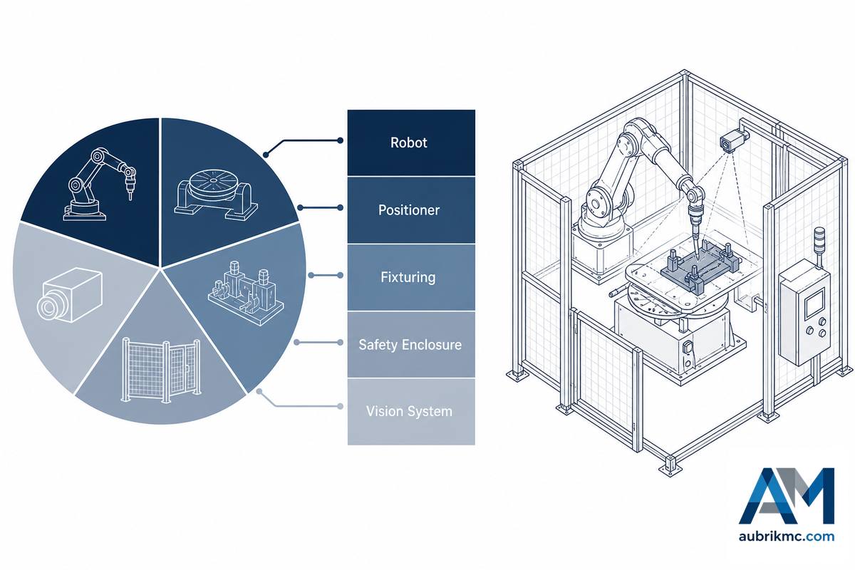
Full robotic welding cells ranges from roughly $50,000 (entry cobot tier) to $600,000+ (multi-robot custom configurations). Five factors are used to move a quote into a higher or lower tier: positioner payload class, axes, vision/sensing method, enclosure type, level of customization. Have each vendor break out each factor instead of a single lump sum quote – this is the only way to compare cobot quotes objectively. A Cal Poly engineering case study on fixture design for robotic welding found the fixture itself, not the robot, was the deciding factor in whether the economics worked out at all.
Fixture-First Diagnostic Worksheet — 5 Setup Mistakes That Delay ROI
- Bypassing Tool Center Point (TCP) calibration – when you use an uncalibrated reference, even on straight welds, you’ll get random results when welding to a circle, at an angle or a multi-pass.
- The fixture is easily over-constrained – it will bind against the workpiece with even slight thermal expansion, and the weld sequence will actually fight against the material’s own shape when heated.
- Failure to maintain the consumables will lead to debris buildup in the wire liner, the single largest cause of feed issues-changes to liner and guide components should be considered scheduled maintenance, not an on-demand fix.
- For both directions, incorrect power source selection hurts-undervolting for thicker parts makes the machine constantly search for proper arc settings, whereas over-volting is wasteful in terms of money.
- Choosing not to program with the offline software necessitates manually programming every single job directly on the robot-which can consume anywhere from 20% to 30% of a shift on high-mix applications-while offline allows the designer to build and test tool paths offline without impacting cell availability.
Beyond the machine price tag itself, also budget for fixturing (the cost of which varies with complexity, but can be comparable to the price of the machine in very complex applications-$5,000-$40,000+), shipping and installation ($5,000-$15,000), operator training ($3,000-$10,000), and an annual service contract ($5,000-$25,000). Fixturing is the cost first-time buyers most often miss, a single complex fixturing station can run as much as $5,000 on its own, on top of the cell price.
Safety, Standards & Compliance, The 2025 Compliance Fork
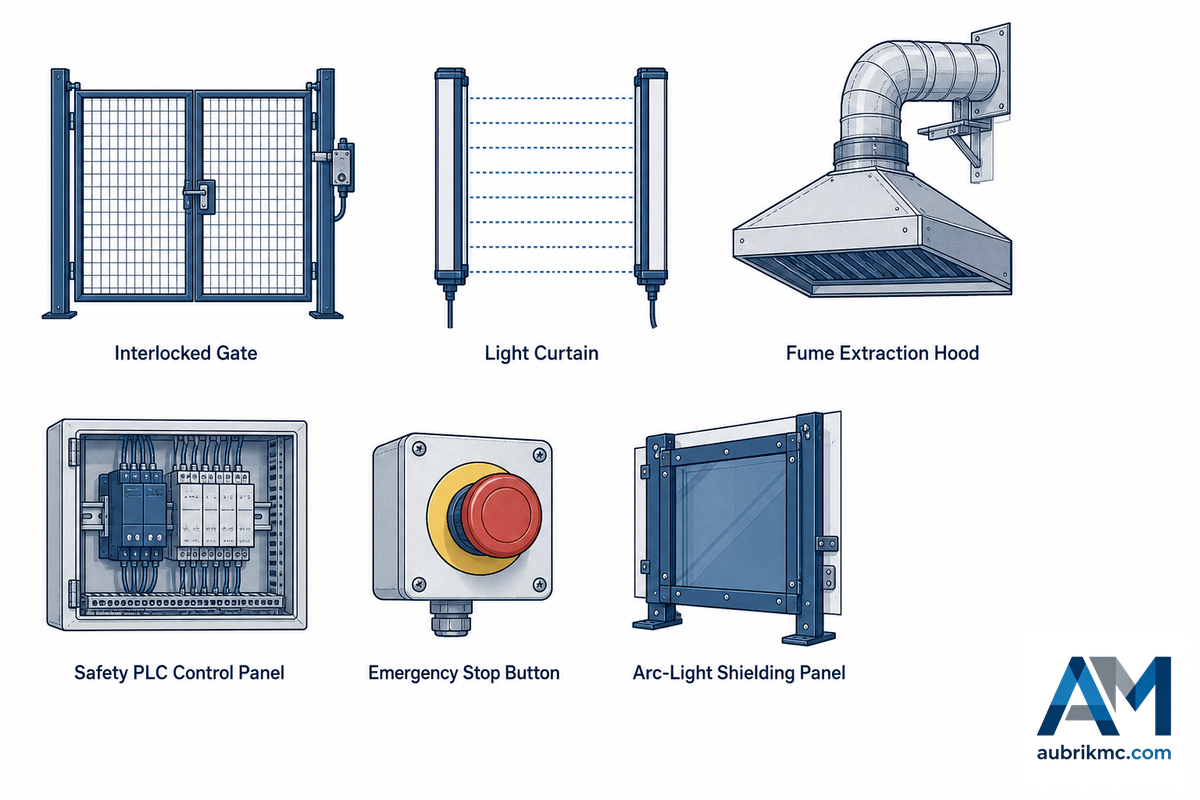
Robotic welding cell units sold and/or installed from the latter part of 2025 onward will be at the forefront of a significant safety-compliance fork: In 2025, the standards that have provided guidance for US industrial robot safety since 2012 underwent substantial revision, even including the renaming of the standards-issuing body.
| Standard | Scope |
|---|---|
| ANSI/A3 R15.06-2025 | U.S. national adoption of ISO 10218 Parts 1–2; revises the 2012 edition published under the standard’s former name, ANSI/RIA R15.06 |
| ISO 10218-1/2:2025 | International robot and robot-system safety requirements; third edition, effective 2025 |
| ISO/TS 15066 | Collaborative robot force/speed limiting — applies to cobot cells specifically |
| AWS Z49.1 | General safety in welding, cutting, and allied processes |
| AWS D16.1M/D16.1 | Safety practices specific to robotic arc welding — a distinct layer from general robot safety standards |
For any buyer, the practical upshot is limited but significant: you need to ascertain, for any machine you’re considering, what edition of the R15.06 safety standard that cell was designed against. While a machine designed against the older 2012 version isn’t automatically out of compliance, if you’re purchasing in 2026 you’ll want a machine designed against the newer 2025 version-and you may be surprised at how few current marketing materials reflect that.
It’s not only about physical guards, however. A 2025 article in Scientific Reports concerning welding-robot operator reliability, which applies human-reliability assessment (HRA) methods-TESEO and HEART-to the human aspect of system operation, highlights the role of HMI quality, workload, task documentation clarity, and task complexity as significant factors in risk of incident.
⚠️ Important
The real world isn’t an abstract consideration: OSHA incident records include the case of a worker getting his cart caught on the elevated enclosure as he attempted to position it into the work area of a robotic welding cell. Welding fume extraction is a related, often-overlooked compliance item — an enclosed cell concentrates fumes that a manual bay would otherwise vent naturally, so extraction capacity has to scale with the enclosure, not just the process.
What Changed in the 2025 Robot Safety Standard Revision?
See Answer
ANSI/A3 R15.06-2025 is the United States national adoption of ISO 10218-1:2025 and ISO 10218-2:2025 and it supersedes the ANSI/RIA R15.06:2012.
Independent trade-press coverage indicates this is a substantive overhaul rather than a simple rename, meaning a machine designed against the 2012 standard will not automatically meet the 2025 requirements. Buyers evaluating a cell in 2026 should ask the vendor which edition their safety documentation references before assuming compliance.
Offline Programming, Vision & Keeping the Cell Running
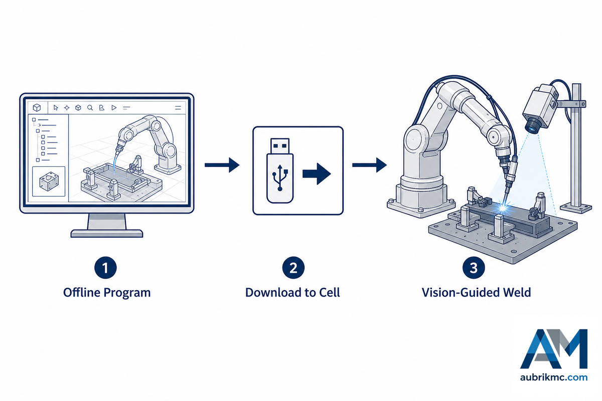
Instead of programming on the actual robot, tying up the equipment at a shift change, an engineer can offline program (OLP) a weld path on their desktop and download it to the cell at a shift change. That offline-programming approach continues to be a vibrant and actively developed engineering technology, shown by a recent U.S. patent (US12277369B2) for simulating weld paths directly from 3D scans of a real part. High-mix job shops and structural-steel fabricators — where a new part can hit the floor every shift — get the most practical benefit from offline programming, since teach-pendant programming a fresh path on the robot itself is exactly the cell downtime that offline programming is meant to eliminate. Modern offline software is easy-to-use enough that a technician can build and check the weld path in 3D visualization, set the end points for each pass, and confirm there’s no collision before ever touching the real robot.
Vision and seam-tracking sensors close the gap between the taught path and a physical part that differs slightly from the CAD model; often, a laser or structured-light sensor determines the real location of the joint and makes instantaneous adjustments to the torch path, the mechanism behind integrated seam-tracking holding the weld quality level even when there are significant joint fit-up deviations. For high-mix welding tasks in particular, this is what keeps quality consistent without a full re-teach for every part variation.
💡 Pro Tip
OSHA’s technical manual itself points out that, “robot controller programming is not standardized by the robotics industry, and vendors commonly have their own programming languages or methods that require special worker training.” Remember to build the cost of vendor-specific programming training into your budget as a legitimate operating expense.
Industry Outlook, What’s Changing in 2026
The 2026 purchasing picture is being colored by two concrete drivers that transcend market size; both are driver-level issues: The industry-wide shortage of skilled workers is driving more companies, large and small, toward automation as an ongoing solution for workforce continuity as opposed to solely a cost consideration; cobot cells specifically exist to free up experienced welders for higher-value work, a productivity lever that lets one person manage or program multiple work cells rather than individually manage each joint manually. Matching automation needs to actual welder availability, not just budget, is increasingly the honest starting point for a 2026 purchase decision. ANSI/A3 R15.06-2025’s revision means that when purchasing cells for deployment in 2026, buyers need to evaluate solutions against the most current version of the safety standard rather than rely on the older 2012 version referenced in many vendor brochures and specification sheets; it represents a fundamental shift in the criteria that constitutes the correct buying decision this year. Skip this check and the risk isn’t abstract: a cell specified and certified against the outgoing 2012 edition can force an expensive re-certification or retrofit once an auditor or insurer flags the mismatch, a cost that lands entirely on the buyer, not the vendor who sold against the older standard.
There’s variability among market-research firms regarding estimates for the robotic welding market size, but forecasts around the $7 billion to $11 billion range for 2025 with continued growth into the early 2030s appear across multiple market-research sources. These numbers are intended as broad context, and the industry and labor-market trends cited above should carry more weight for purchasing decisions made in 2026 than any specific projected growth rate.
For your 2026 automation project: Determine your part’s production-volume profile (see Section 7 above) first. Next, ensure your intended vendor is referencing the most current safety-standard edition (2025) on their specification sheets (see Section 8), and then you can move on to evaluating cost quotations with the framework outlined in Section 7.
Frequently Asked Questions
Q: Why choose a robotic welding cell over manual welding?
Expand Answer
The primary reason is the amount of arc-on time, not simply the maximum raw weld speed. Human operators generally run the arc 15-40% of a shift; a robotic cell can push that to 50-85% since the system does not take breaks between parts, fatigue out, or have the need to wind down at the end of a shift. Since the labor represents the vast majority of the cost of any given weld, reclaiming that unused time is often the single largest lever in the automation business case -although, as noted, this does not guarantee the sale for every production profile.
Q: How long does it typically take to install and commission a robotic welding cell?
View Response
Installation time typically takes 3-5 days for a pre-engineered cell and an additional 1-2 weeks for programming and operator training. Custom or heavily configured positioner cell solutions commonly range from 4-8 weeks end-to-end. Cobot cells generally fall on the shorter side of this range due to their user-friendly programming interfaces.
Q: Can a robotic welding cell be reprogrammed for different parts?
Show Response
Yes, this is where a cell fundamentally differs from a single-purpose, fixed automation line. Reprogramming may be achieved via teach pendant commands, offline programming software, or in the case of cobots, through hand guidance and a 3D CAD model import for automated path generation, negating the need for complete manual re-teach.
Q: Does a robotic welding cell need a dedicated operator?
See Details
Not full-time. Typically, one technician handles the programming and ongoing quality monitoring of a cell while another individual handles part loading and unloading part-time, potentially across multiple cells.
Q: What’s the difference between a cobot welding cell and a traditional robotic welding cell?
Expand Details
A cobot welding cell uses a collaborative robot designed for operation under ISO 10218-2 and ISO/TS 15066 force and speed limitations with little to no perimeter fencing. This makes it ideal for high-mix, low-volume, frequent changeover applications where a small footprint is desired. Traditional cells use a full-speed industrial robot that requires complete guarding (light curtains, interlocked doors, etc.) and is geared for serial production where maximum raw output is paramount. Cost reflects these differences, with cobot cells often falling into the $50,000-$150,000, category, whereas pre-engineered single-station cells fall into the $130,000-$250,000 category. Neither technology is inherently superior; the decision depends on your part mix and volume.
Q: Is a robotic welding cell worth it for a small or medium-sized shop?
View Explanation
Frequently, especially with cobots, provided you have dozens of repeat parts running per day. It is important to do your own math on your arc-on-time and labor costs versus the price quoted; production profile matters far more than shop size.
Why We Write This
Aubrik has been designing and manufacturing welding automation equipment (positioners, manipulators, robotic welding systems) since 1999, and this guide incorporates insights derived from our manufacturing expertise along with independently verified industry, academic, and governmental resources. We’ve noted instances where a data point couldn’t be independently corroborated, rather than present it as exact. Reviewed by the Aubrik technical team.
References & Sources
- Robotics, OverviewOccupational Safety and Health Administration
- OSHA Technical Manual, Section IV: Chapter 4, Robotic Arc Welding SafetyU.S. Department of Labor
- ISO 10218-2:2025, Robotics, Safety RequirementsInternational Organization for Standardization
- Updated ANSI/A3 Standards Address Industrial Robot SafetyThe Robot Report
- Choosing the Right Robotic Weld Cell for Your OperationThe Fabricator
- Checklists for Robotic Welding SuccessThe Fabricator
- Comparative Study of Robotic and Manual Welding in a Low Volume-High Mix Manufacturing Environment (JR Test 3)Minnesota State University, Mankato
- Comparative Study of Robotic and Manual Welding in a Low Volume-High Mix Manufacturing Environment (JR Test 2)Minnesota State University, Mankato
- Welding Robot Operator Reliability Analysis Using Extended TESEO and HEART MethodsScientific Reports (Nature)
- US12277369B2, Generating Simulated Weld Paths for a Welding RobotUSPTO / Google Patents
- AWS/ANSI Z49.1, Safety in Welding, Cutting, and Allied ProcessesAmerican Welding Society
- AWS D16.1M/D16.1, Specification for Robotic Arc Welding SafetyAmerican Welding Society
- Thirteenth International Conference on Computerization of WeldingGovInfo / U.S. Government Publishing Office
- Module 2, Welding and Cutting ProcessesU.S. Nuclear Regulatory Commission
- Design and Implementation of a Fixture for Robotic WeldingCalifornia Polytechnic State University
- ISO 10218-2:2025, Robotics, Safety Requirements, Part 2International Organization for Standardization