Get in Touch with Aubrik Company

How to Size and Specify a TIG Turntable and Rotary Welding Positioner for Precision Circular Welds

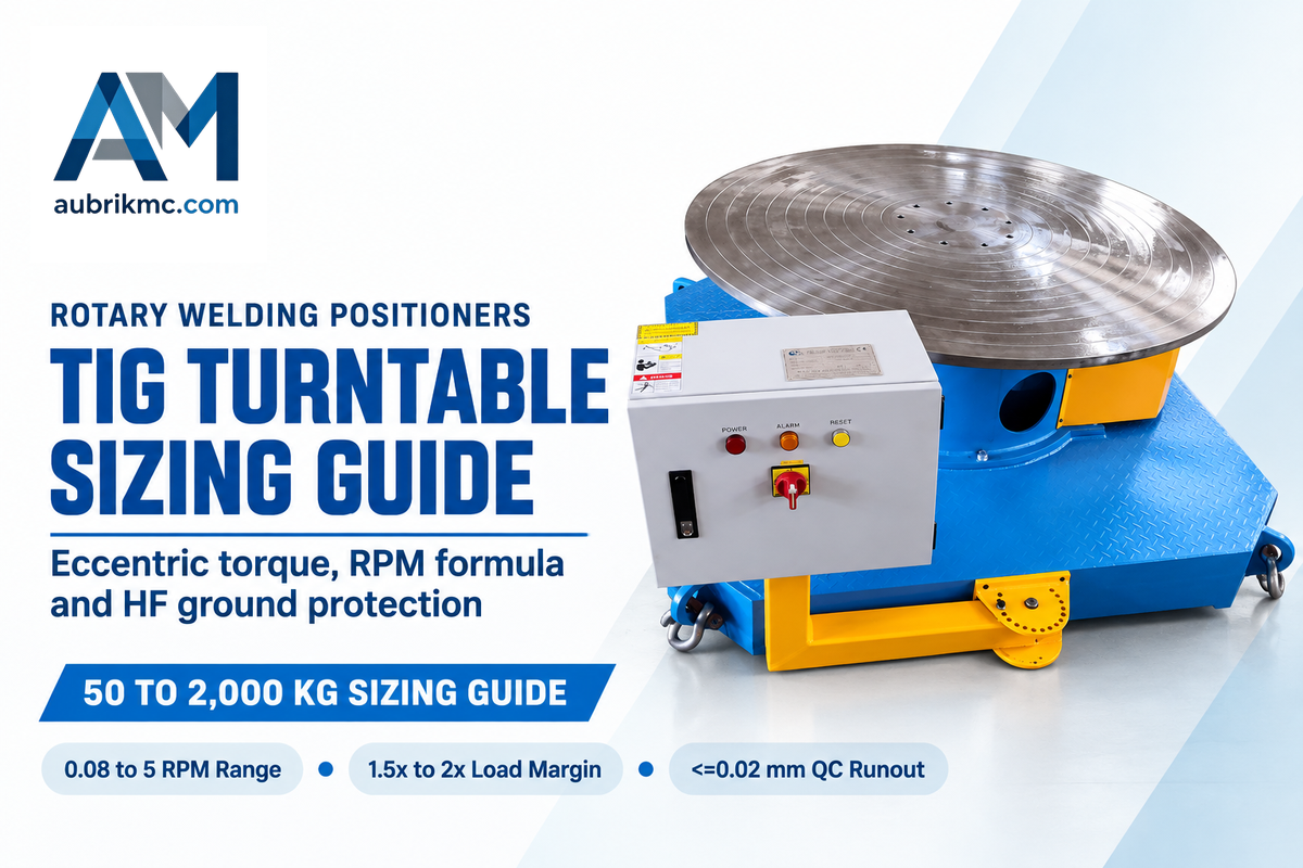
A TIG turntable is a motorized rotary welding positioner that rotates pipes and flanges beneath the torch. The listed Aubrik BY models cover a range of 0.08 to 5 RPM and have differing speed limits. When selecting a welding turntable, a 1.5x to 2x payload margin for offset fixtures and accurate gravitational torque calculations are required. Buyers must also specify closed-loop low-speed regulation and HF ground isolation.
What a TIG Turntable Weld Positioner Does in Precision Fabrication
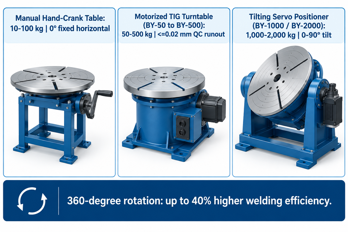
A dedicated TIG turntable (or weld positioner) rotates a circular workpiece around a central spindle. This motion lets the welder hold a steady torch angle in the flat (1G) or horizontal-fillet (2F) position. According to industrial welding turntable production data from Aubrik, circular seams consume 30% to 50% of shop clock time. Motorized 360-degree rotation raises welding efficiency by up to 40%.
Vocational and automated GTAW pipe welding and robotic positioner curricula make use of constant surface speed to ensure even heat input on thin walled stainless steel and titanium. Stable welding current and arc voltage are necessary for a stable arc. Controlled current downslope and filler addition aid crater filling at the end of the weld. Case studies in The Fabricator show that positioning downhand helps reduce crane handling time and improves consistency and weld quality.
What Is a Welding Turntable and How Is It Utilized in TIG Fabrication?
A welding turntable is a single axis or tiltable rotary table that clamps round parts in a 3-jaw chuck or T-slot faceplate. It supports circumferential Gas Tungsten Arc Welding (GTAW) in industry. To use it, the operator sets the rotation speed in RPM, strikes an arc, and presses a foot switch. The component then turns smoothly beneath a welding torch. Of particular interest is how smoothly rotation speed is translated through thin exhaust tubes and fittings. Workpiece runout, torch clearance, and current control all affect tungsten contact and localized heat-input spikes. Rotating the workpiece beneath the torch lets the welder maintain a steady torch angle across batch runs.
| Equipment Type | Payload Envelope | Speed Control & Repeatability | Tilt Range | Shop Application & Cost Baseline |
|---|---|---|---|---|
| Manual Hand-Crank / Bearing Table | 10–100 kg | Manual indexing by hand | 0° fixed horizontal | Low-volume tacking and layout only |
| Motorized Horizontal TIG Turntable (BY-50 to BY-500) | 50–500 kg | 0.5–5 RPM (BY-50) and 0.3–4 RPM (BY-100) stepless AC drive; ≤0.02 mm QC runout | 0° fixed horizontal | Fixed-horizontal comparison baseline; continuous circumferential seams |
| Tilting Servo Rotary Welding Positioner (BY-1000 / BY-2000) | 1,000–2,000 kg (5,000 kg custom) | 0.1–2 RPM (BY-1000) and 0.08–1.5 RPM (BY-2000) DC servo drive | 0–90° motorized (135° custom) | Heavy offset pipe spools, downhand fillet welding, and robotic cells |
TIG Turntable Load Capacity, Eccentric Torque, and Tilt Sizing
Loading capacity nameplates on rotary welding positioner and turntable apply only if the center of gravity (CG) sits on the spindle axis. Once a manifold mounts off center or tilts from horizontal toward vertical, gravity creates a rotational torque and a bending moment that contribute to tilting. The University of Guelph rotational torque tutorial and Koike Aronson sizing guide separate the two types of load vectors.
Start by determining gross loading by summing the masses of the workpiece, 3-jaw chuck, and any custom fixture or counterweights. US distributor guides on WeldingMart suggest a 1.5X-2X safety margin on offset jigs. Engineers set the torque design margin separately. Next, assess rotational torque and tilt torque for all axes.
- The maximum gravitational torque acts at a distance eradial from the spindle and is along the faceplate, which is tilted by θ with respect to the horizontal. Here eradial is the radial distance of center of gravity from the spindle and W is the weight of the part.
- Gravitational tilt torque is equal to weldment weight multiplied by the signed horizontal lever arm from the tilt axis to the center of gravity. As the workpiece tilts and rotates, axial overhang and radial eccentricity both affect this lever arm.
Consider a worked example for a combined 85 kg 316L stainless pipe-and-fixture assembly with a 120 mm (0.12 m) radial CG offset. Gravitational force equals 85 kg × 9.81 m/s² = 833.85 N. With a horizontal spindle, 833.85 N acting at a radial eccentricity of 0.12 m produces a peak gravitational torque of 100.1 N·m about the spindle. Applying a separately selected torque safety factor of 1.25× gives 125.1 N·m, and drive sizing also includes friction and acceleration torque. With a vertical spindle, gravity produces no torque about that axis. Distinguish the payload-capacity margin from the torque-design margin. For this eccentric assembly, apply the 1.5× to 2× payload margin and check the manufacturer’s eccentric load chart. Rolled 1G pipe welding uses a horizontal pipe axis and rotation to keep the weld at the top. Among the Aubrik models listed here, BY-1000 and BY-2000 provide motorized faceplate tilt (up to 500 N·m gear torque) to orient a spindle-mounted pipe horizontally. Review pipe welding turntable torque and chuck bore sizing and welding positioner overload signs and root causes when checking offset loads.
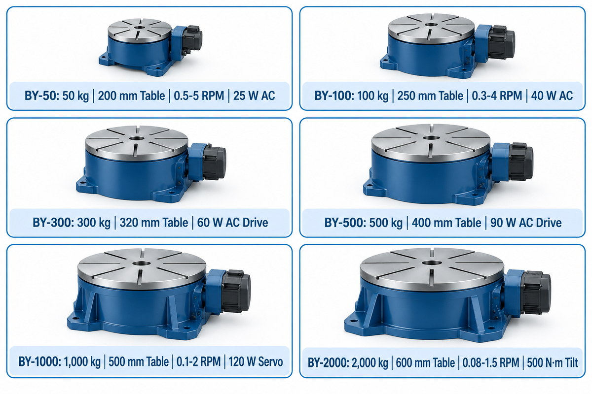
| Model | Rated Load Capacity | Table Diameter | Rotation Speed Range | Drive Motor Power | Tilt Angle & Drive Class |
|---|---|---|---|---|---|
| BY-50 | 50 kg | 200 mm | 0.5–5 RPM | 25 W | 0° fixed horizontal; AC stepless regulation |
| BY-100 | 100 kg | 250 mm | 0.3–4 RPM | 40 W | 0° fixed horizontal; AC stepless regulation |
| BY-300 | 300 kg | 320 mm | Confirm against model-specific datasheet (series spans 0.08–5 RPM) | 60 W | 0° fixed horizontal; AC stepless regulation |
| BY-500 | 500 kg | 400 mm | Confirm against model-specific datasheet (series spans 0.08–5 RPM) | 90 W | 0° fixed horizontal; AC stepless regulation |
| BY-1000 | 1,000 kg | 500 mm | 0.1–2 RPM | 120 W | 0–90° motorized tilt; DC servo drive |
| BY-2000 | 2,000 kg (5,000 kg custom) | 600 mm | 0.08–1.5 RPM | 180 W | 0–90° / 135° motorized tilt; DC servo drive (500 N·m gear torque) |
Welding Turntable Speed Control, RPM Formula, and Motor Drive Selection
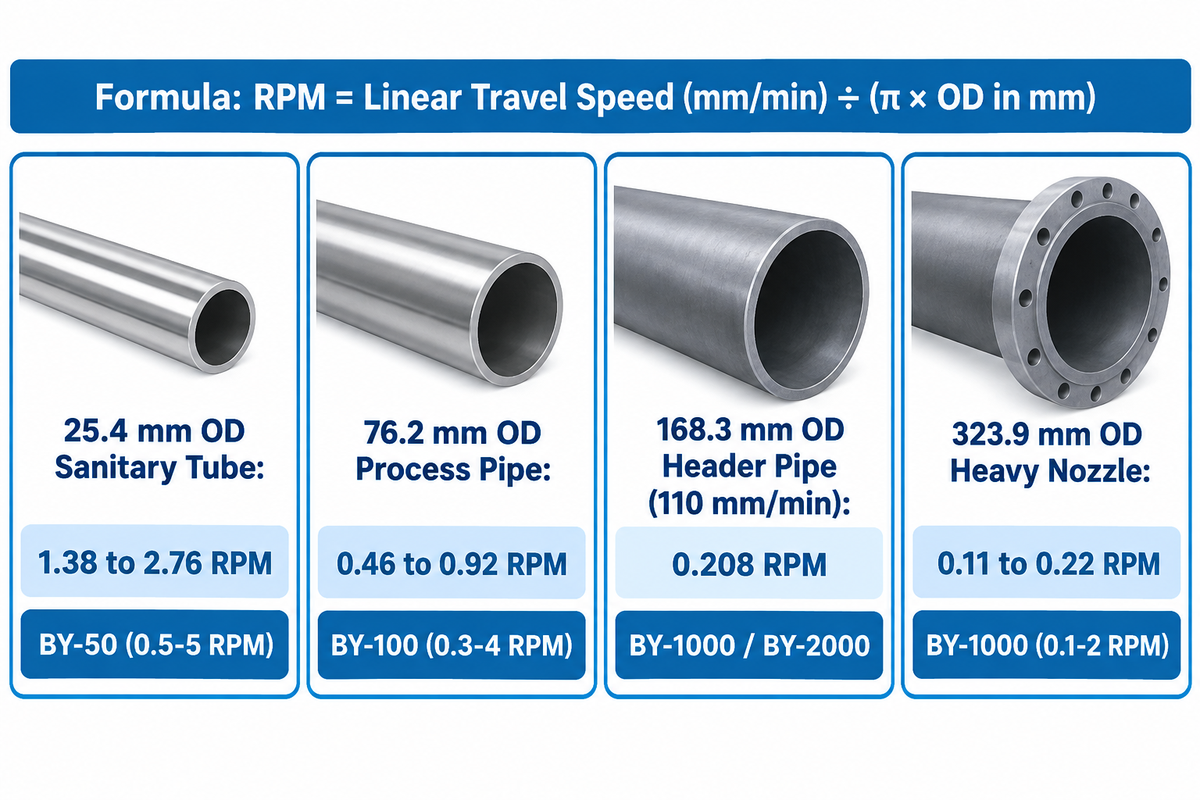
Choosing the speed range and speed control architecture of a variable speed turntable reduces low-speed fluctuations on large pipes and ensures sufficient top RPM on small fittings. Engineers convert linear tig welding travel speed into spindle rotation speed using standard circumferential kinematics: RPM equals linear travel speed (mm/min) divided by workpiece circumference (π × outer diameter in mm).
Consider a 6-inch Schedule 10S stainless pipe (168.3 mm OD, circumference 528.7 mm) welded at 110 mm/min linear travel speed. The required spindle speed is 110 ÷ 528.7 = 0.208 RPM. Using a 1,520 mm OD vessel ring, its circumference is approximately 4,775.2 mm (188.0 in). That ring requires approximately 0.0628 RPM at 300 mm/min per Koike Aronson’s RPM calculation. Conversely, small tubing from 25 mm to 150 mm OD welded at 75 to 350 mm/min requires 0.16 to 4.46 RPM. State-approved training lists like the California BPPE welding fabrication report pair GTAW pipe stations with motorized positioners across these diameters.
Operators adjust speed (or make a fine panel adjustment) on the controller to match pipe diameter. For low output speeds, open-loop brushed DC drives can slow down under load or rotate unevenly when available torque cannot overcome friction and cogging. This behavior is affected by gear reduction and controller performance. Suitable gear reduction and closed-loop speed control help maintain smooth low-speed rotation under changing loads. Under changing loads, speed control can maintain steady rotation at low speeds. Dynamic braking can be used to dissipate energy during deceleration. For smooth manual and semi-automatic operation, Aubrik uses stepless AC geared-drives on BY-50 through BY-500. For the BY-1000 and BY-2000, Aubrik uses precise DC servo drives. The positioning system’s accuracy varies with load and is affected by feedback resolution, drivetrain backlash, and structural stiffness. A given angular error causes a greater linear displacement farther away from the spindle axis.
| Pipe Category & Workpiece Outer Diameter (OD) | Circumference (π × OD) | RPM at 110 mm/min (Root Pass GTAW) | RPM at 150 mm/min (Standard Fill Pass) | RPM at 220 mm/min (Fast Cap / Pulsed TIG) | Matching Aubrik Model Tier (Continuous Range) |
|---|---|---|---|---|---|
| Small Sanitary Tube — 25.4 mm OD | 79.8 mm | 1.38 RPM | 1.88 RPM | 2.76 RPM | BY-50 (0.5–5 RPM covers all three speeds) |
| Thin Exhaust Tube — 38.1 mm OD | 119.7 mm | 0.92 RPM | 1.25 RPM | 1.84 RPM | BY-50 (0.5–5 RPM covers all three speeds) |
| Dairy Process Line — 50.8 mm OD | 159.6 mm | 0.69 RPM | 0.94 RPM | 1.38 RPM | BY-50 (0.5–5 RPM) or BY-100 (0.3–4 RPM) |
| Sanitary Header Tube — 63.5 mm OD | 199.5 mm | 0.55 RPM | 0.75 RPM | 1.10 RPM | BY-50 (0.5–5 RPM) or BY-100 (0.3–4 RPM) |
| Schedule Process Pipe — 76.2 mm OD | 239.4 mm | 0.46 RPM | 0.63 RPM | 0.92 RPM | BY-100 (0.3–4 RPM covers all three speeds) |
| Medium Utility Pipe — 101.6 mm OD | 319.2 mm | 0.34 RPM | 0.47 RPM | 0.69 RPM | BY-100 (0.3–4 RPM covers all three speeds) |
| Standard Spool Pipe — 114.3 mm OD | 359.1 mm | 0.31 RPM | 0.42 RPM | 0.61 RPM | BY-100 (0.3–4 RPM covers all three speeds) |
| Chemical Header Pipe — 168.3 mm OD | 528.7 mm | 0.21 RPM | 0.28 RPM | 0.42 RPM | BY-1000 (0.1–2 RPM) or BY-2000 (0.08–1.5 RPM) |
| Heavy Vessel Nozzle — 323.9 mm OD | 1,017.6 mm | 0.11 RPM | 0.15 RPM | 0.22 RPM | BY-1000 (0.1–2 RPM) or BY-2000 (0.08–1.5 RPM) |
Preventing TIG High-Frequency Interference and Rotary Ground Damage
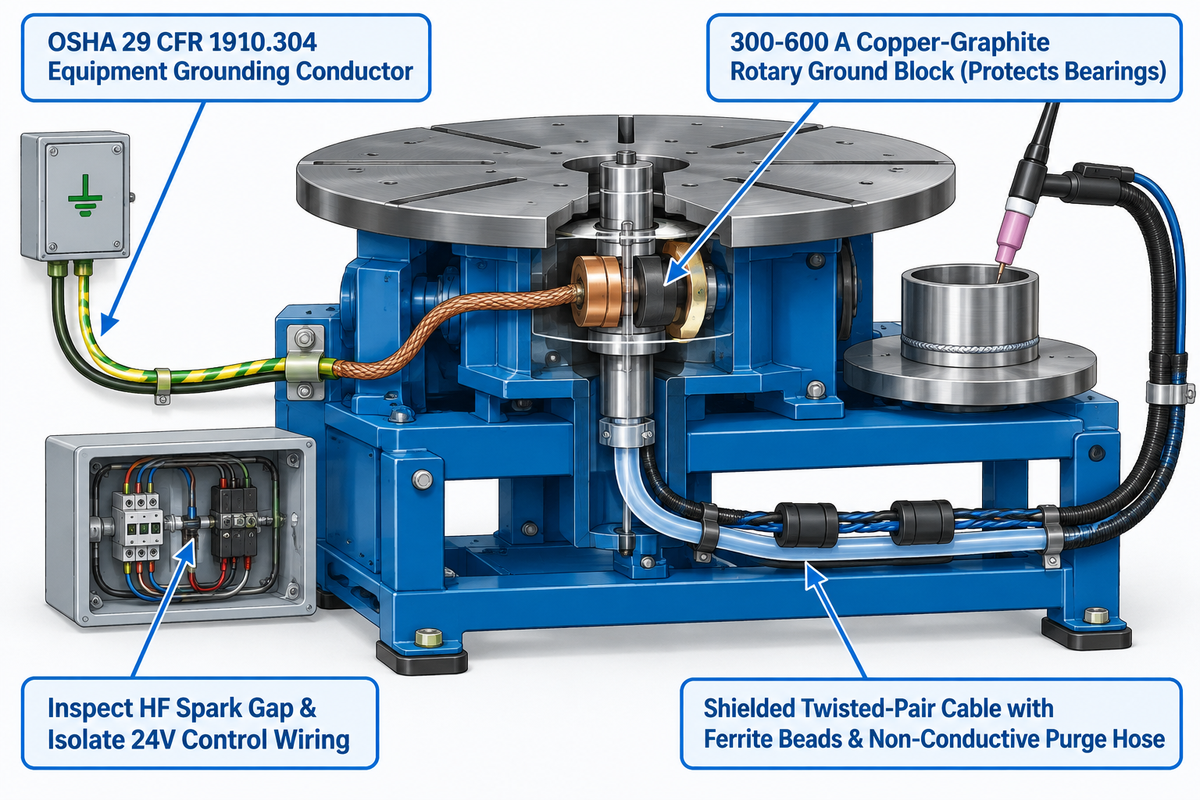
High-frequency (HF) arc starting in GTAW produces high-voltage radio-frequency bursts that couple into unshielded motor speed boards, encoders and foot-switch cables. While 100 A to 350 A welding return current crossing ball bearings causes micro-arcing that results in pitting and ruins mechanical smoothness. This pitting also degrades how a slewing bearing handles axial and tilting moments.
Why Is My TIG Turntable Not Working or Running Erratically During Arc Start?
A TIG turntable stalls, resets its display or behaves erratically during arc start when high-frequency electromagnetic interference (EMI) enters an unshielded PWM controller. Erratic motion also occurs when welding return current arcs across the main shaft bearings. Technical bulletins from Bancroft Engineering confirm that GTAW high-frequency stabilization causes severe radio-frequency interference in solid-state positioner drives. To prevent failure of the board, a low-impedance ground path and isolated control circuits must be implemented. Technical bulletins from Bancroft Engineering confirm this.
The following four measures help protect the operator and the machine’s electronics.
4-Point HF Grounding & Purge-Bore Matrix
- Per OSHA 29 CFR 1910.304(g)(5) and (g)(8)(i), fixed metal frames require a permanent, continuous equipment grounding conductor. Run this conductor with the power supply circuit conductors; a standalone earth rod never replaces this fault path.
- Clamp the welding power source work lead to the spring-loaded copper-graphite rotary ground block (300-600 A) located on the turntable. A dedicated rotary brush, in good electrical contact, will provide a low resistance return path and reduce arcing across the bearings.
- The welder’s high frequency (HF) spark gap must be inspected and the 24V control wiring isolated from the torch leads as part of Bancroft Engineering’s RFI protection protocol. Additional grounding as required by the manufacturer’s wiring diagrams may also be implemented.
- Shielded twisted-pair cable with ferrite beads should be used to convey signals from the foot pedal and/or robot handshake. Non-conductive gas hose fittings should be used through the hollow spindle bore to ensure the purge line never carries stray current.
3-Jaw Welding Chucks, Radial Runout Limits, and Hollow Spindle Purging
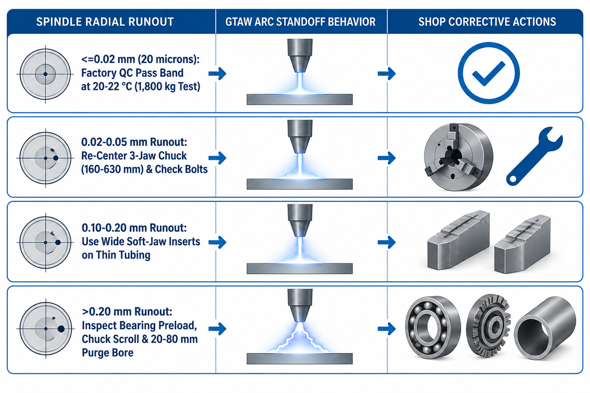
In manual and mechanized GTAW, tungsten-to-workpiece arc length sits between 1.0 mm and 2.0 mm. Faceplate wobble or chuck eccentricity alters torch standoff during rotation. The supplied research reports radial runout of ≤0.02 mm (20 microns) at 20–22 °C during a 24-hour stress test with a 1,800 kg load. That qualification across 14 gear-drive configurations locked in the hardened alloy steel gear pair for long-term durability.
Engineers should distinguish two machine accuracy metrics—pose repeatability and spindle radial runout—from application-specific weld fit-up requirements. In robotics literature, ISO 9283:1998 manipulator performance testing (and 14-criteria robot pose repeatability studies) describes test methods for manipulator pose repeatability. Rotational accuracy at the weld joint also reflects measurement radius and chuck clamping. Once a thin tube is clamped in a 3-jaw chuck, excessive jaw pressure can ovalize thin-wall tubing. Vendors specify low-speed stability qualitatively as smooth stepless rotation rather than a numerical RPM-percentage tolerance. Carbon-steel assemblies under AWS D1.1/D1.1M:2025 Structural Welding Code—Steel (and its 2025 edition updates) follow structural joint tolerances. Meanwhile, rotary GTAW studies in MDPI Materials and PubMed multi-pass GTAW research show that gravitational orientation and standoff variation alter bead geometry.
Which Rotary Welding Turntables Come with Three-Jaw Self-Centering Chucks?
Industrial welding turntable packages from Aubrik (BY-50 through BY-2000), MK Products (CobraTurn with optional 005-0812 chuck), and Arc-Zone / PROFAX pair with quick-action 3-jaw self-centering welding chucks. These chucks bolt onto the faceplate with a machined adapter plate and span 160 mm to 630 mm clamping diameter. Reversible jaws allow for greater torch clearance. Aubrik offers configurable 20 mm to 80 mm hollow purge spindles and HF-shielded control cabinets for the BY-Series. Customers are encouraged to ask for model-specific eccentric load charts during an RFQ.
When welding austenitic stainless (304L/316L), duplex alloys, or titanium pipes, a 20 mm to 80 mm hollow spindle through-bore routes an internal purge hose through the rotation axis. This through-bore reduces hose wrapping as you rotate the workpiece. Patent publication CN103600196A on welding positioner control systems is an invention patent application publication describing a welding positioner control system with coordinated rotary platform speed regulation. Clean root welds also require local purge dams, a sintered diffuser to stop turbulence, and a sized vent port to prevent over-pressurization. Pair these fittings with argon arc surfacing shielding gas checks.
| Radial Runout Band | Arc Standoff Behavior | Weld Pool & Bead Geometry Factors | Recommended Shop Action |
|---|---|---|---|
| ≤0.02 mm (20 microns) | Limits spindle-related arc-gap variation | Root penetration and crown width also reflect loaded workpiece runout and welding parameters | Aubrik reports this factory runout pass band across BY-50 to BY-2000 at 20–22 °C |
| 0.02–0.05 mm | Minor periodic standoff variation on fixed-torch setups | Bead appearance reflects travel speed, current stability, and joint fit-up | Re-center 3-jaw chuck jaws and check faceplate mounting bolts |
| 0.10–0.20 mm | Periodic standoff variation with a fixed torch; >1.5 mm drift requires additional displacement | Penetration and bead shape also reflect welding parameters and joint fit-up | Wide soft-jaw inserts distribute clamping force on thin tubing |
| >0.20 mm | Noticeable electrode-to-workpiece gap variation during rotation | Increased risk of uneven fusion or electrode contact when torch height is fixed | Inspect spindle bearing preload, chuck scroll wear, and fixture concentricity |
Foot Pedals, Torch Holders, and Robotic Cell Fieldbus Integration
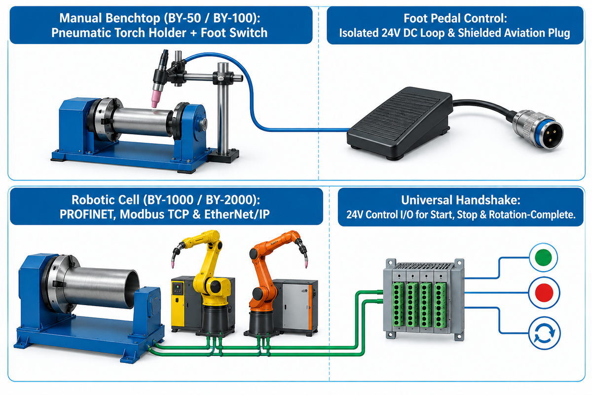
Pair a motorized turn table operator control to shop batch volume: use foot pedals for manual tasks and controller handshakes for automated and cobot cells. For manual benchtop work on automotive exhaust collectors, vehicle slip-joint adapters and aerospace brackets, use a compact BY-50 or BY-100 with an adjustable pneumatic torch holder. This configuration provides good reliability.
Can You Use a Foot Pedal with a Rotary Welding Table?
Rotary welding positioners with a compatible switching input allow the use of a start/stop foot pedal, such as the standard Aubrik foot switch or MK Products 005-0747. Models with a compatible variable-speed input allow the use of a heavy duty potentiometer speed-control pedal, such as MK Products 005-0746. It enables the welder to adjust RPM dynamically mid-weld. For HF TIG work, verify the pedal employs an isolated 24V DC control loop and a shielded aviation plug.
In automated and cobot cells, protocol mismatches at commissioning can delay integration with FANUC R-2000iC, FANUC CRX cobots, or KUKA KR CYBERTECH controllers. Peer-reviewed industrial robot calibration and positioning literature shows that synchronized multi-axis motion requires deterministic controller communication. Aubrik loads PROFINET, Modbus TCP, and EtherNet/IP stacks natively onto the BY-1000 and BY-2000 controllers. All six BY models also provide 24V control I/O for simple start, stop, and rotation-complete triggers.
TIG Turntable vs. Turning Rolls vs. Orbital Weld Heads
Fixed-horizontal welding turntable models cover most flange and short spool fabrication at roughly 60% of the capital cost of a two-axis tilting positioner. Long or heavy assemblies can use a suitably rated positioner with auxiliary supports. Pipe rotator turning rolls support and rotate cylindrical workpieces, and an orbital head on a closed chamber moves the torch around a workpiece that fits through it.
A cantilevered faceplate exceeds its rated bending capacity when the combined workpiece-and-fixture weight force multiplied by its perpendicular lever arm exceeds the rated bending moment. Assess overhang moment and additional support requirements before loading long spools. Use a suitable tailstock or turning rolls when the unsupported assembly exceeds the positioner’s rated limits. When vessel mass climbs into the 5-ton to 1,000-ton range (as documented in The Fabricator), roller beds support the cylinder without spindle overload. Buyers can cross-check borderline parts using Aubrik’s rotator vs. positioner selector tool.
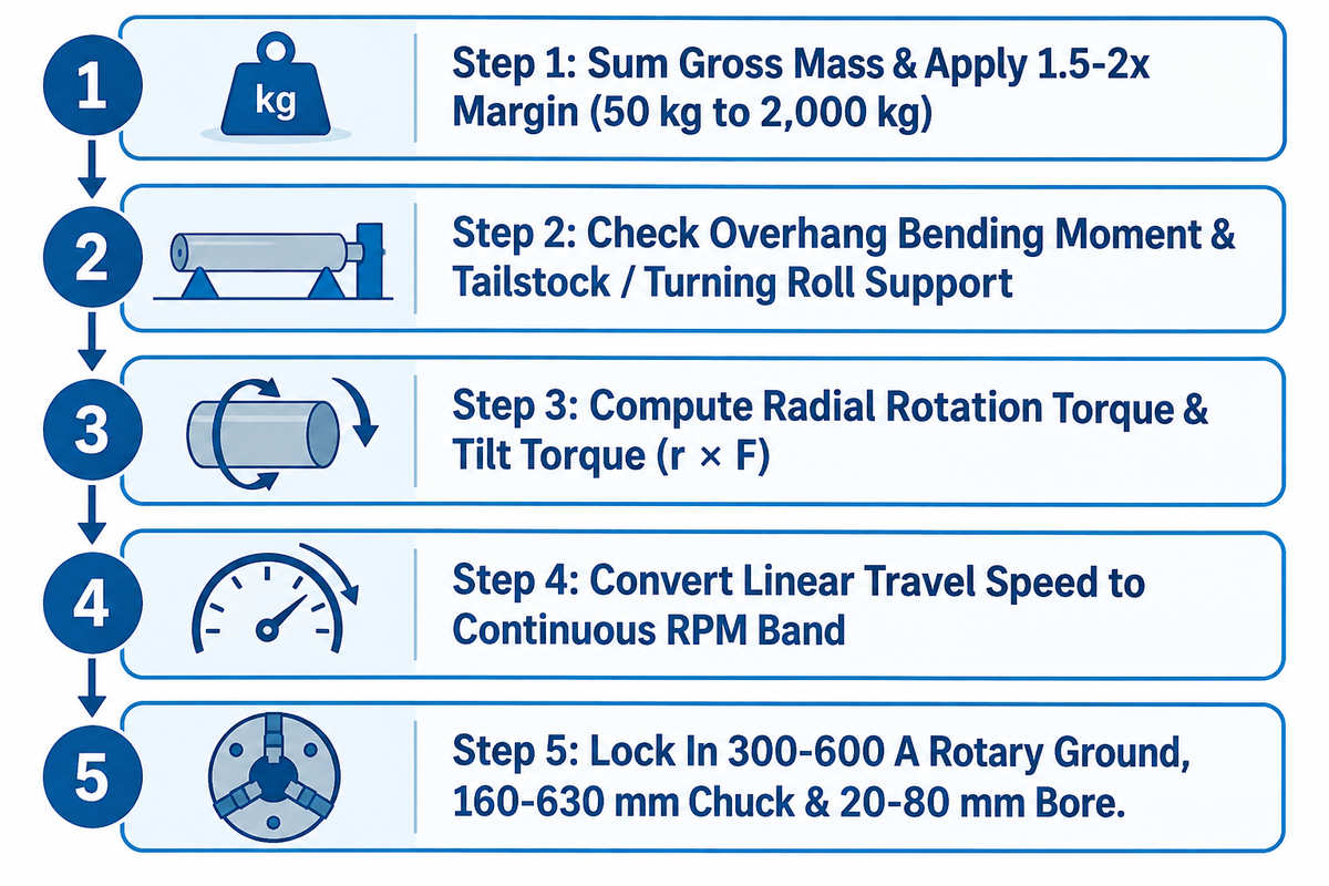
5-Step TIG Turntable RPM-to-Torque Sizer
- Step 1 – Sum Gross Mass & Apply 1.5-2x Margin: Add workpiece, 3-jaw chuck, and fixture weight. Apply a 1.5-2x margin for eccentric jigs to select the base payload class (50 kg to 2,000 kg).
- Step 2 – Check Overhang Moment & Support Needs: Compare combined weight force times perpendicular CG lever arm against the machine’s rated bending moment. Add a tailstock or turning rolls if an unsupported cylinder exceeds rated limits.
- Step 3 – Compute Radial Rotation Torque & Tilt Torque: Gravitational torque about each axis equals the component along that axis of the combined workpiece and fixture moment r × F, where r is the vector from the pivot to the combined CG and F is weight force. A vertical rotation axis has no gravitational drive torque, but friction and acceleration torque still require drive torque.
- Step 4 – Convert Travel Speed to RPM Band: Calculate RPM = v ÷ (π × OD) using minimum and maximum pipe diameters. Match each travel-speed requirement to an individual model’s rated continuous RPM.
- Step 5 — Lock In HF Ground, Chuck & Through-Bore: Specify a 300–600 A rotary ground brush and a 160–630 mm welding chuck. Add a 20–80 mm hollow spindle bore for internal purge gas routing.
| Selection Criterion | TIG Turntable Positioner (Aubrik BY-Series) | Pipe / Vessel Turning Rolls (ZT / AD / PP Series) | Closed-Chamber Orbital TIG Weld Head |
|---|---|---|---|
| Ideal Part Geometry | Flanges, fittings, dished heads, and spools within rated overhang moment | Long horizontal cylindrical shells, tanks, boilers, and heavy pipes | Fixed-in-place cleanroom tubing that cannot rotate |
| Rated Load Envelope | 50 kg to 2,000 kg standard (5,000 kg custom) | 1 ton to 1,000+ tons across powered + idler roller beds | Stationary tube supported by pipe hangers; weld head clamps onto tube |
| Process Flexibility | Manual TIG, mechanized TIG, mig, SAW, and cobot welding | Circumferential SAW, MIG, and mechanized TIG on cylindrical shells | Autogenous or wire-fed GTAW only; narrow diameter range per head |
| Relative Capital Cost | Fixed-horizontal models provide the comparison baseline; price tilting BY-1000/2000 configurations separately | Compare quotations at equivalent load and support requirements | Include the dedicated orbital power supply in the quotation |
TIG Turntable Pricing Tiers, Lead Times, and Manufacturer Selection
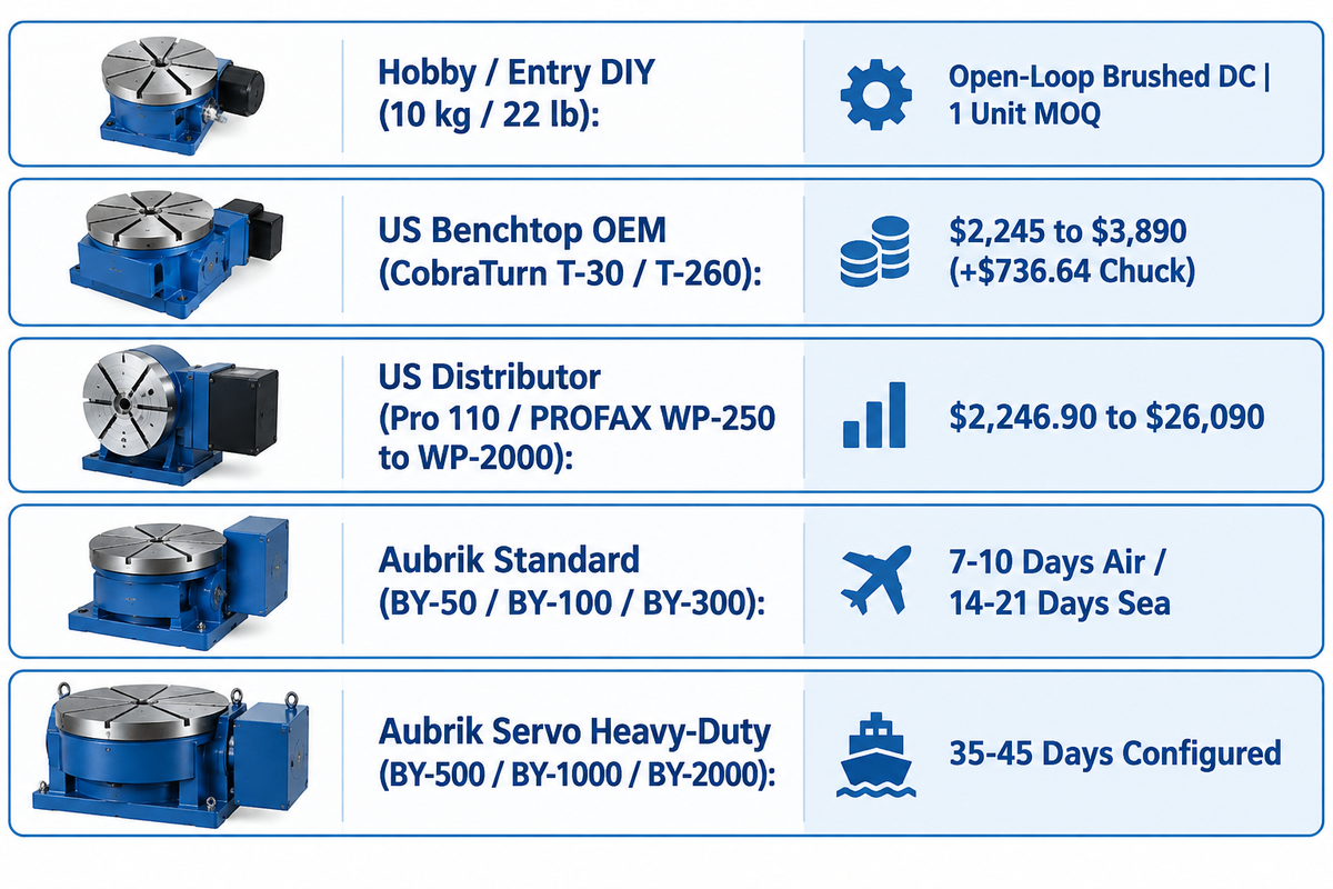
This guide groups rotary welding equipment into three pricing tiers: hobby, US benchtop, and heavy industrial. Entry-level import 10kg hobby tables and vevor rotary welding positioner units serve light diy welding and tacking. Made in the usa units, along with distributor-backed ones like the tig turret rotary weld positioner, offer high-quality bench performance.
Published US catalog prices on MK Products list the CobraTurn T-30 (30 lb) at $2,245 and the T-260 (260 lb) at $3,890. WeldingMart lists the 5-inch 3-jaw chuck (005-0812) at $736.64. On Arc-Zone, the Pro 110 lb positioner lists at $2,246.90–$2,939.80, and the 440 lb PROFAX WP-250 lists at $2,558.99–$3,936.99. On the same Arc-Zone catalog page, the 900 lb WP-500 lists at $7,474.99–$8,594.99, and the 3,500 lb WP-2000 lists at $21,100–$26,090. When shops motorize heavy pipe spools, industrial welding turntable units from Aubrik’s Wuxi facility cover the 50 kg to 2,000 kg BY-Series on a factory-direct quote basis. The facility operates under an ISO 9001:2015-certified quality management system. Complete package prices bundling a welding chuck, torch stand and pneumatic tailstock are quoted for each fixture configuration rather than published in fixed catalog bundles.
| Market Tier & Representative Models | Rated Horizontal Load | Published Price / Cost Structure | Drive & Runout Specification | Standard Lead Time & MOQ |
|---|---|---|---|---|
| Hobby / Entry DIY (10 kg Mini Tables) | 10 kg (22 lb) | Catalog retail varies by seller; request quote | Open-loop brushed DC motor; — | Parcel stock; 1 unit MOQ |
| US Benchtop OEM (MK Products CobraTurn T-30 / T-260) | 13.6 kg (30 lb) / 118 kg (260 lb) | $2,245 (T-30) / $3,890 (T-260); 3-jaw chuck $736.64 extra | Digital RPM display; 0–90° manual tilt; 5 in or 10 in table | Request distributor lead time; 1 unit MOQ |
| US Distributor Light-to-Heavy (Arc-Zone Pro 110 / PROFAX WP-250 to WP-2000) | 50 kg (110 lb) to 1,588 kg (3,500 lb) | $2,246.90–$2,939.80 (110 lb); $2,558.99–$3,936.99 (440 lb); $7,474.99–$26,090 (900–3,500 lb) | 0.5–8 RPM (Pro 110) or 0–5.5 RPM (WP-250); solid-state speed control | Request distributor lead time; 1 unit MOQ |
| Aubrik Factory-Direct Standard Bench & Shop (BY-50 / BY-100 / BY-300) | 50 kg / 100 kg / 300 kg | Factory-direct quotation (request quote by chuck and bore spec) | 0.5–5 RPM (BY-50) / 0.3–4 RPM (BY-100) AC stepless; ≤0.02 mm QC runout | 7–10 days air / 14–21 days sea; MOQ 1 unit |
| Aubrik Configured & Servo Heavy-Duty (BY-500 / BY-1000 / BY-2000) | 500 kg / 1,000 kg / 2,000 kg (5,000 kg custom) | Factory-direct quotation (request quote for DC servo option) | 0.1–2 RPM (BY-1000) / 0.08–1.5 RPM (BY-2000); 0–90° / 135° tilt; DC servo | 35–45 days configured; MOQ 1 unit |
Integration & Utility Requirements for Shop-Floor Commissioning
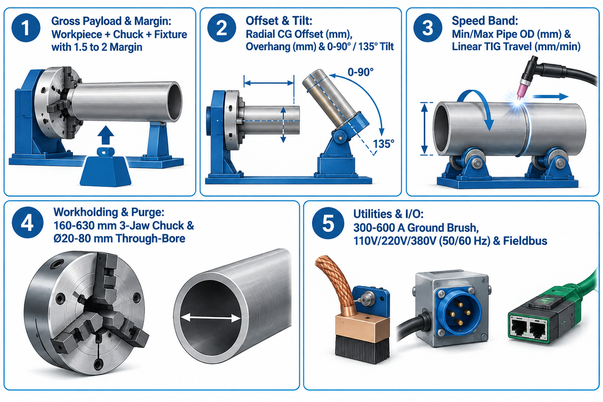
Before bolting a new positioner next to a shop welding table, maintenance teams should verify electrical power, grounding, and factory acceptance testing (FAT) paperwork. Aubrik builds BY-series turntables for variable 110V, 220V, or 380V (50/60 Hz) shop supplies. Drive motor power ranges from 25 W on the portable, lightweight BY-50 (with a compact design) up to 180 W on the heavy-duty BY-2000.
All electrical hookups must comply with OSHA 29 CFR 1910.304 grounding regulations alongside the dedicated rotary welding ground. The cited research reports ≤0.02 mm radial runout at 20–22 °C during a 24-hour stress test with a 1,800 kg load. Product CE conformity and ISO 9001:2015 quality-management documentation are maintained separately. Buyers can pair the checklist below with our welding positioner buyer RFQ and vendor-vetting playbook when issuing a purchase order.
Engineering RFQ & Commissioning Checklist for a TIG Turntable
- State the maximum workpiece weight plus the weight of the 3-jaw chuck and fixture, and apply a 1.5 to 2 payload margin for eccentric assemblies.
- State radial CG offset (mm) and axial overhang (mm). Specify 0° horizontal rotation (BY-50 to BY-500) or 0-90° / 135° motorized tilt (BY-1000 / BY-2000).
- Provide minimum and maximum pipe OD (mm) and linear TIG travel (mm/min). Use the RPM range to select the drive, with loaded low-speed regulation and angular positioning repeatability specified separately.
- Choose a self-centering 3-jaw chuck diameter (160-630 mm), adapter plate pattern, and a hollow, through-bore (Ø20-80 mm) for internal argon back-purging.
- Specify a 300–600 A rotary ground brush rating, shop voltage (110V / 220V / 380V, 50/60 Hz), foot pedal type, and robot communication interface.
Frequently Asked Questions
How do I calculate the right rotation speed (RPM) for a TIG turntable?
Divide your target linear TIG travel (in mm/min) by the workpiece circumference (π x outer diameter in mm). For example, welding a 168.3 mm outer-diameter stainless pipe at 110 mm/min requires 0.208 RPM. Match each travel-speed requirement to an individual turntable model whose rated continuous RPM range covers that speed.
Why does high-frequency TIG start cause erratic speed on a rotary welding positioner?
High frequency TIG arc initiation creates strong radio-frequency bursts that couple to unshielded circuit boards and foot pedals. Return current crossing ball bearings also causes micro-arcing. A rotary welding current return keeps welding current away from spindle bearings. Shielded control wiring and adequate bonding, along with ferrite beads, help to control HF interference.
What load capacity margin should I use when sizing a welding turntable for tilted pipe spools?
Use a 1.5x to 2x payload safety factor above combined weight of workpiece, chuck, and fixture for offset assemblies. At 90° tilt, gravitational force multiplied by radial CG offset gives the peak eccentric torque about the rotation axis. A tilt-axis torque requires a CG lever arm. Consider overhang bending moment and tilt-axis torque for offset assemblies.
How much radial runout is acceptable on a TIG welding turntable?
Aubrik reports a spindle radial runout of ≤ 0.02 mm (20 microns) as a factory QC specification. Workpiece runout at the weld joint includes chuck clamping and changes torch standoff during rotation.
When should I order a hollow-spindle TIG turntable instead of a solid-shaft table?
A hollow spindle turntable with a 20 mm to 80 mm through-bore can route an internal purge hose through the rotation axis. This reduces hose wrapping when welding stainless steel, duplex steel, or titanium tubing. This central bore is also helpful when passing long pipe spools straight through the centerline of chuck during continuous rotation. When back-purging reactive alloys, operators should pair the purge supply with internal purge dams, a sintered diffuser, and a sized exhaust vent.
What is the lead time and MOQ for an industrial BY-series welding turntable?
Standard Aubrik BY-50, BY-100 and BY-300 turntables ship in 7 to 10 days by air, or in 14 to 21 days by sea. The minimum order quantity is 1 unit.
Can a benchtop or heavy-duty TIG turntable integrate directly with a cobot or 6-axis welding robot?
For Aubrik BY-series integration with cobots such as the FANUC CRX series, 24V industrial I/O, TTL logic, and relay contacts require different electrical connections. For heavy multi-axis cells using FANUC R-2000iC or KUKA KR CYBERTECH robots, the servo-driven BY-1000 and BY-2000 models provide native PROFINET, Modbus TCP, and EtherNet/IP fieldbus interfaces. The fieldbus interfaces support communication between the turntable controller and the robot controller. Everything else including robot programming and signal mapping is still part of commissioning.
References & Sources
- Northcentral Technical College — Welding Fabrication & Robotics Associate Degree Curriculum (GTAW & Programmable Positioners)
- California Bureau for Private Postsecondary Education (BPPE) — Welding Positioner & GTAW Pipe Equipment Standards
- U.S. Occupational Safety and Health Administration (OSHA) — 29 CFR 1910.304 Wiring Design and Equipment Grounding Protection
- University of Guelph Department of Physics — Torque and Rotational Motion Vector Tutorial
- National Center for Biotechnology Information (PMC / NIH) — ISO 9283 Industrial Manipulator Positioning Accuracy and Repeatability Evaluation
- National Center for Biotechnology Information (PMC / NIH) — Performance Criteria and Environmental Test Conditions in ISO 9283
- American Welding Society (AWS) — AWS D1.1/D1.1M Structural Welding Code — Steel
- American National Standards Institute (ANSI) — AWS D1.1/D1.1M:2025 Structural Welding Code – Updates
- MDPI Materials — Circumferential Pipe Welding Bead Uniformity and Rotational Positioning
- PubMed/National Library of Medicine — Effect of Gravitational Orientation on Bead Geometry in Multi-Pass Orbital GTAW
- Google Patents — CN103600196A Welding Positioner Control System
Trending now