Get in Touch with Aubrik Company

Updated October 2026 Engineering Sizing Guide by Wuxi ABK Machinery (Aubrik)
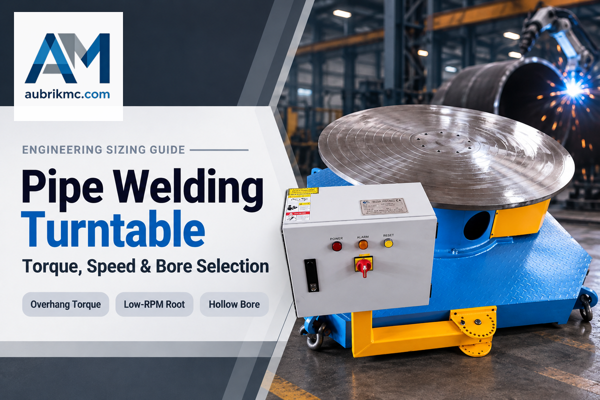
A pipe welding turntable is a motorized rotary welding table that spins flanged stubs, valve bodies, and pipe spools around a vertical or 0 to 90 degree tilted axis for flat 1G or horizontal 2G welding. Standard Aubrik BY-Series models span 50 to 2,000 kg gross loads, 0.08 to 5 rpm speeds, and optional 20 to 80 mm argon-purge bores. Custom flatbeds exceed 5,000 kg, and heavy pipe positioners reach 50,000 kg.
Quick Engineering Thresholds for Pipe Spool Selection
- Flanged stubs, valve bonnets, and dogleg tees from 50 to 2,000 kg fit BY-Series turntables. Straight shells above a 4:1 length-to-diameter ratio are usually run on turning rolls.
- Center-of-gravity overhang torque must not exceed gearbox limits (up to 500 N·m on heavy BY-Series drives) after applying a gross-load safety margin of 1.25x to 2.0x.
- Low-end gearbox speed governs large-bore GTAW roots because light 0.5 to 5 rpm benchtop drives can’t drop down to sub-0.2 rpm pipe procedures.
- Copper shielded 160 to 630 mm 3-jaw chucks pair with hollow spindles and 200 to 500 A rotary ground paths on stainless and high-amp spools.
When to Use a Pipe Welding Turntable vs. Turning Rolls and Tilting Welding Positioners
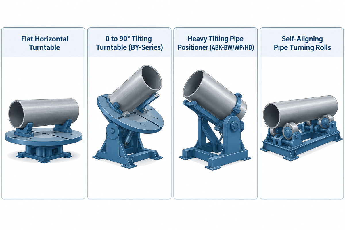
Standard BY-Series pipe welding turntable frames can handle spools from 50 to 2,000 kg. Each flanged pipe piece locks concentrically inside a 3-jaw chuck on one end. Turning rolls are generally used on pipes and shells of a length to diameter ratio of 4:1 or more. Overhung or eccentric spools are balanced by a properly sized positioner, and heavier straight spools can be balanced by a turning roll.
Shop managers often ask why existing roller beds or manual V-stands fail on custom spool assemblies. Friction rolls require continuous, concentric contact along two clean cylinder rings. Dogleg elbows and olets on pipes lift the pipe off the polyurethane tire and stall rotation. Balanced flat plate weldments and symmetrical drums, in rotary welding positioners and turntables, are supported on standard faceplates. Eccentric pipe branches, however, alter drive torque on every turn.
On a horizontal faceplate turntable spinning around a vertical axis, gravity acts straight down into the main thrust bearing. An off-center tee branch creates minimal variable drive torque during the 360 degree weld. If that same dogleg spool is tilted 90 degrees, the tee branch becomes an uphill and downhill pendulum. Don Burgart notes in The Fabricator’s Engineering review of industrial positioneering, that floor turntables across heavy fabrication span 250 to 40,000 lb. In Aubrik’s catalog, the 1,000 to 2,000 kg band overlaps between heavy BY-Series turntables (up to 500 N·m torque) and ABK-BW units. High moment tilted spools step up to tilting pipe welding positioners rated from 1 to 50 tons (ABK-BW, ABK-WP, and ABK-HD series).
The 3-Axis Pipe-to-Positioner Crossover Rule
- Flat horizontal turntables (vertical axis, 2G or flat-end 1G) hold short pipe-to-flange necks, valve bonnets, and dogleg tees from 50 to 2,000 kg. Gravity is aligned with the spindle axis.
- Tilting 0 to 90 degree turntables (BY-1000 and BY-2000 as standard; smaller sizes need a custom tilt option) fit butt and mitered fillet welds on compact spools. Overhang torque should be within the limits of the BY-Series (up to 500 N·m).
- Heavy pipe positioners (0 to 135 degrees) of 1 to 50 tons carry tilted eccentric spools that exceed turntable moment ratings. Branch-free shells of 4 or more diameters run on turning rolls.
| Rotary Architecture | Axis Motion & Weld Position | Typical Gross Load Band | Pipe Geometry & L/D Limit | Primary Disqualifier |
|---|---|---|---|---|
| Flat Horizontal Turntable | 360° vertical-axis spin (2G horizontal / flat end) | 50 to 2,000 kg (custom 5,000+ kg) | Short flanged stubs, valve bodies, wide dogleg tees | Cannot tilt horizontal pipe axis into downhand 1G groove |
| 0 to 90° Tilting Turntable (BY-Series) | 360° spin + 0 to 90° tilt (1G / 2G / 45° fillet) | 1,000 to 2,000 kg standard (de-rated at 90° tilt); custom tilt on smaller sizes | 1.5 to 16 in. spools; L/D > 3 needs outboard stand | Tilted eccentric moment above BY drive rating (up to 500 N·m) |
| Heavy Tilting Pipe Positioner (ABK-BW/WP/HD) | 360° VFD spin + 0 to 135° sector/hydraulic tilt | 1,000 to 50,000 kg (1 to 50 t; overlaps 1 to 2 t high-moment) | 40 to 2,500 mm OD thick-wall spools and headers | Excessive floor footprint and capital cost for light tube work |
| Self-Aligning Pipe Turning Rolls | Horizontal-axis friction roller drive (1G roll) | 2,000 to 200,000+ kg | Long straight pipes, shells, and pressure vessels (L/D > 4) | Branches, couplings, or short stubs break wheel contact and walk |
When Are Pipe Welding Turntables Used Instead of Pipe Rotators?
Substitute welding turntables for pipe rotators when protruding branches, slip-on flanges, reducer cones, or short stubs with a length-to-diameter ratio less than 4:1 interrupt continuous roller contact. That positive clamp stops the axial creep and wheel slip seen on friction rollers.
For straight 6 to 12 meter pipe joints and cylindrical tank shells, self-aligning pipe welding rotators and turning rolls equally distribute weight without cantilever stress. For long flanged spools that require positive chuck indexing, fabricators clamp the flange end on a horizontal axis turntable. A passive outboard roller stand or a synchronized tailstock, then, supports the free barrel.
Sizing a Rotary Welding Positioner Table: Load Rating, Overhang Moment, and Pipe RPM Math
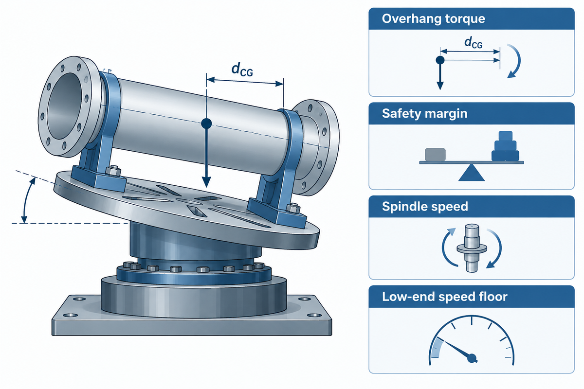
The RPM of the spindle is determined by dividing qualified WPS travel speed by pipe circumference. Add chuck and purge-fixture mass to the heaviest spool before checking the manufacturer’s 0 to 90 degree overhang torque chart, and verify the reducer reaches your slowest root-pass speed without motor cogging.
Two checks, mechanical torque capacity and low-end rotational frequency, influence all purchases of pipe turntables. Faceplate payload ratings are valid only when the center of gravity sits near the flat 0 degree table face. Tilting the table to 90 degrees magnifies vertical static gravitational torque by overhang distance. Jason Ladd of Koike Aronson, shows in The Welder’s guide to weld positioner sizing that a 50 lb weldment at 3 inches overhang creates 12.5 ft-lb of torque. Extending that offset to 6 inches doubles the vertical torque load to 25 ft-lb.
Gravitational torque (M) follows the equation M = W × g × d_CG. Here W is combined spool, chuck, and fixture mass in kilograms, g is 9.81 m/s², and d_CG is horizontal center-of-gravity overhang in meters. Static math omits start-stop indexing inertia, eccentric tee imbalance, 3-jaw chuck grip limits, and cross-roller bearing stiffness. Use a 1.25x minimum safety margin (Aubrik BY-Series sizing baseline) and up to 2.0x on asymmetric elbows, with torque kept within the manufacturer’s moment curves. Keep torque within the moment curves of the manufacturer.
In kinematic terms, spindle speed follows the equation RPM = v / (π × OD), where WPS travel speed in mm/min is divided by the pipe’s circumference. Travel speed also enters linear arc energy alongside current, voltage, and thermal efficiency under CEN EN 1011-1:2009 general guidance for arc welding. Our welding positioner RPM and surface travel speed calculator takes the pipe’s outside diameter and process speed and converts them directly to spindle RPM.
Worked Sizing Calculation: 6-Inch Schedule 40 Stainless Tee Spool (168.3 mm OD)
- Combining the 42 kg 316L pipe piece, 28 kg 300 mm 3-jaw chuck, and 8 kg purge dam yields 78 kg gross mass. Applying the 1.25x safety factor sets a 97.5 kg minimum capacity floor.
- At a 120 mm (0.12 m) horizontal CG offset in 90 degree tilt, static torque M = 78 kg × 9.81 m/s² × 0.12 m = 91.8 N·m. A 1.25x dynamic margin brings total moment to 114.8 N·m, inside the 500 N·m rating of heavy-duty BY-Series variants; check the rating of the exact model quoted.
- For this illustrative 168.3 mm OD pipe, circumference equals π × 168.3 mm = 528.7 mm. Dividing by 528.7 mm gives 0.14 rpm for a 75 mm/min GTAW root and 0.53 rpm for a 280 mm/min GMAW cap. Mechanized FCAW or SAW procedures at 400 to 600 mm/min run higher at 0.76 to 1.13 rpm on that 528.7 mm circumference.
- A 100 kg BY-100 handles static weight, yet its 0.3 to 4 rpm motor floor turns about 2x too fast for 0.14 rpm TIG roots. A BY-1000 (0.1 to 2 rpm) covers the 0.14 rpm root at 75 mm/min directly. Meanwhile, a BY-500 (0.15 to 2 rpm) fits 6-inch roots qualified at 80 mm/min or faster.
| Nominal Pipe Size (ASME Sch 40) | Outside Diameter & Circumference | Manual GTAW Root (75 to 120 mm/min) | GMAW Fill / Cap (250 to 320 mm/min) | Minimum Aubrik BY Speed Tier |
|---|---|---|---|---|
| 1.5 in. Pipe | 48.3 mm OD (151.7 mm circ.) | 0.49 to 0.79 rpm | 1.65 to 2.11 rpm | BY-50 (0.5 to 5 rpm) or BY-100 (0.3 to 4 rpm) |
| 2 in. Pipe | 60.3 mm OD (189.4 mm circ.) | 0.40 to 0.63 rpm | 1.32 to 1.69 rpm | BY-100 (0.3 to 4 rpm) |
| 3 in. Pipe | 88.9 mm OD (279.3 mm circ.) | 0.27 to 0.43 rpm | 0.90 to 1.15 rpm | BY-300 (0.2 to 3 rpm) |
| 4 in. Pipe | 114.3 mm OD (359.1 mm circ.) | 0.21 to 0.33 rpm | 0.70 to 0.89 rpm | BY-300 (0.2 to 3 rpm) |
| 6 in. Pipe | 168.3 mm OD (528.7 mm circ.) | 0.14 to 0.23 rpm | 0.47 to 0.61 rpm | BY-1000 (0.1 to 2 rpm; BY-500 at ≥80 mm/min) |
| 8 in. Pipe | 219.1 mm OD (688.3 mm circ.) | 0.11 to 0.17 rpm | 0.36 to 0.46 rpm | BY-1000 (0.1 to 2 rpm) |
| 10 in. Pipe | 273.1 mm OD (858.0 mm circ.) | 0.09 to 0.14 rpm | 0.29 to 0.37 rpm | BY-2000 (0.08 to 1.5 rpm; BY-1000 stops at 0.1 rpm) |
| 12 in. Pipe | 323.9 mm OD (1,017.6 mm circ.) | 0.08 to 0.12 rpm (at 80 to 120 mm/min) | 0.25 to 0.31 rpm | BY-2000 (0.08 to 1.5 rpm; BY-1000 stops at 0.1 rpm) |
| 16 in. Pipe | 406.4 mm OD (1,276.7 mm circ.) | 0.06 to 0.09 rpm (at 80 to 120 mm/min) | 0.20 to 0.25 rpm | ABK-BW Pipe Positioner (0.02 to 1.2 rpm) |
Notice the 35:1 speed turndown span from a 1.5-inch GMAW cap pass (2.11 rpm) down to a 16-inch manual TIG root (0.06 rpm). Your shop’s qualified WPS travel speed range determines the reducer ratio before ordering a single-ratio reducer.
What Size Pipe Welding Turntable Do I Need for Overhung Spools?
Pick a turntable whose rated tilting torque exceeds the total weight force multiplied by horizontal center-of-gravity offset from the tilt axis, plus a 1.25x to 2.0x safety margin. Several catalog models of pipe turntables show that the horizontal faceplate load drops by 50% when the overhang load shifts off the faceplate.
Baileigh’s WP-750 drops from 770 lb vertical-axis capacity to 385 lb at 90 degree horizontal tilt, and MAC’s PS-1F-5-A drops from 200 lb flat to 100 lb at a 2-inch CG offset. Our overhang center-of-gravity load capacity calculator uses spool length, flange mass, and elbow offset to size the frame.
Benchtop Rotary Table vs. Floor-Mount Turntables for Pipe Shop Fabrication
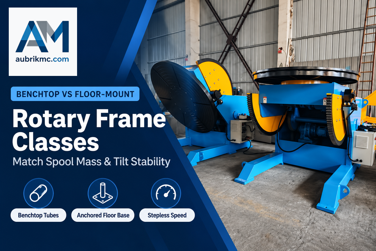
Portable benchtop rotary tables handle 50 to 300 kg sanitary tubes and valve fittings on 200 to 320 mm faceplates with 25 to 60 W motors. Anchored floor-mount turntables carry 500 to 2,000 kg Schedule 40 and 80 spools on 400 to 600 mm tables with 90 to 180 W drives.
Crane-hook clearance, tilt angle, and spindle stiffness separate benchtop frames from floor-mounted turntables. Keith Honhart of Atlas Welding Accessories notes in The Fabricator’s guide to benchtop tube and pipe positioners that centered loads from 50 to 250 lb suit compact bench units. On those frames, a 45 degree tilt positions pipe-to-flange fillet joints downhand, while a 90 degree tilt handles butt welds on each fitting component. Mitrowski Welding lists benchtop models in this band, including the 200 lb MBC BP-2, 250 lb Profax WP-250, and 350 lb Pandjiris Mini Pro.
Above 300 kg, unbolted bench frames risk tipping under cantilevered pipe loads and often lack ultra-low RPM gearing. Aubrik builds industrial welding turntables in the 50 kg to 2,000 kg range (customizable to 5,000+ kg capacity), with 200 to 600 mm table diameters and stepless rotational bands from 0.5 rpm to 5 rpm (BY-50) down to 0.08 rpm to 1.5 rpm (BY-2000). Thermally stabilized BY-Series frames hold radial runout within ≤0.02 mm on bench inspection.
| Model Tier | Mounting Class | Rated Horizontal Capacity | Table Diameter & Drive Power | Spindle Speed Range | Typical Pipe Spool Duty |
|---|---|---|---|---|---|
| Aubrik BY-50 | Benchtop | 50 kg (110 lb) | Ø200 mm · 25 W | 0.5 to 5 rpm | 0.5 to 1.5 in. sanitary dairy/pharma tube fittings |
| Aubrik BY-100 | Benchtop | 100 kg (220 lb) | Ø250 mm · 40 W | 0.3 to 4 rpm | 1 to 2.5 in. stainless instrumentation & flange necks |
| Aubrik BY-300 | Heavy Bench / Pedestal | 300 kg (660 lb) | Ø320 mm · 60 W | 0.2 to 3 rpm | 2 to 4 in. Schedule 40 spools & hydraulic manifolds |
| Aubrik BY-500 | Floor-Mount | 500 kg (1,100 lb) | Ø400 mm · 90 W | 0.15 to 2 rpm | 4 to 6 in. process pipe spools & ANSI valve bodies |
| Aubrik BY-1000 | Floor-Mount | 1,000 kg (2,200 lb) | Ø500 mm · 120 W | 0.1 to 2 rpm | 6 to 12 in. Schedule 40/80 stainless & alloy spools |
| Aubrik BY-2000 | Floor-Mount | 2,000 kg (4,400 lb) | Ø600 mm · 180 W | 0.08 to 1.5 rpm | Heavy flanged tees, pump casings & cobot spool cells |
| Aubrik BY-Custom | Anchored Floor Flatbed | 5,000+ kg (11,000+ lb) | Custom Faceplate · VFD/Servo | Custom low-RPM ratio | Vertical-axis cladding, turbine rings & large flanges |
| Aubrik ABK-BW Series | 0 to 135° Pipe Positioner | 1,000 to 5,000 kg (1 to 5 t) | Pipe OD 40 to 660 mm · VFD | 0.02 to 1.2 rpm | Medium-heavy tilted pipe spools exceeding BY torque limits |
| Aubrik ABK-WP Series | Heavy Gear/Hydraulic Positioner | 6,000 to 20,000 kg (6 to 20 t) | Pipe OD 200 to 1,600 mm | 0.02 to 1.2 rpm | Process headers, large elbows & thick-wall pipe spools |
| Aubrik ABK-HD Series | Extra-Heavy Hydraulic Positioner | 25,000 to 50,000 kg (25 to 50 t) | Pipe OD 600 to 2,500 mm | 0.02 to 1.2 rpm | Refinery headers, offshore risers & heavy vessel nozzles |
3-Jaw Self-Centering Chucks, Through-Bore Spindles, and Argon Back-Purge Weld Setup
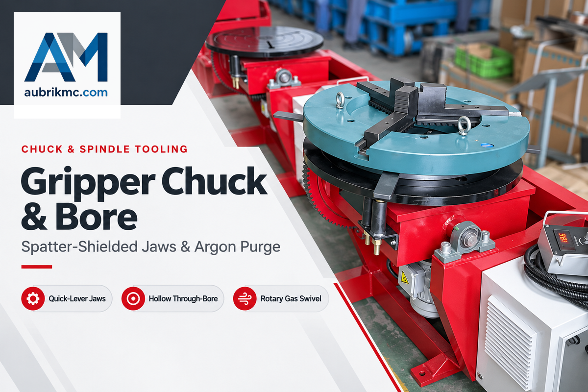
Equip the turntable faceplate with a quick-clamp 3-jaw welding gripper chuck (160 to 630 mm clamping range across BY-Series options) instead of a machine-tool lathe chuck. Size the hollow through-bore spindle (an Ø20 to 80 mm option on selected BY models) larger than the purge hose or pass-through pipe outside diameter, and confirm exact chuck-to-bore mounting dimensions on the manufacturer’s model drawing.
First-time buyers will often mount a lathe scroll chuck onto a rotary table to cut tooling costs. Within weeks, arc spatter hardens the scroll plate and jams the jaws. Dedicated welding gripper chucks use enclosed scroll tracks, copper-shielded jaw slides, and quick-lever cam handles. Reversible stepped jaws allow it to switch between internal flange bores and external pipe walls.
Purge hose routing dictates spindle design on austenitic stainless, duplex, and nickel-alloy roots requiring inert backing per WPS (unlike qualified flux-backed root wires). A solid-shaft table blocks a through-spindle purge path, requiring hoses to wrap around the pipe. A hollow through-bore spindle (Ø20 to 80 mm option on selected Aubrik BY models; 1-1/8 to 2-1/2 in. on Profax WP-250, Bancroft TT500, and Pandjiris Mini Pro) feeds gas straight through a rotary swivel union.
Argon purge flow that’s too fast draws in ambient air through the open root gap and contaminates the weld zone. In WIPO Patent WO2020033478A1 on pipe welding gas purging, flowing controlled purge gas into sealed pipe assemblies and monitoring discharged exhaust outlet gas concentration establishes the pre-weld purge window before closing the root keyhole. Keep the internal purge flow laminar and slightly positive until the root and hot passes seal the joint.
| Published Model / Series | Rated Load Class | Published Hollow Spindle Bore | Compatible Chuck / Faceplate | Argon Back-Purge Routing Fit |
|---|---|---|---|---|
| Profax WP-250 | 250 lb (113 kg) vertical | 1-1/8 in. through-hole | Optional 8 in. (200 mm) gripper chuck | Through-spindle argon hose + small tube pass-through |
| Pandjiris Mini Pro | 350 lb (159 kg) vertical | 2 1/2 in. through-hole | Benchtop slotted faceplate + 3-jaw chuck | Rotary gas swivel union feeding internal purge dam |
| Bancroft TT500 | 500 lb (227 kg) vertical | 2 in. (50.8 mm) hollow spindle | 12 in. faceplate + heavy 3-jaw chuck | High-flow diffuser + dual-seal purge bladder supply |
| Aubrik BY-Series (BY-50 to BY-2000) | 50 to 2,000 kg horizontal | Ø20 to 80 mm center-hole option on selected models | 160 to 630 mm 3-jaw welding chucks (Ø200 to 600 mm tables) | Matched per spool OD, chuck mass & inert-gas root WPS |
Rotary Ground Current Return, High-Frequency TIG Shielding, and Bench Application Limits
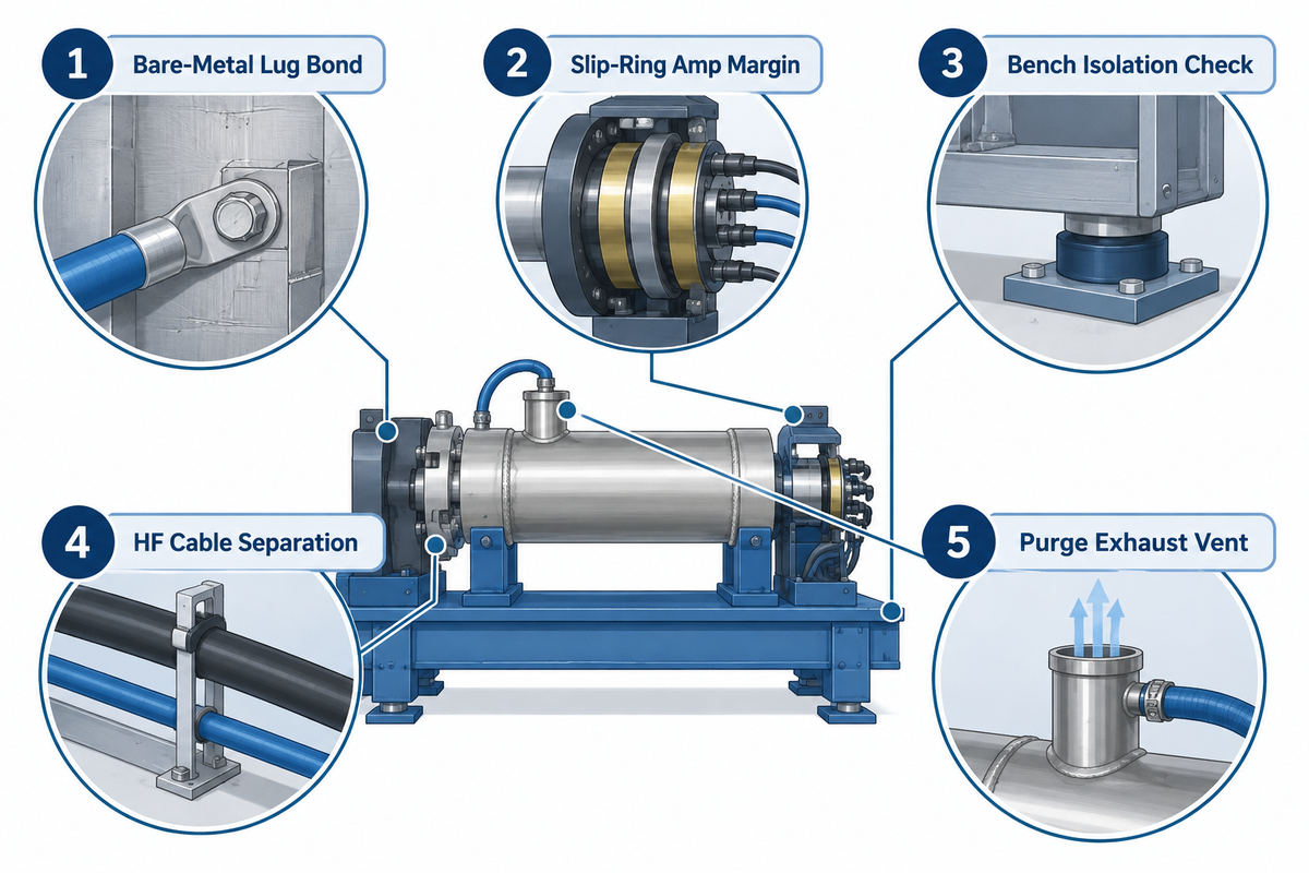
When the 3-jaw chuck and hollow spindle are mounted, clamp the welding return lead to a dedicated rotary ground lug. Never ground through a stationary turntable base or steel workbench without a rotary brush rated above peak current. Stray return current pits spindle bearing raceways and unshielded high-frequency TIG starts destroy low-cost speed controllers.
In U.S. general-industry fabrication shops, arc welding return circuits fall under OSHA 29 CFR 1910.254 arc welding and cutting regulations. Field construction sites follow 29 CFR 1926.351(c). Clause 1910.254(c)(2)(ii) bars using electrical conduits or gas and flammable-liquid pipelines as permanent return paths. Clauses 1910.254(c)(2)(iv) and (v) govern welding fixtures used in current return circuits:
“Where a structure, conveyor, or fixture is regularly employed as a welding current return circuit, joints shall be bonded or provided with adequate current collecting devices. All ground connections shall be checked to determine that they are mechanically strong and electrically adequate for the required current.”
Source: U.S. OSHA 29 CFR 1910.254(c)(2)(iv), (v) (General Industry)
At the equipment level, separate from OSHA’s facility-piping rule, welders on bench setups often bolt a rotary unit onto a grounded steel welding bench and clip the work lead to the bench corner. Keith Honhart warns in The Fabricator’s benchtop positioner analysis that high-amperage ground current then flows straight through the spindle bearings to reach the bench. Microscopic arcs pit the bearing rollers and cause jerky rotation that ruins bead uniformity. Industrial turntables bypass the bearings via spring-loaded copper-graphite slip rings or rotary brushes rated from 200 to 500 A (300 A on Bancroft’s TT100 and 500 A on the TT500).
| Check Step | Physical Inspection Point | Pass Criterion | Failure Consequence if Skipped |
|---|---|---|---|
| 1. Bare-Metal Lug Bond | Rotary ground lug & chuck mounting face | Paint and mill scale stripped clean; tight bolt torque | High contact resistance heats lug and causes arc wander |
| 2. Slip-Ring Amp Margin | Copper-graphite rotary brush assembly | Rated ≥200 A for light TIG; 300 to 500 A for pulsed MIG/SAW | Stray current shunts through spindle bearings and flutes races |
| 3. Bench Isolation Check | Turntable base vs. grounded steel workbench | Work return cable clamped directly to turntable ground lug | Return current loops through motor housing or control board |
| 4. HF Cable Separation | TIG torch lead vs. foot-pedal & VFD cables | Keep TIG torch leads physically separated from foot-pedal and VFD cables; never coil together | HF arc initiation induces voltage spikes into speed controller |
| 5. Purge Exhaust Vent | Outboard purge dam vent vs. spindle inlet | Unobstructed vent limits pressure buildup while maintaining slight positive purge flow | Excessive internal gas pressure blows pinholes in final root closure |
Are Pipe Welding Turntables Safe for High-Frequency TIG Start?
Industrial pipe welding turntables help reduce high-frequency TIG arc-start interference when built with RF-filtered power inputs, shielded electric motor cables, isolated 24 V control transformers, and verified protective earthing. Unshielded hobby PWM DC motor boards frequently fail or jump to runaway full speed during HF ignition.
To improve accuracy on thin-wall stainless tube welds, bond the metal enclosure to a dedicated earth rod or verified shop ground bus. Keep the GTAW torch hose physically separated from the remote hand pendant and foot switch. That physical separation keeps spindle speed accurate during arc initiation.
Drive Mechanics and Speed Control: VFD Gear Drives vs. Servo Turntables for Robotic Cells
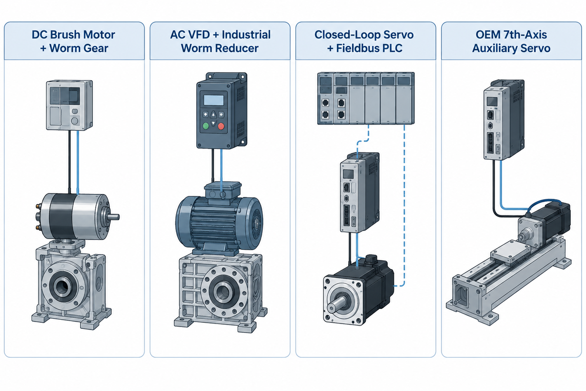
AC variable-frequency worm-gear drives with foot-pedal or remote hand controls handle continuous manual circumferential pipe welding at the lowest cost. For multi-pass indexed spools and automated cobot cells requiring closed-loop AC servo drives, encoder-verified angular indexing or PLC handshake control is used by the weld cell.
Automation engineers integrating a rotary axis into a robotic or cobot pipe cell choose between two control architectures. The first option is discrete PLC or fieldbus indexing. Aubrik runs AC drives on the BY-50 through BY-500 and DC servo drives on the BY-1000 and BY-2000, which add PROFINET, Modbus TCP, and EtherNet/IP; all six BY models accept low-voltage TTL signals. By contrast, standard catalog sheets from Profax, Bancroft, and Pandjiris list 1-1/8 to 2-1/2 inch through-holes without published robot fieldbus protocols. Under ISO 9283 manipulator pose repeatability test methods analyzed in Machines, closed-loop servo repeatability on industrial manipulators is tested at benchmarks such as ±0.1 mm over 30 cycles. Actual turntable indexing tolerances still depend on pipe joint fit-up and seam tracking.
The second option is native 7th-axis coordinated kinematic interpolation, which requires an auxiliary servo motor and drive matched to the specific robot controller. That coordinated servo axis moves simultaneously with all six arm joints along saddle-cut pipe branches; see synchronized robotic welding cells with auxiliary rotary axes. Cobots (such as Novarc’s 2 to 60 inch spool welding cells) with twin-station rotary tables cut part-handling idle time. In automated rotary welding cell comparisons, twin-station setups raise arc-on robot utilization from 60–70% to 85–95%.
| Drive Architecture | Speed & Position Control | Repeatability & Backlash | Best Pipe Fabrication Fit |
|---|---|---|---|
| DC Brush Motor + Worm Gear | Dial potentiometer + start/stop foot pedal | Open-loop; speed sags under eccentric load | Light concentric tube tacking & single-pass bench work |
| AC VFD + Industrial Worm Reducer | Digital RPM display, remote hand box & foot switch | ≤0.02 mm radial runout; self-locking worm gear | Manual GTAW/GMAW Schedule 40/80 circumferential spools |
| Closed-Loop Servo + Fieldbus PLC | PROFINET, Modbus TCP, EtherNet/IP or 24V/TTL I/O | Encoder-verified indexing; repeatability tested per ISO 9283 methods | Cobot pipe spool cells & multi-pass indexed flanges |
| OEM 7th-Axis Auxiliary Servo | Robot controller real-time kinematic interpolation | Low-backlash RV or harmonic reducer matched to robot arm | 3D pipe-to-pipe saddle branches (often lacks hollow bore) |
DIY Drill-Motor Builds and Used Units vs. Industrial Pipe Welding Turntables
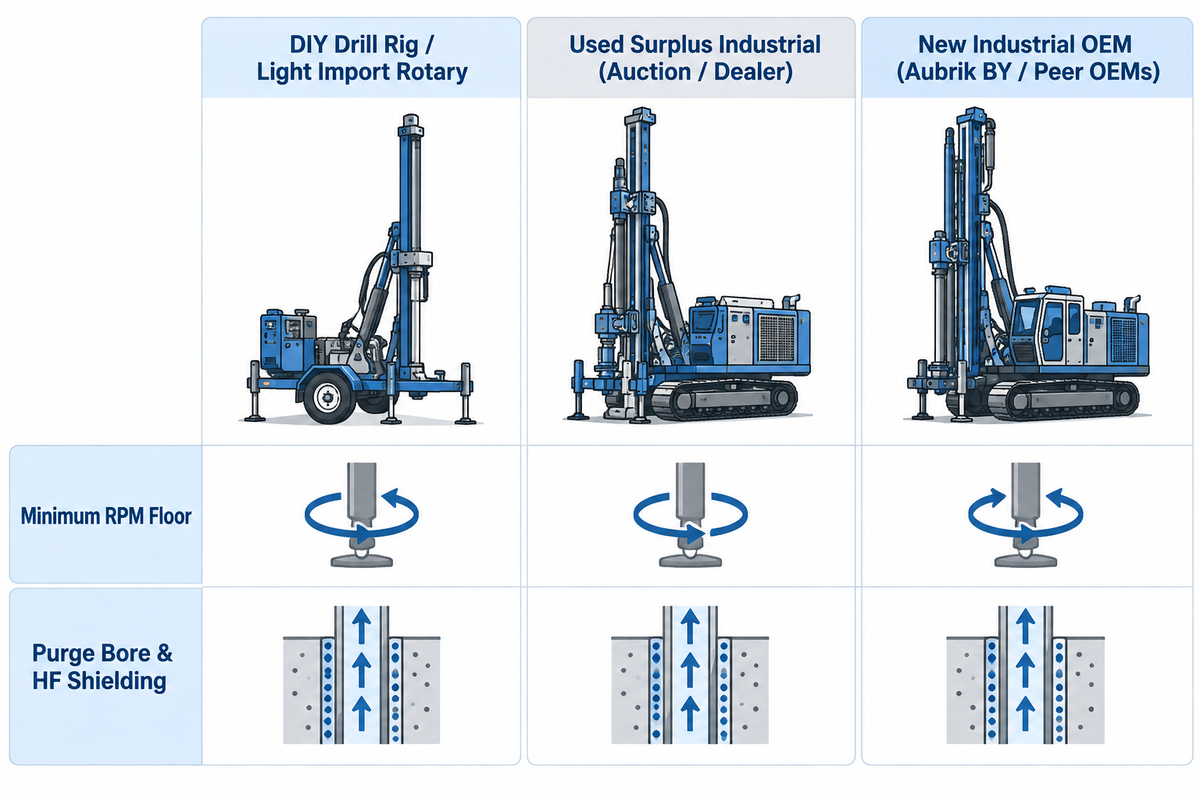
Entry-level 7.5-inch hobby rotary imports and home cordless-drill builds fail on open-root pipe TIG welding where steady low-speed travel is critical. Their 2 rpm minimum speed floor drives travel speed past manual fusion, and unshielded low-voltage DC motor cogging causes heat build-up.
A 2 rpm minimum floor on an entry-level eBay hobby rotary table drives a 6-inch Schedule 40 stainless pipe (528.7 mm circumference) at 1,057.5 mm/min (41.6 in./min). That speed runs more than seven times faster than a standard 75 to 150 mm/min manual open-root GTAW window. Mechanized GMAW fill passes on 6-inch spools run 250 to 320 mm/min, still less than one-third of that 2 rpm surface speed.
Dimming an uncompensated DC motor down near stall causes torque cogging, especially if there’s an off-center pipe elbow climbing uphill. With arc current and voltage held constant, linear heat input increases inversely as travel speed decreases. A sudden 20% speed drop during cogging spikes local heat input by 25% (1 / 0.80 = 1.25). That increased heat input blows a keyhole straight through a thin root face of the stainless steel.
| Evaluation Criterion | DIY Drill Rig / Light Import Rotary | Used Surplus Industrial (Auction / Dealer) | New Industrial OEM (Aubrik BY / Peer OEMs) |
|---|---|---|---|
| Market Price Reference | Unrated hobby import or DIY shop build using scrap parts | $5,999 to $9,500 on Surplus Record (Pandjiris 15-4 $5,999; Readco UPC-25 $9,500) | Quoted via RFQ by spec ($1,580 to $6,200 across Bancroft TT100 to TT500 catalog) |
| Minimum RPM Floor | Often ≥2.0 rpm minimum (1,057.5 mm/min on 6 in. pipe; too fast for TIG roots) | 0.1 to 0.5 rpm (legacy SCR cards prone to thermal speed drift) | 0.08 to 0.5 rpm stepless VFD or closed-loop servo |
| Purge Bore & HF Shielding | Solid shaft; unshielded PWM board fries under HF TIG | Model-dependent; rotary carbon brushes often worn out | Optional Ø20 to 80 mm bore + shielded enclosure + 200 to 500 A brush |
Can Used Pipe Welding Turntables Be Repaired for Code Pipe Work?
Heavy cast-iron used turntables from legacy builders like Ransome, Pandjiris, or Koike Aronson can be rebuilt for code pipe welding, as long as spindle bearing seats stay concentric. A reliable rebuild would replace pitted bearings and worn bronze worm wheels and also replace speed cards with a shielded AC VFD drive.
Surplus machinery needs radial spindle-play measurement with a dial indicator and replacement rotary ground blocks priced before bidding. Where a fabrication shop’s quality program applies EN ISO 17662:2025 welding equipment verification, technicians verify travel speed with a stopwatch and a tape measure or steel rule after drive rebuilds.
Pipe Welding Turntable Price Tiers, Lead Times, and Manufacturer RFQ Evaluation
Published North American prices run $1,580 to $2,804 for 100 to 200 lb (45 to 91 kg) benchtop units and $4,790 to $6,200 for 200 to 500 lb (91 to 227 kg) manual-tilt models (Bancroft Engineering and Surplus Record). Heavy surplus positioners and servo stations span $9,500 to $29,500, while metric 50 to 2,000 kg OEM turntables quote via RFQ across 14 to 90 day lead-time tiers.
Separate bare-faceplate base quotes from complete pipe-ready packages when comparing market offers. Adding a 7-inch (180 mm) gripper chuck lifts an MBC BP-2 (200 lb / 91 kg) benchtop unit from $2,014 bare to $2,804. U.S. manual tilting units put Bancroft’s TT100 (100 lb / 45 kg) at $1,580, TT212 (200 lb / 91 kg) at $4,790, and TT500 (500 lb / 227 kg vertical rating, 2-inch bore) at $6,200, while 450 to 1,100 lb Baileigh Industrial rotary models list online, from $2,914.00 for the 110V WP-450 to $6,841.00 for the WP-1100. Surplus Record also lists a Pandjiris 15-4 at $5,999, a 2,500 lb Readco UPC-25 at $9,500, and a Fronius International FRT150 servo station at $29,500. Jason Ladd notes in The Fabricator’s buyer checklist that specifying plant voltage and fixture weight upfront prevents costly retrofits.
Sourcing factory-direct from Wuxi ABK Machinery (Aubrik, est. 1999) requires a minimum order quantity (MOQ) of 1 standard unit. Pricing is given per voltage, chuck size and bore diameter. In-stock benchtop models (BY-50, BY-100, BY-300) ship in 14-21 day sea windows or 7-10 day air shipments. Configured floor-mount units (BY-500, BY-1000, BY-2000) build in 35-45 day schedules, custom 5,000 kg or robotic stations take 60-90 day lead-time tiers, and spare wear parts dispatch within 5 to 7 business days.
| Published North American Catalog Class | Verified North American Price Reference | Nearest Metric Aubrik Series (MOQ 1 Unit) | Aubrik Indicative Lead Time |
|---|---|---|---|
| 100 to 200 lb US Benchtop (45 to 91 kg) | $1,580 to $2,804 (Bancroft TT100 $1,580; MBC BP-2 $2,014 bare / $2,804 w/ chuck) | BY-50 (50 kg) / BY-100 (100 kg) — quoted via RFQ | 14 to 21 days sea · 7 to 10 days air |
| 200 to 500 lb US Manual-Tilt (91 to 227 kg) | $4,790 to $6,200 at Bancroft (TT212 200 lb $4,790; TT500 500 lb $6,200) | BY-300 (300 kg) / BY-500 (500 kg) — quoted via RFQ | 14 to 21 days (BY-300) · 35 to 45 days (BY-500) |
| 2,500 lb Surplus Floor Class (1,134 kg) | Readco UPC-25 listed at $9,500 on Surplus Record; new heavy OEM via RFQ | BY-1000 (1,000 kg) / BY-2000 (2,000 kg, up to 500 N·m) — via RFQ | 35 to 45 days configured build |
| Robotic Servo / Custom 5,000+ kg Flatbed | Fronius FRT150 servo station at $29,500 on Surplus Record; custom cells via RFQ | BY-Custom (5,000+ kg) / PROFINET or Modbus Servo Station | 60 to 90 days engineered build |
Pipe Welding Turntable RFQ Specification Checklist (Copy Into Purchase Inquiry)
Include spool mass, center-of-gravity overhang, WPS speed window, chuck bore, peak current, control interface, and shop voltage so the manufacturer sizes the drive on the first quote.
| RFQ Parameter | What to Specify | What Fails on the Shop Floor If Omitted |
|---|---|---|
| 1. Spool Envelope & Gross Mass | Min/max pipe OD, spool length, max dogleg branch radius, and heaviest spool + fixture kg | Chuck weight eats payload margin or elbow strikes floor during 90° tilt |
| 2. CG Overhang & Eccentricity | Distance (mm) from faceplate to spool CG and radial off-center offset | Worm gear stalls uphill or tilts forward under uncalculated moment |
| 3. WPS Travel Speed Window | Slowest root speed and fastest cap speed (mm/min) across min/max pipe OD | Standard 0.5 rpm motor runs 3x too fast for ≥6 in. manual TIG root |
| 4. Chuck & Through-Bore Size | 3-jaw gripper span (160 to 630 mm) and hollow spindle bore (Ø20 to 80 mm) | A solid shaft blocks a through-bore purge path; standard lathe chuck seizes from spatter |
| 5. Peak Amps & Arc Process | HF GTAW, pulsed GMAW, FCAW, or SAW peak current and duty cycle (%) | Undersized rotary brush overheats; unshielded control card faults on HF start |
| 6. Control & Cell Interface | Foot switch / remote hand box, 24V/TTL relay, or PROFINET / Modbus TCP | Cobot or PLC cannot handshake start/index signals without rewiring cabinet |
| 7. Plant Power Supply | Exact shop voltage, phase, and frequency (110V/220V 1Ph or 220V/380V 3Ph, 50/60 Hz; other voltages are a bespoke build) | VFD faults on arrival or requires an external step-up transformer |
Integration, Calibration, and Shop-Floor Utility Requirements
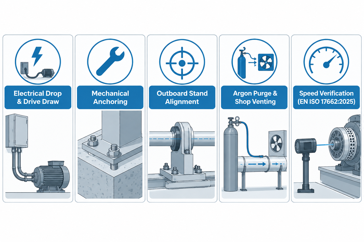
Commissioning a pipe welding turntable on the shop floor covers matching 110V/220V single-phase or 220V/380V three-phase power drops, anchoring tilting bases, and venting continuous argon purge gas. Where applicable welding codes or shop quality plans require equipment verification, technicians check travel speed with a stopwatch and a tape measure or steel rule under standards such as EN ISO 17662:2025.
Quality managers auditing WPS travel speeds in October 2026 should reference ISO 17662:2025 (adopted as EN ISO 17662:2025) for in-service welding equipment calibration and verification. The official ISO 17662:2016 lifecycle record confirms the second edition was withdrawn in September 2025 and replaced by ISO 17662:2025. The CEN EN ISO 17662:2025 catalog preview lists March 2026 for conflicting national standard withdrawal and restricts scope to production and site fabrication equipment. Where verification is required, the standard sets a once-a-year default, and a proven record of repeatability can reduce that frequency. Re-verify immediately after mechanical overload or drive repair.
During commissioning, faceplate rotational speed should be measured with a calibrated tachometer against the WPS setpoints, minimum and mid range. Where continuous argon back-purging is used, shop floor exhaust should be used. Never vent argon into below-grade pits or confined spaces where heavier-than-air inert gas displaces breathable oxygen.
| Commissioning Domain | Benchtop Models (BY-50 to BY-300) | Floor-Mount Models (BY-500 to BY-2000) | Acceptance Check |
|---|---|---|---|
| Electrical Drop & Drive Draw | 110V or 220V 1-phase, 50/60 Hz (25 to 60 W motor) | 220V/380V 3-phase (90 to 180+ W motor) | Dedicated breaker + verified chassis PE earth |
| Mechanical Anchoring | Bolt base ears to level bench; isolate ground path | Concrete expansion anchors sized for 90° overturning moment | Zero base lift under rated static proof check |
| Outboard Stand Alignment | V-roller stand for tubes exceeding chuck cantilever limit | Laser or spirit-level axis alignment with roller stands | Zero chuck binding or axial pipe walk over 3 turns |
| Argon Purge & Shop Venting | Through-bore swivel (Ø20 to 80 mm BY range) + bench fume hood | Rotary purge manifold (Ø20 to 80 mm BY range) + local exhaust vent | Leak-free swivel; safe oxygen levels in work bay |
| Speed Verification (EN ISO 17662:2025) | Stopwatch and steel rule check across WPS setpoints when required | Loaded stopwatch and steel rule check across WPS setpoints when required | Yearly verification record unless otherwise specified, plus a recheck after repair |
Frequently Asked Questions
How does a pipe welding turntable work during circumferential TIG and MIG welding?
A pipe welding turntable grips the spool or flange with a 3-jaw chuck and rotates it around a vertical or tilted axis while the torch remains in a 1G flat or 2G horizontal position.
A copper-graphite rotary brush or slip-ring assembly returns welding current from the rotating spindle to the power supply. A shielded foot pedal starts, stops, and trims rotational speed.
Which pipe welding turntable is best for small-diameter stainless steel sanitary tubing?
Look for a benchtop turntable of 50-100 kg with a variable speed drive in the range of 0.3-5 rpm and a copper shielded 3-jaw welding chuck that fits sanitary tubing. Pair it with a hollow purge spindle (an Ø20 to 80 mm option on selected BY models, or 1-1/8 to 2 1/2 in. on U.S. bench units) for clean internal argon routing.
RF-filtered control shielding provides the best protection for high frequency starts of GTAW. The rotary ground brush should be specified to the peak amperage of welding.
Do I need a hollow through-bore spindle on a pipe welding turntable for carbon steel spools?
No, carbon steel pipe spools welded with E6010, E7018, short-circuit GMAW, or flux-cored root passes run reliably on solid-faceplate turntables because the procedure needs no internal inert-gas backing.
However, specifying a hollow center bore still lets long small-diameter pipe stubs pass straight through the 3-jaw chuck body to reduce center-of-gravity overhang torque.
Can a benchtop pipe welding turntable tilt to 90 degrees?
Some can. U.S. bench units such as the Pandjiris Mini Pro tilt from 0 to 90 degrees, but the Aubrik BY-50 through BY-500 ship as fixed 0° tables and need a custom tilt option.
How do you prevent pipe walk or axial creep when rotating long spools on a turntable with outboard stands?
Gripping a flanged datum end of the pipe spool within a 3-jaw chuck on the turntable will prevent axial walk. Also, square all V-roller stands directly to the spindle centerline.
Axial creep starts whenever passive support wheels sit skewed to the pipe barrel and pull the spool forward like a lead screw. First, adjust the turntable tilt frame to 90 degrees horizontal-axis alignment with a digital protractor. Next, level each of the outboard stands with a laser line, ensuring the free barrel imposes zero bending load on the chuck jaws. Spin the clamped pipe through three full cold revolutions before striking an arc. Check jaw runout with a dial indicator and shim any roller stand that raises the pipe wall by more than 1 mm.
What voltage and foot-pedal controls come standard on industrial pipe welding turntables?
Portable 50 to 300 kg benchtop turntables run on 110V or 220V single-phase 50/60 Hz power. Heavier 500 to 2,000 kg floor units use 220V or 380V three-phase supplies; other voltages are a bespoke build.
Standard operator control packages include hand pendants with forward/reverse selectors, stepless digital RPM potentiometers, and emergency stop buttons. Heavy-duty shielded electric foot switches handle hands-free arc starts and tie-ins. Automated pipe cells can add 24V/TTL relay handshakes or PROFINET and Modbus TCP interfaces upon request.
Request Pipe Spool Overhang Torque and Low-RPM Sizing Support
Email our engineering team your pipe outside diameter range, heaviest spool and flange weights, center-of-gravity offset, WPS speed window, and your plant’s voltage. We’ll match the right BY-Series turntable, hollow-bore chuck, or ABK pipe positioner for your shop with a 1-unit MOQ.
Editorial & Engineering Review Disclosure
Reviewed by the Wuxi ABK Machinery (Aubrik) Technical Team, an industrial welding positioning manufacturer established in 1999. Aubrik manufactures the BY-Series turntables and ABK pipe positioners referenced alongside third-party market competitors in this report. Where straight cylindrical vessels or sub-50 kg manual tacking jobs fit turning rolls or fixed V-blocks better, those boundaries are stated above. Shop engineers validate WPS travel speeds and chuck clamping forces with production test coupons, while qualified electricians verify local electrical code compliance separately.
References & Sources
- U.S. Occupational Safety and Health Administration (OSHA). 29 CFR 1910.254: Arc Welding and Cutting (General Industry Regulations). https://www.osha.gov/laws-regs/regulations/standardnumber/1910/1910.254
- European Committee for Standardization (CEN). (2025). EN ISO 17662:2025: Welding, Calibration, verification and validation of equipment used for welding, including ancillary activities. https://standards.iteh.ai/catalog/standards/cen/0da41ff8-17d1-4767-baf3-201ea728fc33/en-iso-17662-2025
- International Organization for Standardization (ISO). ISO 17662:2016 Lifecycle Status Record (Withdrawn September 2025, Replaced by ISO 17662:2025). https://www.iso.org/standard/66052.html
- European Committee for Standardization (CEN). (2009). EN 1011-1:2009: Welding, Recommendations for welding of metallic materials, Part 1: General guidance for arc welding. https://standards.iteh.ai/catalog/standards/cen/6bf05f5e-ed3a-4cbd-af32-e8ce46f0efdc/en-1011-1-2009
- World Intellectual Property Organization (WIPO) / Saudi Arabian Oil Company. (2020). Patent WO2020033478A1: Purging for Welding. https://patents.google.com/patent/WO2020033478A1/en
- MDPI Machines. (2023). ISO 9283 Performance Criteria and Related Test Methods for Pose Repeatability of Industrial Manipulators, 11(7), 734. https://www.mdpi.com/2075-1702/11/7/734
- Honhart, K. Putting the Spin on Benchtop Positioners for Tube and Pipe Welding. The Fabricator. https://www.thefabricator.com/thefabricator/article/arcwelding/putting-the-spin-on-benchtop-positioners-for-tube-and-pipe-welding
- Ladd, J. 5 Things Welders Need to Know About Weld Positioners. The Welder / The Fabricator. https://www.thefabricator.com/thewelder/article/arcwelding/5-things-welders-need-to-know-about-weld-positioners
- Burgart, D. Welcome to the World of Positioneering. The Fabricator. https://www.thefabricator.com/thefabricator/article/arcwelding/welcome-to-the-world-of-positioneering-
- Bancroft Engineering. Rotary Welding Positioners (Models TT100, TT212, TT500 Specifications & Pricing). https://bancrofteng.com/standard-welding-accessories/welding-positioner/
- Baileigh Industrial. Rotary Welding Positioners Catalog (Models WP-450, WP-750, WP-1100). https://www.baileigh.com/metalworking/welding-equipment/welding-positioners/rotary-positioners
- Surplus Record Machinery & Equipment Directory. Industrial Welding Positioners & Rotary Turntables Market Listings. https://surplusrecord.com/machinery-equipment/welding-positioners/