Get in Touch with Aubrik Company

H-Beam Assembly Welding Machine Manufacture: Match the Whole Line

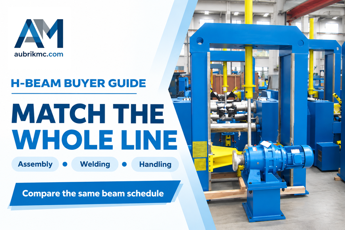
For h-beam assembly welding machine manufacture, consider the assembly station, the main welding station and the handling equipment in relation to the same beam schedule. A beam that fits the assembly frame can exceed the standard gantry’s working envelope. Start with three dimensions: Web height, flange width and the length of the beam. Then assess the weld and installed cost.
Updated October 2026
What does an H-beam assembly welding machine include?
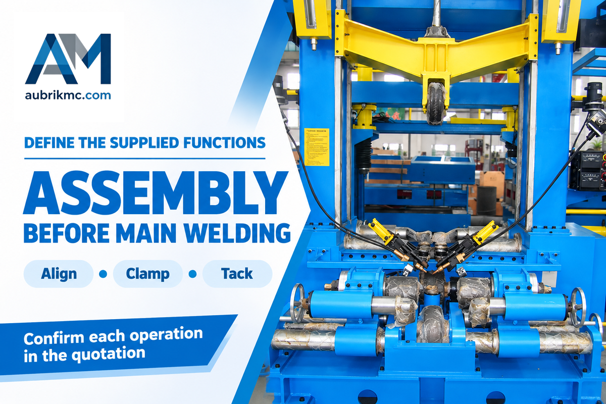
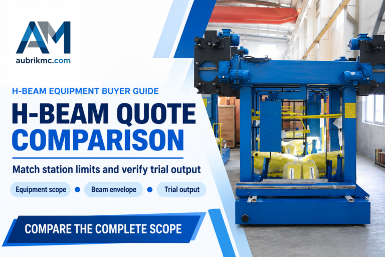
An H beam assembly machine aligns and tacks the web and flange plates; an integrated unit may combine assembly, continuous welding and straightening. The purchase specification must show which operations the quoted equipment performs, since assembling a section and completing its structural welds require different equipment and acceptance checks.
The arrangement of Aubrik’s separate stations puts assembly before the gantry submerged arc welding machine, followed by a flange straightening machine and surface preparation. Hydraulic centering and a clamp hold the workpiece during fit-up. Tack welding maintains the web plate’s position against the flange plate for transfer. Continuous longitudinal welding joins the plates to the specified weld size; H beam straightening addresses the resulting deformation.
Put those functions on the supplier’s layout drawing. A beam fabrication quotation headed “assembly welding” can otherwise leave the buyer expecting a completed beam while the seller has priced only an assembling machine with tacking equipment. For the underlying plate positioning sequence, use the assembly process and fit-up guide.
Match the assembly machine to the gantry welding station
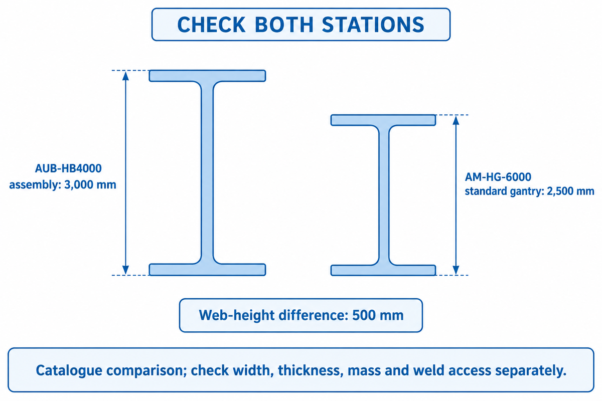
Aubrik lists a maximum web height of 3,000 mm for the AUB-HB4000 assembly unit, compared with 2,500 mm for the largest standard AM-HG-6000 gantry. The corresponding maximum flange widths are 1,500 and 800 mm. Comparing stations exposes dimensional constraints that choosing the largest assembly unit alone would miss.
| Assembly unit | Dimension | Assembly catalogue | Largest standard gantry: AM-HG-6000 | Buying implication |
|---|---|---|---|---|
| AUB-HB2000 | Web height | 200–1,800 mm | 200–2,500 mm | No upper-height conflict in these listings. |
| AUB-HB3000 | Web height | 300–2,500 mm | 200–2,500 mm | Upper heights coincide; other limits remain. |
| AUB-HB4000 | Web height | 400–3,000 mm | 200–2,500 mm | Top 500 mm requires a different welding envelope. |
| AUB-HB2000 | Flange width | 200–800 mm | 200–800 mm | Width ranges coincide. |
| AUB-HB3000 | Flange width | 250–1,200 mm | 200–800 mm | Widths above 800 mm need another arrangement. |
| AUB-HB4000 | Flange width | 300–1,500 mm | 200–800 mm | The upper-width difference is 700 mm. |
| AUB-HB2000 | Beam length | 4,000–15,000 mm | 2,000–18,000 mm | Compare roller support and loading separately. |
| AUB-HB3000 | Beam length | 5,000–20,000 mm | 2,000–18,000 mm | The top 2,000 mm exceeds the standard listing. |
| AUB-HB4000 | Beam length | 6,000–25,000 mm | 2,000–18,000 mm | The upper-length difference is 7,000 mm. |
Source: Aubrik’s published assembly and gantry specification tables, reviewed October 2026. Each row of the tables compares a given dimension and a job-specific specification is required to define simultaneous maximum dimensions and an approved station pairing. Listed custom dimensions for gantry units are separate from the standard units.
According to the AUB-HB assembly specifications, web thickness and flange thickness are shown separately. An accepted flange width doesn’t imply the machine can handle the proposed plate thickness or the mass of the beam, particularly when a heavy fabrication job requires the handling machine to support the complete section during transfer.
Will my largest beam fit both the assembly and welding machines?
The limiting dimensions and loads for both stations must leave access for the welding heads and supporting rollers. Compare the actual section diagram for each station. Height alone leaves flange reach and plate thickness, length and handling unresolved.
Consider an assumed beam with a 1,800 mm web, 700 mm flanges and a 12,000 mm length. Its three dimensions fall within the AUB-HB2000 listings, but the web exceeds the AM-HG-4000’s 1,500 mm limit. The AM-HG-5000, listed for webs up to 2,000 mm, becomes a dimensional candidate. The production engineer still needs to resolve plate thickness, beam weight, torch access and the specified joint before selecting that combination. If the exceptional job instead has a 2,800 mm web, moving to the larger assembly frame would leave a standard-gantry constraint. Specify the custom welding arrangement with that job, rather than expecting an assembly upgrade to extend the whole line.
Use the AM-HG gantry welding machine specifications and the assembly drawing to select the stations. Welding gun access to the beam flange must also be shown on the section sketch.
How much beam output can the line actually deliver?
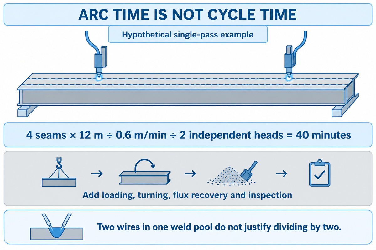
H-beam calculations include travel time, loading, fit-up, turning, correction, and inspection time, as well as beam travel speed (Assembly feed speed) and the speed of travel along a seam (welding speed). Neither, individually, gives an acceptable number of beams produced per shift, especially with several weld passes or shared control of handling equipment.
In Subarc for structurals, ESAB contributor Sean Moran explains how material handling and positioning affect arc-on time. A request for a timed sequence from the loading of the plates to the inspected member would give a better picture of the constraints.
How long do four longitudinal seams take to weld?
Four 12 m seams require 48 m of travel for a single pass along each seam. At an assumed 0.6 m/min, the work totals 80 torch-minutes. Two independent seam heads welding simultaneously would reduce the elapsed arc time to 40 minutes under those assumptions.
Imagine a production planner comparing that 40-minute result with a promised hourly output. The calculation is 4 × 12 ÷ 0.6 ÷ 2 = 40 minutes, before turning the beam, moving the welding trolley, recovering flux or inspecting the joint. If both wires feed one tandem weld pool, they are not two independent seam heads and the division by two does not follow. Travel time, and all other constraints, must be taken into consideration when performing this type of analysis. In addition, the real arc on time must be recorded and analyzed along with all other constraints, on the same trial beam. The whole exercise is meant to test the quote and develop an accurate production schedule.
For finance, use accepted beams as the denominator when comparing labor and consumables. Rework that occupies the gantry consumes available capacity even when its welding seam travel speed remains unchanged. Measure production efficiency across the full route. Faster trolley movement between welds helps only when that movement constrains the repeating cycle, while a longer queue at the turner can leave the welding equipment waiting despite an improved travel setting.
When do separate stations beat a 3-in-1 machine?
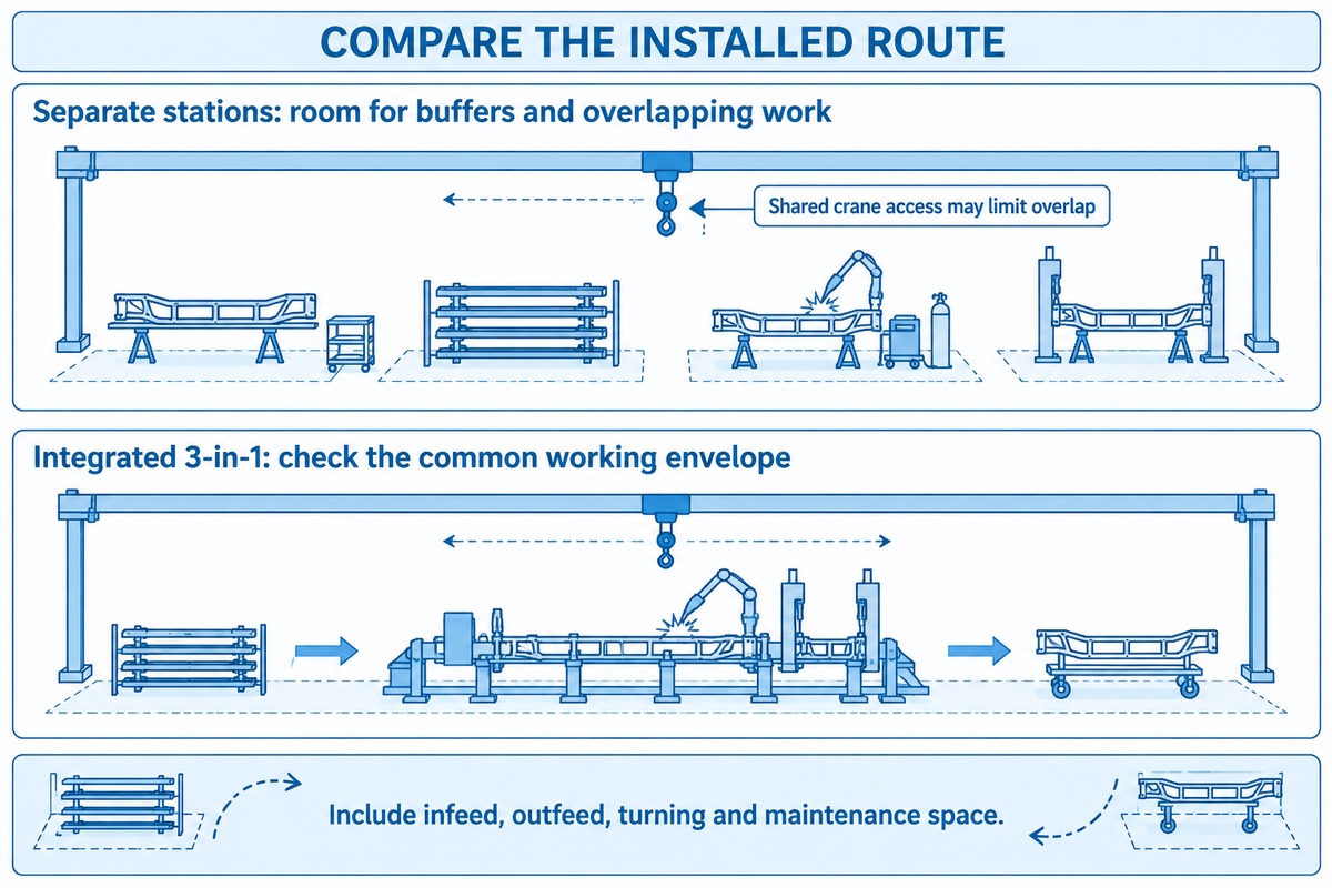
Assembly, welding and straightening stations can suit a beam mix that benefits from buffers, independent adjustments and overlapping work. An integrated welding straightening machine can suit repeated sections and a compact work area when its combined working envelope covers the jobs. Compare both automation arrangements with the same drawings, weld requirements and handling sequence.
Separate stations
- Choose for different station envelopes or changing beam families.
- Allow space for buffers, transfer and turning.
- Check whether shared cranes prevent overlapping work.
Integrated 3-in-1
- Choose when the common envelope covers the regular jobs.
- Compare complete loading and discharge arrangements.
- Account for changeovers and interruption of the combined unit.
Does a compact 3-in-1 machine need less floor space?
A compact 3-in-1 frame can reduce space between operations, but the installed footprint also includes beam infeed, outfeed, turning, access and maintenance areas. Analyze diagrams for the same longest member. Frame dimensions don’t represent the space required to move material through the equipment.
Suppose a fabricator makes repeated 12 m members but also accepts occasional deep, heavy sections. The integrated offer fits the repeat work, while the separate arrangement leaves room for a buffer before welding. The plant manager wants less travel; the scheduler wants the next beam assembled while a difficult joint remains at the gantry. If both layouts rely on the same overhead crane, the proposed overlap may disappear. Compare a repeat job and a deep job on each layout, including the crane route and discharge position. Choose integration when the reduced transfers survive that comparison; choose separation when independent station access solves the actual constraint.
Discuss the H-beam production line as a complete material route, including the cutting machine and correction. An automatic production line should identify every manual material transfer. Compare what operators still do within the operations described as “fully automatic”.
What changes the installed machine price in the United States?
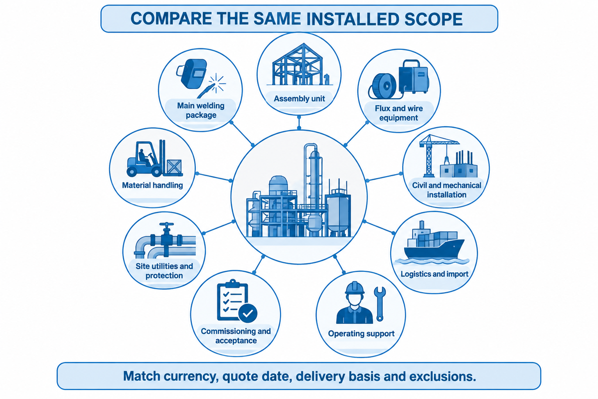
An installed price of an H-beam welding line includes more than just the main unit. Welding power sources, handling equipment, freight, foundations, electrical work and commissioning may sit in different quotations. Price comparisons for similar scopes of supply are useful; an unmatched price for the main mechanical unit leaves finance and project teams budgeting for different projects.
| Supply category | Define the included equipment or work | Allocate in the purchase scope |
|---|---|---|
| Assembly unit | Centering, clamping, tacking and controls | Supplier: identify every supplied function. |
| Main welding package | Gantry, heads, power sources and seam tracking | Supplier: list quantities and equipment ratings. |
| Flux and wire equipment | Feeding, recovery and specified storage equipment | Supplier/buyer: allocate equipment and starting consumables. |
| Material handling | Rollers, conveyors, turners and crane interfaces | Layout owner: define lengths, loads and transfers. |
| Civil and mechanical installation | Foundations, rails, alignment and anchoring | Site contractor: price the supplier’s installation drawings. |
| Site utilities and protection | Electrical connection, ventilation and guarding interfaces | Buyer/site specialists: resolve the installation design. |
| Logistics and import | Packing, freight, entry, unloading and inland delivery | Buyer/seller: state the Incoterm, named place and exclusions. |
| Commissioning and acceptance | Travel, installation support, trials and training | Both parties: assign people, duration and test jobs. |
| Operating support | Wear parts, spare components and troubleshooting | Buyer/supplier: price the starter list and support terms. |
Scope categories are another procurement comparison method. The Fabricator’s process guide explains equipment and positioning options; US Customs and Border Protection (CBP) supplies the reference for the import process. Assign the work specifically rather than generally assuming a standard seller obligation.
Request quotes for these categories and compare the same currency, quote date, delivery basis and acceptance scope. Have the relevant import charges assessed for the actual shipment; a generic machinery duty percentage would conceal classification and origin differences. CBP’s basic importing and exporting guidance details shared compliance.
Which supplier should own installation and service?
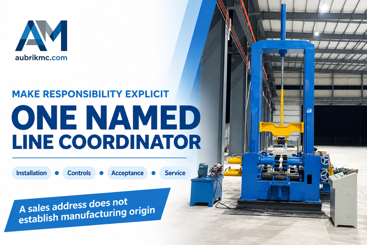
One named coordinator should integrate the assembly unit, welding package and site interfaces, while the purchase scope assigns each supplier’s work. Separate capabilities include manufacturing in the US, field service in the US and sales in the US. When deciding between assembly machine manufacturers and distributors, steel structure manufacturers should compare these separately.
Name those who align the rails, commission the control system, furnish drawings and address a failed acceptance test. Identify the responding company, the covered equipment and the spare-parts route for a given service. Making built-up H-beams from plate is a different job from welding attachments onto a rolled section, so a steel structure fabrication buyer should establish the process scope and compare offers for equipment that performs different jobs before using the existing guide to compare H-beam line suppliers.
Keep weld qualification separate from machine acceptance
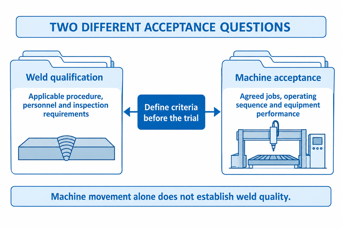
Equipment acceptance demonstrates that the delivered equipment performs the agreed jobs. Weld acceptance demonstrates that the joints meet the applicable requirements of the project. Identify the code and edition, welding process, personnel requirements, and inspection criteria, and include them with the machine trial. Joint inspection addresses a different requirement from machine positioning or quality-system certification.
AWS lists D1.1/D1.1M:2025-AMD1 for structural steel welding. Select the governing requirements from the jurisdiction, the building code and the project documents. Purchasing a new machine does not automatically change the code edition governing an existing project.
Fit-up is included in the scope of the trial because changes in gaps alter the volume of weld and affect the response to distortion. It’s illustrated in TWI’s fillet weld design guide that an increase in throat size from 5 to 6 mm increases the deposited area by about 45%. It isn’t a 45% increase in the entire line’s cost or cycle time.
For the submerged arc process, “the joint might open up if not adequately tacked.”
A trial record needs to be agreed to. Agree a trial record containing the section drawing, material, fit-up, weld size, process settings, elapsed sequence and inspection results. Define the dimensional and weld acceptance criteria before the trial. In SAW welding, record the welding flux and wire combination with the applicable welding procedure so the quality team can verify the demonstrated welding technology with respect to the joint rather than judging equipment performance from machine movement alone. This is a proposed purchase record, not a standard qualification protocol.
Specify utilities for a steel structure production line
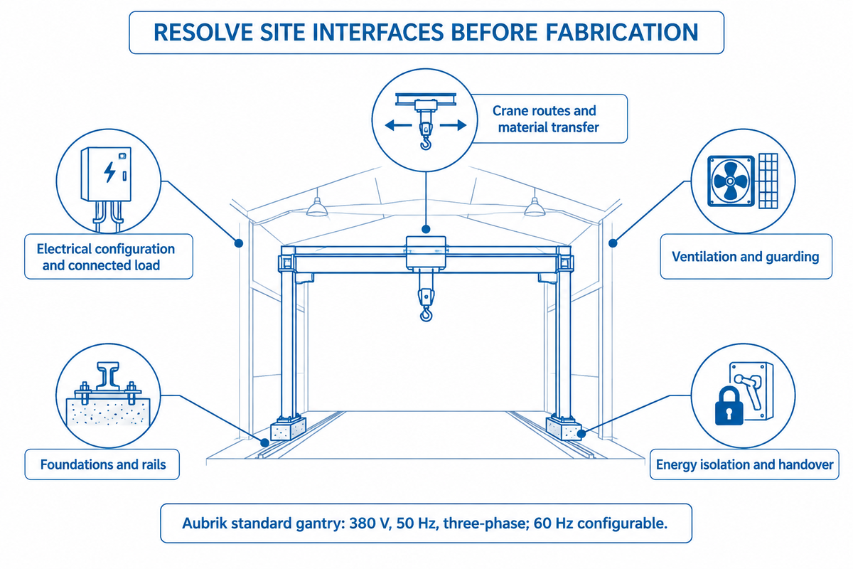
A steel structure production line requires an installation design for electrical supply, foundations, rails, ventilation, and guarding and the movement of steel. Provide site conditions with the beam schedule so the supplier can ascertain interfaces before fabrication. For US installations, nameplate voltage alone leaves equipment approval, circuit requirements and connection work unresolved.
Aubrik lists 380 V, 50 Hz, three-phase supply for the standard gantry, with 60 Hz configurable. A 480 V site therefore needs an expressly specified electrical configuration. The complete connected load schedule for this gantry type must account for the SAW power sources as well as motion and auxiliary equipment; a movement power entry describes only part of the electrical demand that the site installation design has to accommodate.
US workplace provisions address electrical equipment and installation, machine guarding and applicable anchoring, and welding fire protection and ventilation. For servicing covered by OSHA’s hazardous-energy control rule, coordinate site and outside personnel’s procedures. Include electrical, hydraulic and stored-energy isolation information in the handover.
Selecting a machine for steel structure production starts with the actual factory job range. Copy the following parameters in your request for quotation (RFQ), including the smallest regular section and exceptional jobs. Identify if the upstream CNC cutting system uses gas cutting or plasma cutting and provide sizes of the plates it cuts. Specify required pneumatic connections if the auxiliary equipment quoted uses compressed air. CNC data transfer and mechanical transfer are two other integration questions for the steel fabrication layout. If H-beam and T-beam jobs share the workshop, identify both on the layout and the quoting company will consider how they should be treated separately.
| Parameter | Recommended range | Why it matters | How to verify |
|---|---|---|---|
| Section envelope | Actual minimum/maximum height, width and thickness, mm | Sets cross-station fit. | Compare approved section drawings. |
| Length and mass | Regular and exceptional jobs, m and kg | Sets support and handling loads. | Check the loaded layout and rated capacities. |
| Joint specification | Specified weld sizes, mm; material grades | Sets passes and process requirements. | Use drawings and the applicable procedure. |
| Output target | Required accepted beams per shift; shift hours | Defines the production task. | Time the complete trial sequence. |
| Site electricity | Measured supply, V/Hz/phases; available capacity | Defines the electrical configuration. | Review supplier data with the site electrical specialist. |
| Workshop layout | Available length/width and crane clearances, m | Reveals transfer and access constraints. | Review a dimensioned installed layout. |
| Acceptance scope | Agreed trial jobs and measured tolerances, mm | Connects purchase scope to usable output. | Agree criteria and inspection records before shipment. |
- Send three job drawings — smallest regular, largest frequent and exceptional members.
- Resolve the station constraints — confirm dimensions, loading and weld access across the route.
- Agree the installed scope — assign utilities, handling, commissioning and support.
- Set the trial record — compare accepted output, labor and rework against the same jobs.
To discuss a beam schedule with Aubrik, send those drawings and the site layout. The next important decision is whether the quoted stations cover the actual work mix within the factory’s handling and utility constraints.
Frequently Asked Questions
How are the web and flange plates held during automatic assembly?
An automatic H-beam assembly station uses positioning and clamping equipment to align the web and flange plates before tacking.
Hydraulic centering brings the plates into the required relationship, while the clamp maintains contact during fit-up. Tacks then hold the assembled section for the next operation. Specify the plate sizes and joint arrangement with the supplier, because the clamping range and welding access must suit the actual section. Assembly tacks are distinct from completing the longitudinal structural welds.
How is a horizontal H-beam line arranged?
A horizontal H-beam line arranges assembly, welding, turning and transfer around the required member orientation.
The layout must show how plates enter, how the assembled member reaches each welding position and how the completed beam leaves for correction or inspection. Roller lengths, turner capacity and crane routes are part of that arrangement. Ask for a drawing covering the complete material path; the label “horizontal” alone doesn’t establish which transfers are automatic or how many handling operations remain.
Can I buy an H-beam welding machine manufactured in the USA?
US manufacture is a supplier-specific purchasing requirement that must be established for the quoted H-beam equipment.
Request the legal manufacturer’s name and factory location for the mechanical unit, then identify the origin of the welding power sources and controls separately. A US distributor or service address doesn’t establish where the machine was manufactured. If domestic field support is the priority, specify the responding service organization and covered work directly rather than treating manufacturing origin as a service guarantee.
Is feed speed enough to predict beams per shift?
Feed speed alone cannot predict accepted beams per shift.
Loading, joint preparation, weld passes, turning and inspection consume time beyond movement through the assembly station. Compare complete trials using the same beam and acceptance requirements.
What should I send for a comparable machine quotation?
A comparable H-beam machine quotation starts with drawings, the beam mix, weld requirements, an output target and site conditions.
Include the smallest regular member, the largest frequent member and the exceptional section, with web and flange thicknesses, lengths, materials and weights. State which welds the line must complete and the inspection criteria that define an acceptable beam. Provide available electrical supply, workshop dimensions, crane access and the upstream cutting arrangement.
Ask every bidder to return the same scope breakdown: assembly, main welding, correction, handling, flux equipment, utilities, freight, installation, commissioning and initial support. Identify exclusions and the party responsible for each interface. Where a bidder offers a custom envelope, have that configuration shown on the proposed layout and linked to the trial jobs. This lets procurement compare equipment and project cost while production checks the route through the factory.
References & Sources
- The Fabricator: Subarc for structurals Sean Moran, ESAB; handling and welding productivity.
- The Fabricator: Is submerged arc welding the right process for you? Robert Fox, Hobart Brothers; equipment and positioning.
- Basic Importing and Exporting US Customs and Border Protection.
- D1.1 structural welding code information American Welding Society.
- Fillet-weld design guidance TWI.
- Distortion control: prevention by fabrication techniques TWI.
- Distortion: types and causes TWI; fit-up, shrinkage and restraint.
- 29 CFR 1910.303: electrical requirements Occupational Safety and Health Administration.
- 29 CFR 1910.212: machine requirements Occupational Safety and Health Administration.
- 29 CFR 1910.252: welding requirements Occupational Safety and Health Administration.
- 29 CFR 1910.147: control of hazardous energy Occupational Safety and Health Administration.