Get in Touch with Aubrik Company

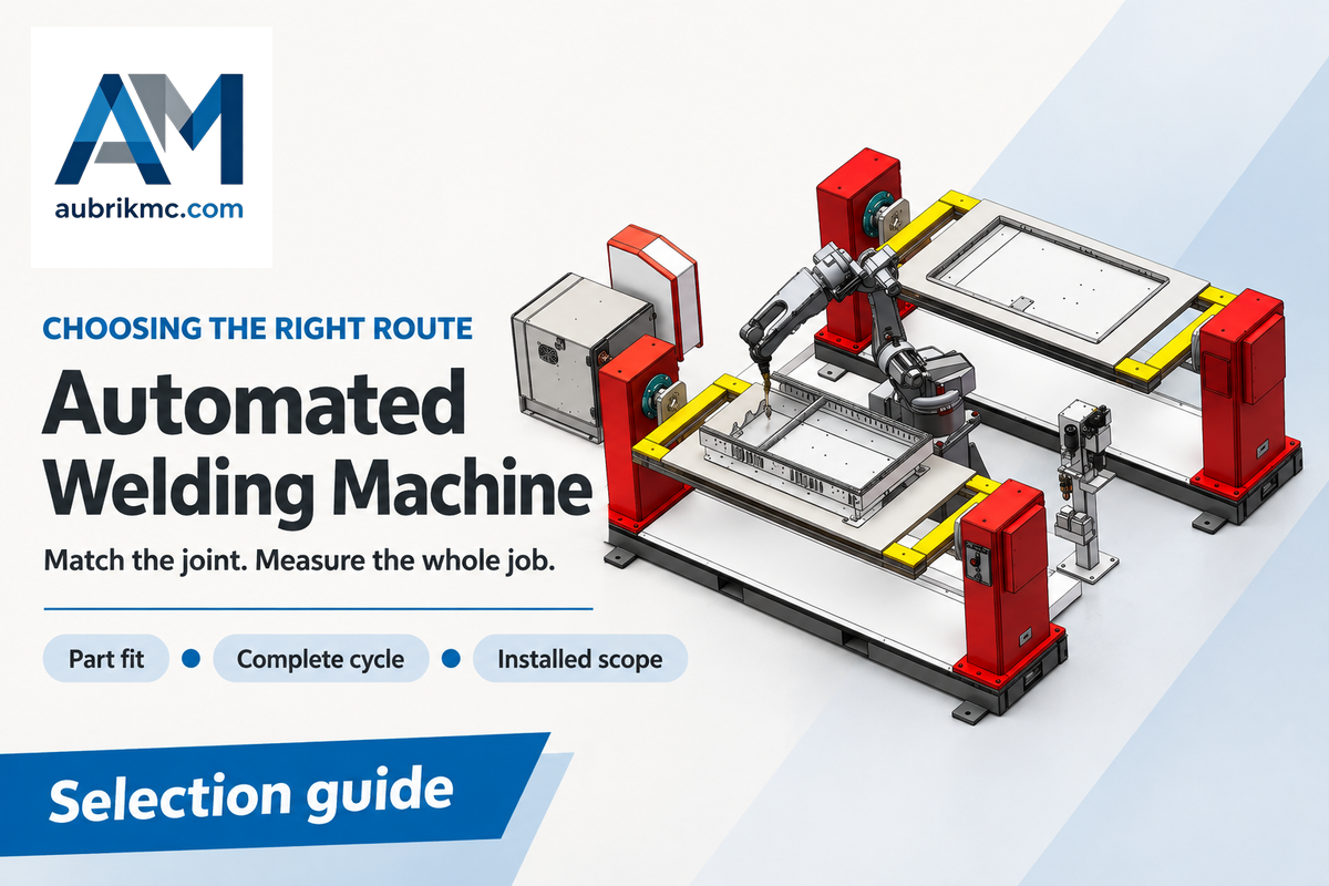
If the movement, workholding and welding process for your components match those implemented by a welding machine, it’s worth evaluating. However, look at repeatability and joint geometry first, followed by accepted parts per shift and the complete installed cost. Faster torches alone won’t improve fitting, loading or inspection throughput.
By Aubrik · Updated October 2026
A circumferential seam on a pipe, a frame with welds on multiple faces and a straight beam seam require different types of motion. The guide connects joint differences to a choice of equipment and a complete-cycle calculation. What a supplier should include in a quotation is also outlined. This guide is written for fabrication shops evaluating dedicated machines, industrial robots and cobots.
Automated welding machines: what the term includes
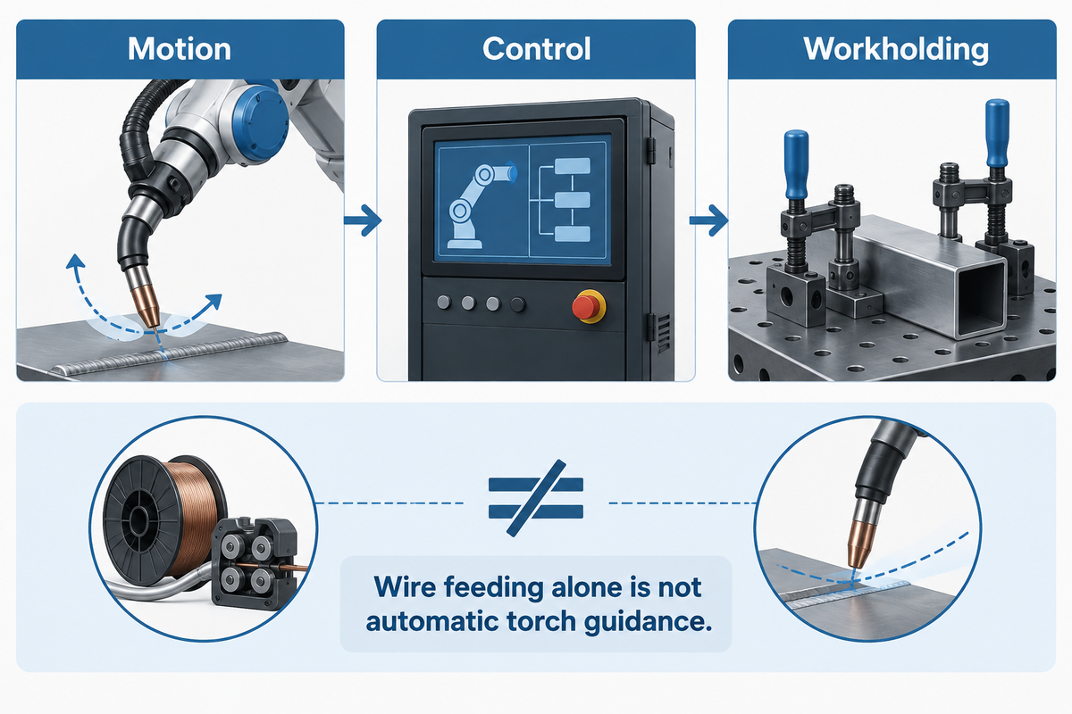
Automated welding machines perform welding tasks by moving the workpiece or the torch, or both, and controlling the process during welding. Loading parts by hand doesn’t, by itself, make a welding method semiautomatic.
What is the difference between machine welding and automatic welding?
Machine welding covers different kinds of equipment. Automatic welding describes the method of control for welding operations. TWI’s terminology explains that mechanized welding means that operators can manually set parameters during a welding operation. In automatic welding, the parameters are set and adjustments are done between operations. Robotic welding is an example of automatic welding.
A hand-guided MIG welder illustrates the difference. Its wire feeder advances the electrode, but manual welding requires the human operator to guide the welding torch. Automatic wire feeding alone isn’t the same as automatic torch guidance. Conversely, an operator can load a fixture and start a machine-controlled weld without guiding that weld by hand.
Equipment choices include robotic arms and dedicated motion systems; to automate the welding process, both need more than a power source. Motion, control and workholding have to function together. Aubrik’s robotic welding systems are one branch of this wider equipment family; dedicated linear or rotary machines serve other joints.
Fixed automation, robot welding and cobot welding
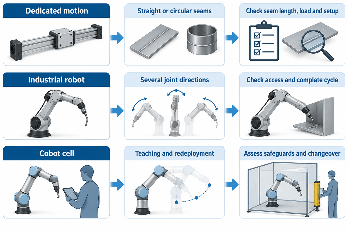
Fixed automation fits a stable motion path; robot welding fits parts that need reprogrammable access to multiple joints. Cobot welding can simplify teaching and redeployment, but still requires proper fixturing and safeguarding. The benefits of welding automation depend on the part family, set-up workload and production schedule. Choose the type of automation from those requirements and then compare arm brands.
| Approach | Useful part pattern | What to measure first |
|---|---|---|
| Dedicated linear or rotary motion | Repeated straight or circumferential seams | Seam length in mm; rotating load and fixture mass in kg; setup time in min |
| Industrial robot cell | Frames and assemblies with several accessible joint directions | Torch access, fixture envelope in mm, complete cycle in min |
| Cobot welding cell | Part families where teaching and frequent redeployment matter | Teaching and changeover time in min; assessed application safeguards |
The motion distinction follows TWI’s robotic arc welding explanation; the selection questions are an engineering synthesis. The reach of a robotic arm doesn’t prove that its torch can access every joint. The fixture, cable routing and workpiece can limit that reach.
For mass production and high-volume welding, fixed automation systems can repeat a narrow task with little program change. They aren’t automatically less expensive than programmable automation: special tooling and later product changes can reverse the comparison. Equipment used in flexible automation needs reusable fixtures, accessible programs and a workable changeover.
Small batches deserve a closer look. In a 2012 report on GH Metal Solutions, recurring work supported reusable quick-change fixtures while some nonrepeating work stayed manual. Recurrence is useful, but it isn’t an absolute requirement. Carnegie Mellon’s weld-sequence project automated preparation and fixture planning for a custom spaceframe. Setup itself can be part of the automation project.
Compare cobot welding options with the effort required to create and edit welding programs, locate parts and recover from faults. Ease of teaching is important to the extent it translates into real reduction of setup work, as opposed to just the number of screens on the pendant.
Welding applications: straight seams, pipe and frames
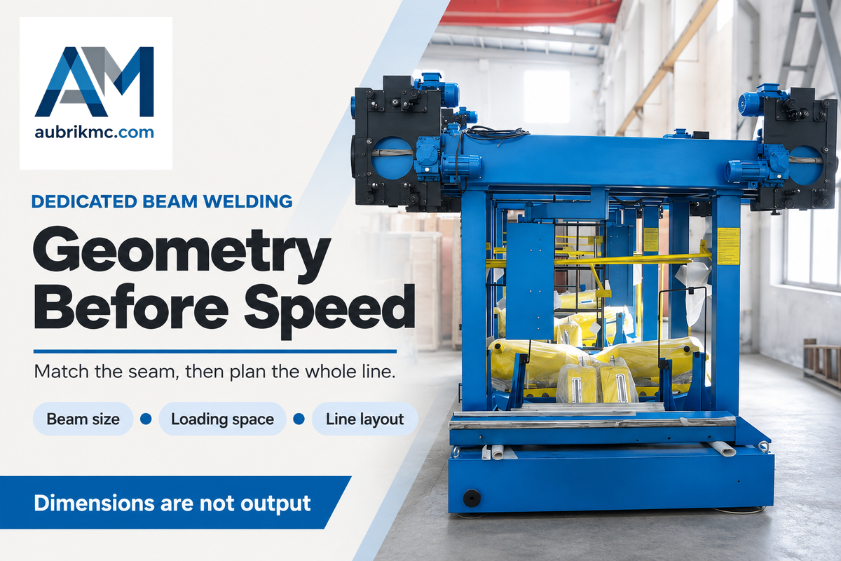
Joint geometry determines the starting point for the movement required for a workpiece to be processed. Straight seams can suit a traveling head. Circular joints can suit a rotating workpiece. A complex frame may require a robot and positioner. The welding process must then be appropriate for the material, thickness, joint design and inspection.
For long structural seams, H-beam gantry welding machines provide a dedicated travel arrangement. Aubrik’s published AM-HG4000, AM-HG5000 and AM-HG6000 model table lists beam-length maxima of 12,000 mm, 15,000 mm and 18,000 mm respectively. Those are model dimensions, not finished-beam production rates.
In the example of gantries, the published model dimensions describe dedicated H-beam equipment. First, match the seam length and the beam size. Next, determine how the work is loaded and where the complete line will fit.
| Model parameter | AM-HG4000 | AM-HG5000 | AM-HG6000 |
|---|---|---|---|
| Rail gauge | 4,000 mm | 5,000 mm | 6,000 mm |
| Web height | 200–1,500 mm | 200–2,000 mm | 200–2,500 mm |
| Flange width | 200–800 mm | 200–800 mm | 200–800 mm |
| Beam length | 2,000–12,000 mm | 2,000–15,000 mm | 2,000–18,000 mm |
| Welding travel speed | 300–600 mm/min | 300–800 mm/min | 300–900 mm/min |
| Idle travel speed | 3,000 mm/min | 3,000 mm/min | 3,000 mm/min |
| Welding current | 200–1,000 A | 200–1,000 A | 200–1,000 A |
| Wire diameter | 3.2–5.0 mm | 3.2–5.0 mm | 3.2–5.0 mm |
| Listed machine power | 10.5 kW | 10.86 kW | 11.2 kW |
Source: AM-HG public models by Aubrik, linked above. Travel is the movement of a head along a seam; it doesn’t include loading, fitting, or inspection. Listed machine power requires reconciliation with welding power sources and the complete line equipment.
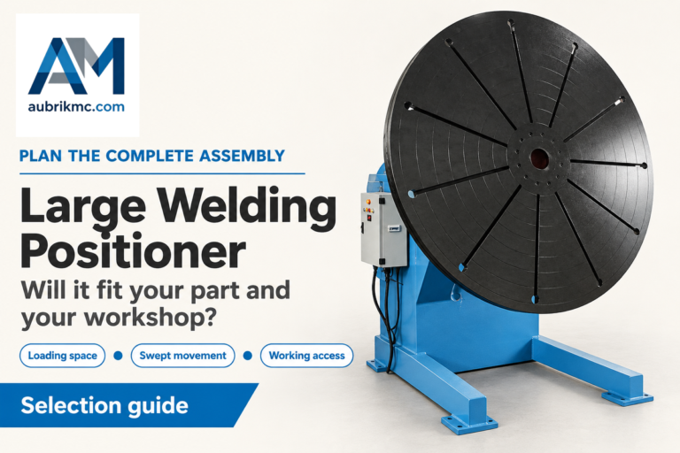
Pipe Rotators turn cylindrical work pieces, and rotary welding positioners orient a fixture and part. When determining the size of the support, include not only the masses but also the center of gravity. A turning device alone doesn’t provide the torch, process control, and workholding needed for a complete automated welding system.
Gas metal arc welding, often referred to as MIG welding in the shop, uses a continuously fed wire electrode. TIG welding uses a nonconsumable tungsten electrode and may use separate filler metal feeding. Arc welding robots can be set up for different welding processes, but changing the process changes the welding tools, supply equipment and procedure.
Resistance spot welding joins overlapping sheets at discrete locations; laser welding concentrates energy in a focused beam. Neither process is simply a faster alternative to complex welding jobs built around an arc process. Choose welding technology and type of welding first, and then select the automation technology that welding machines use to deliver the process to that joint. Modern welding tooling is designed to suit specific welding applications, not to provide a single universal torch for every material and shape.
Welding parameters, fit-up and fixture limits
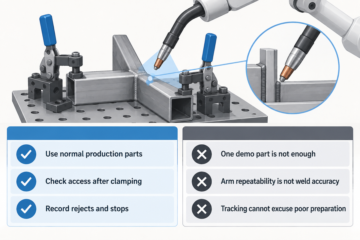
Consistent fit-up and torch access to the joint are prerequisites for repeatable automated welding. A robot follows the commanded path, but a joint that has been distorted, for example, can put the joint in the wrong location relative to that path. Sensing and guidance can adjust welding parameters within a defined application, but they can’t make every variation of a joint acceptable.
Begin with the actual drawing and welding procedure before suppliers customize the welding process. Review the part location and movement in the clamps. See if the torch can maintain the correct angle. Assess tacks, the heat build-up, and the cold, empty fixture. A tool that accurately locates the first part may not constrain the rest of the parts as welding continues.
In The Fabricator’s fixture-design article, Lincoln Electric engineer Geoff Lipnevicius connects joint access, orientation, thermal expansion and the welding circuit to fixture design. Those details explain why a fixture that works for a skilled manual welder can need changes for robotic automation. People can reposition a torch around an obstruction that a taught path doesn’t account for.
Touch sensing locates a position prior to welding, and some tracking systems can monitor changes that occur during welding. Outline which change in position the sensor needs to detect and the type of control the system can provide. Adaptive welding isn’t a substitute for the need to set welding parameters, maintain consumables and inspect the result. A stable-looking bead doesn’t guarantee acceptable internal fusion.
Do
- Use production parts with normal fit-up variation.
- Check access after clamps and tacks are in place.
- Record the cause of rejected welds and stoppages.
Don’t
- Judge the cell from a single prepared demonstration part.
- Treat arm repeatability as finished-weld accuracy.
- Use tracking to excuse uncontrolled joint preparation.
The most important question for a quality staff member is, how does the process behave for normal part variation? The most important question for a production staff member is, how quickly can a fault be identified and cleared? Both affect the consistency of the welding process. Include a worn consumable or a displaced part in the fault-recovery discussion, without requiring staff to defeat safeguards or create an unsafe weld.
Automated welding machine cost: compare complete scope
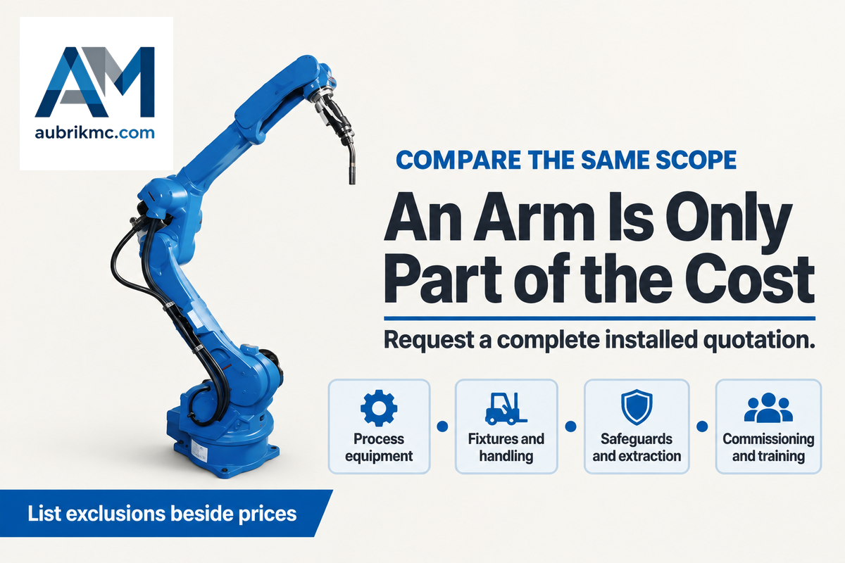
You pay more than the arm and controller for a complete welding system because process equipment, fixtures, handling, safeguarding and installation also cost money. Compare scope on this basis. Separate the initial capital cost from consumables, maintenance, support and the labor to operate the cell.
How much does a robotic welding machine cost?
A 2026 Automation World article by THG Automation CEO Matt Hendey gives $120,000 to $500,000 or more for a full robotic welding cell, including systems and integration. This range is more of a planning figure, not an Aubrik quotation. If you simply purchase an automated arm, the process equipment and integration still need to be funded. A robot-only listing and a commissioned cell describe different purchases.
There’s a similar situation with other quotes as well. An April 2026 AWS report on LeTourneau University’s training facility states that buying arms and controllers wasn’t enough to purchase a welding cell, as welding equipment, safety systems, workstations and interfaces were also needed. This provides a strong basis to compare line items before comparing totals.
For each offer, require the provider to disclose the welding power source and torch, fixtures and positioners, extraction and safeguarding, programming, commissioning, training, and site work. Freight should also be included. Provide exclusions next to each price to clarify what isn’t included in the quote. To obtain a more detailed financial breakdown, see the welding robot cost guide. This article’s next calculation will examine the production assumptions that feed this budget.
Robotic welding vs manual welding: useful output
Acceptable parts produced in the available production time determine useful output. Compared to manual welding, a robot may shorten welding while leaving preparation, loading and inspection unchanged. Subtract downtime, include normal handling, and apply the same acceptance criteria to both options before claiming a capacity gain.
Is robotic welding worth it?
Robotic welding is worth considering when the process, in its entirety, produces enough acceptable work to cover its running and installed cost. Robotic welding offers smoother motion and may release labor time. The benefits of robotic welding must still be measured through the entire process. These benefits must result in reduced paid costs, avoid the need for additional labor, or support additional work the business can sell in order to be of financial benefit to the business.
Good-Parts Cycle Test: count the whole job
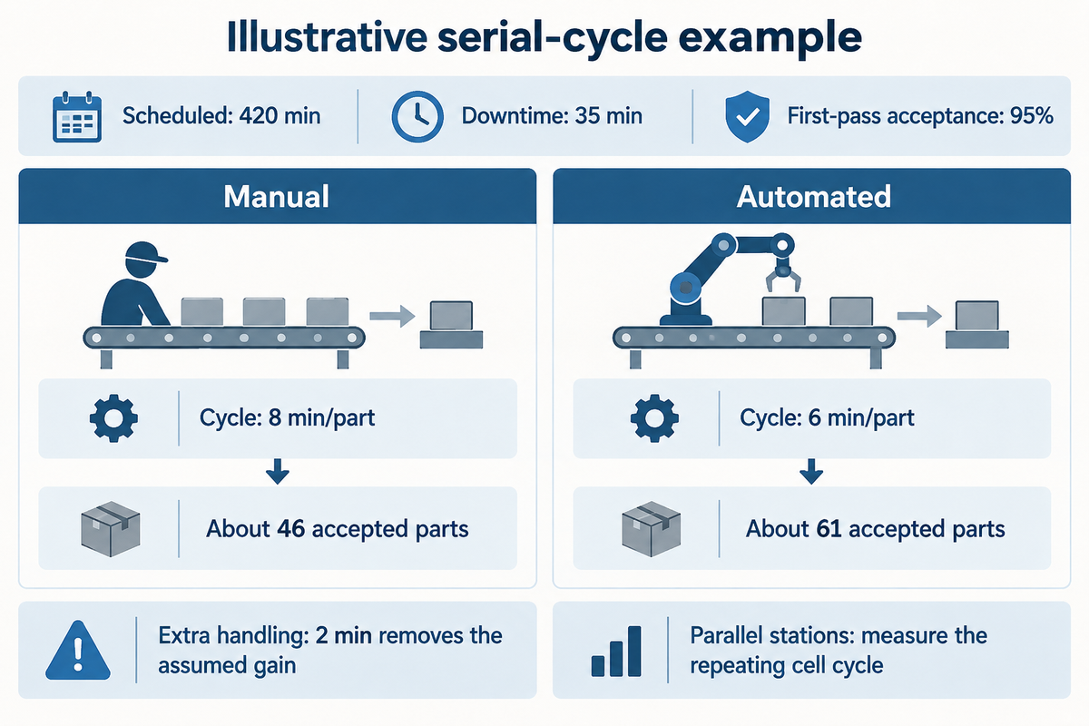
The case study provided is for illustrative purposes only, and isn’t based on measured results from a production facility. Assume the same part, procedure and inspection criteria, 420 minutes of scheduled production, 35 minutes of downtime, and a 95% first-pass acceptance rate for both methods. In this example, all steps are done in order and no loading is done during welding.
| Measured item | Manual example | Automated example |
|---|---|---|
| Prepare and fit | 2.0 min/part | 2.0 min/part |
| Load and clamp | 1.0 min/part | 1.0 min/part |
| Weld | 3.0 min/part | 1.0 min/part |
| Unload and inspect | 2.0 min/part | 2.0 min/part |
| Complete serial cycle | 8.0 min/part | 6.0 min/part |
| Scheduled production time | 420 min | 420 min |
| Downtime allowance | 35 min | 35 min |
| Net time after downtime | 385 min | 385 min |
| First-pass acceptance | 95% | 95% |
| Expected accepted output | About 46 parts | About 61 parts |
The expected accepted output is found by dividing the net production minutes by the complete cycle minutes per part, and multiplying by the first-pass acceptance rate. The manual calculation is 385 ÷ 8 × 0.95 = 45.72 and the automatic calculation is 385 ÷ 6 × 0.95 = 60.96. These are average planned outputs, and aren’t a guarantee of the actual integer output for a given day.
Now add 2 minutes of handling to the automatic station. The cycle time returns to 8 minutes, and the assumed output advantage disappears. That’s the hidden bottleneck: preparation → locating and clamping → welding → unloading and inspection. If stations run in parallel, use the measured repeating cell cycle time, instead of adding times that overlap.
A Midmark case in The Fabricator illustrates this handling distinction. In the case, separating handling from welding helps illustrate how one handling robot moved fixtures between stations, allowing loading to occur during welding. The same production was described with fewer operators, not a universal output multiplier. NIST’s 2019 robot accuracy research states degradation monitoring is critical for welding. Budget maintenance and record fault recovery rather than assuming uninterrupted motion.
This calculation helps plant managers identify lost minutes. Quality personnel determine acceptance rates. Finance personnel evaluate whether released time becomes cost savings or revenue-producing capacity. Enter measured figures into the welding payback calculator. Don’t enter every unattended welding minute as a removed payroll expense.
Welding solutions: choose the supplier and support
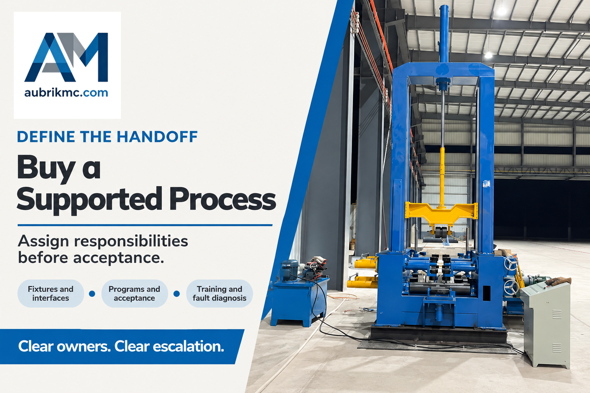
Choose the supplier of the assembled process and its support responsibilities, not only the robot badge. The arm maker, welding equipment supplier and cell integrator may be different companies. Allocate responsibility for fixtures, interfaces, programs, acceptance, training and fault diagnosis, so handoffs and fault escalation are clear.
Use the same part drawings and welding requirements for each quote. The example below works as a compact buying brief; dimensions and limits are from your actual production parts and processes rather than a hypothetical range for generic process equipment.
| Parameter | Recommended range | Why it matters | How to verify |
|---|---|---|---|
| Part envelope | Your minimum–maximum length, width and height in mm | Access and loading space | Drawings and loaded-cell layout |
| Rotating load | Part plus fixture mass in kg; center-of-gravity range in mm | Positioner load and moment | Supplier’s load and moment check |
| Joint variation | Drawing and procedure limits in mm | Locating, tracking and weld acceptance | Representative production parts |
| Output | Required accepted parts per shift and available min | Complete-cycle capacity | Timed run including handling and stops |
| Changeover | Allowed min between your scheduled part families | Production mix and setup labor | Fixture and program change trial |
| Utilities | Site voltage, Hz, available kVA and specified gas flow | Installation compatibility | Complete-cell utility schedule |
Ask who owns editable programs, who stocks consumables, and who’s responsible for a fault that spans the robot and welding power source. Send the brief with drawings when discussing an Aubrik robotic welding machine. Include the part family and production target to ensure discussions focus on the job.
Skilled welders and adaptive welding
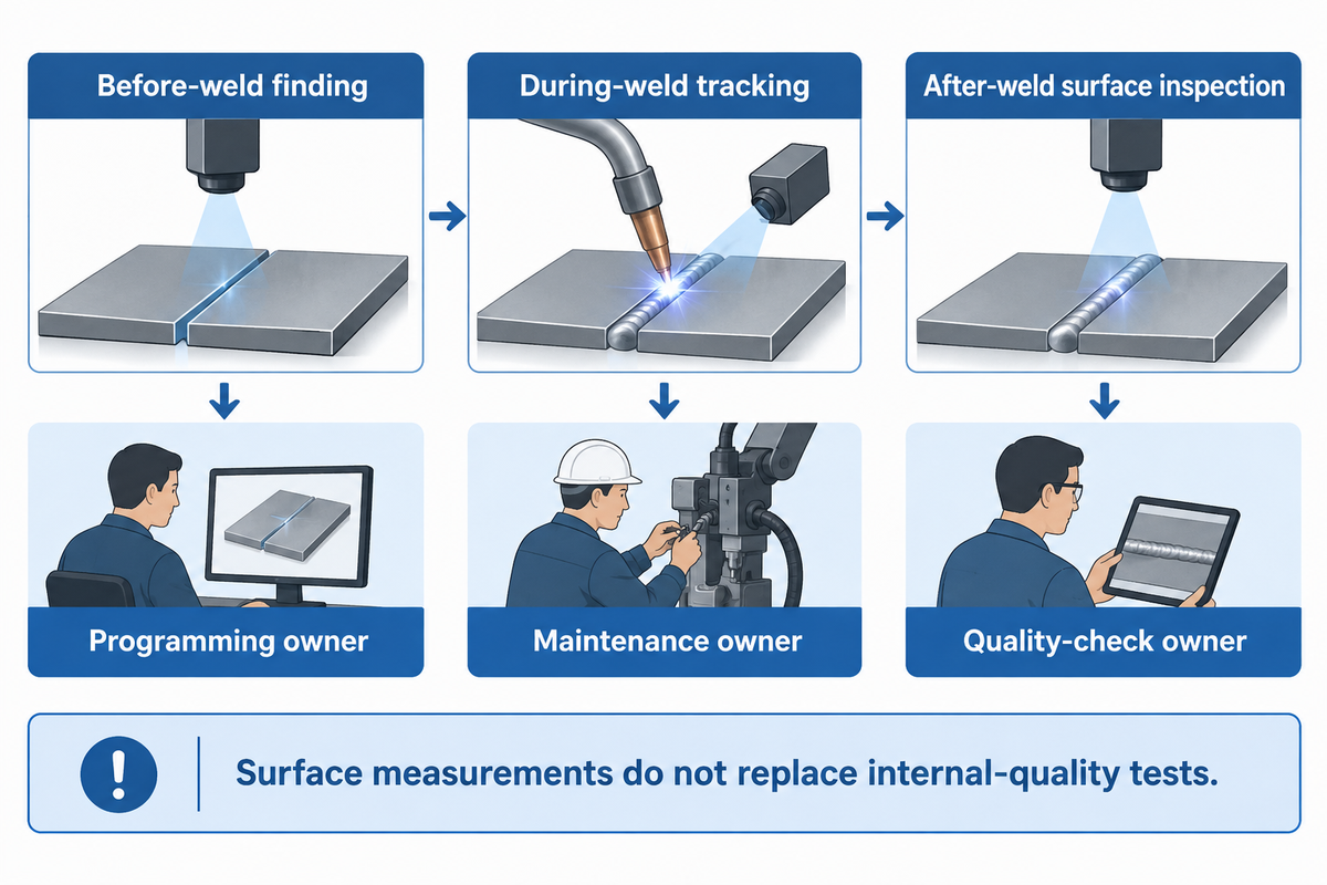
Skilled welders still establish procedures, judge joint preparation and investigate defects in an automated process. Knowledge of welding still applies in the presence of robots. Different welding tasks require clear owners for programming, maintenance and quality checks, with sensing and adaptive controls changing the response to variation during production.
Is AI replacing welders?
AI and sensing can automate welding tasks but they don’t replace every responsibility of a welder. Seam finding, path adjustment and surface inspection, for example, address specific tasks. People still establish acceptable procedures, prepare and locate parts, interpret inspection results and maintain the cell. Staffing changes are based on the entire production arrangement, not the presence of an AI feature.
Before-weld finding, during-weld tracking and after-weld surface inspection are described by Jeff Noruk, president of Servo-Robot, in an August 2026 AWS inspection article. This terminology is useful when evaluating advanced welding robots: ask exactly what’s sensed, what can change, and what inspection remains. Surface measurements, for example, don’t replace tests needed to evaluate internal weld quality.
The AWS B2.1/B2.1M:2026 standard covers qualifications for welding procedures, welders and welding operators. The public scope of AWS B2.1/B2.1M:2026 includes procedure specifications, welders and welding operators for manual through automatic welding. For welding qualifications, the requisite qualifications stated in the governing code or customer contract apply. A robot training certificate doesn’t automatically meet them.
The useful future of welding automation is task-specific; better sensing can help machines work with variation, and better planning can reduce setup. Neither justifies eliminating the need for manual inspection or skilled judgment across all welding operations. Buy a defined capability, and then make sure it’s maintained.
Welding automation systems: utilities and safeguarding
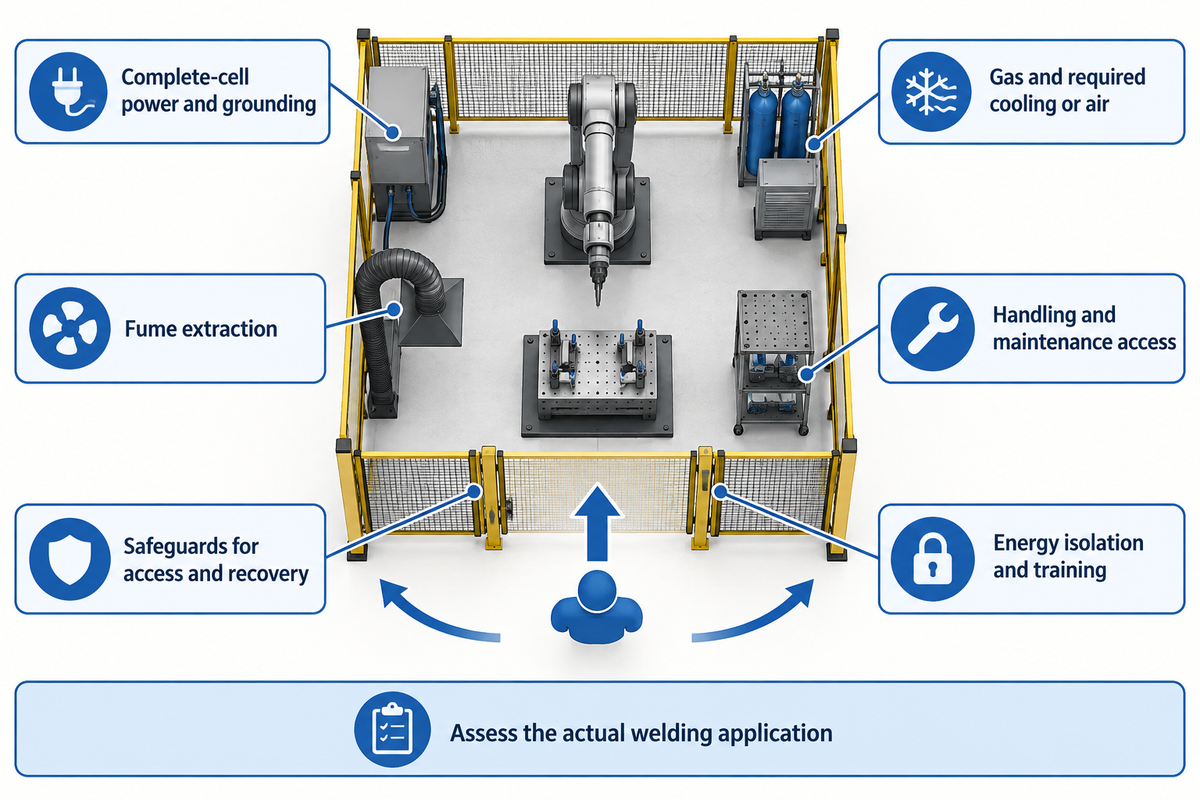
Automated welding cells require a complete installation plan for power, gas, fume extraction, access, handling and safeguarding. Size utilities for the assembled cell rather than the arm alone. Evaluate robot movement in conjunction with arc radiation, hot metal, fumes, electrical hazards and fixtures; the collaborative label doesn’t resolve the process hazards.
The 2025 editions of ISO 10218 sharpen the application distinction. A3’s update states Part 1 covers industrial robots, and Part 2 covers industrial robot applications and robot cells, replacing the 2011 editions. For a new purchase, require the integrator to identify the applicable edition and assess the actual welding application. Collaborative welding is a property of the assessed configuration, not the right to stand next to an active arc.
“The operator should be protected from all hazards during automatic operation.”
OSHA Technical Manual, Industrial Robot Systems and Industrial Robot System Safety
That includes loading and recovery, not just the normal weld path. Safeguards must address foreseeable access and maintenance tasks. Plan how operators isolate hazardous energy for servicing, and how authorized persons restore the cell after a fault. The purchase scope must include training for performing these tasks.
Fume extraction must also be included. OSHA’s Industrial Ventilation discusses source capture, hood distance, and cross drafts, which may affect control of airborne contaminants. Place extraction so contaminants aren’t drawn through the operator’s breathing zone, and consider its effect on shielding gas. Changes in the welding environment may also occur from a door or a fan.
Before installing new automation, reconcile the cell layout with crane or forklift access, fixture storage and maintenance space. Ensure supply frequency, voltage, power demand and grounding match the complete equipment schedule. Confirm gas supply and any cooling or compressed-air requirements against the complete equipment schedule. Efficient automated welding systems need parts and utilities to be available as much as they need reliable motion.
Key takeaway
Choose the machine that fits the joint, then compare the whole job: preparation, handling, welding, inspection and downtime. Complete-cell scope and accepted output make a stronger purchasing case than arm price or weld speed alone.
Frequently asked questions
Can small businesses benefit from robotic welding?
Small businesses can benefit when setup and handling leave enough useful production time.
Recurring parts can justify reusable fixtures even when each batch is modest. Start with a part family and measure loading, welding, unloading and inspection together. A cobot may simplify teaching, but inconsistent fit-up or repeated fixture rebuilding can erase that advantage. Custom work can also suit automation when preparation and setup are automated.
What are the main components of a welding automation system?
A complete system combines process equipment, controlled motion, workholding and application safeguards.
The core includes a welding power source, torch or head, controller and fixture. Process-specific additions can include wire feeding, shielding gas, cooling, sensing and part positioning. Include extraction, loading arrangements and the interfaces that let the assembled cell operate together. A list of individual machines and robots is not yet an integration scope.
What maintenance does a robotic welding station require?
Maintenance follows the equipment makers’ schedules and the welding process used.
Tasks include checking torch consumables, wire feeding, gas delivery, cables, coolant where fitted, fixtures and the robot’s specified service items. Record changes in arc behavior, positioning and part quality, rather than waiting for a stoppage. Isolate hazardous energy before servicing. Assign electrical or robot repairs to trained personnel and retain a fault history.
How do my welders work with a cobot?
Welders prepare the process and parts while the cobot performs the taught motion.
They teach or select programs, establish settings and assess results. Operators still need process knowledge and training for the application. Shared space must follow the assessed safeguards; the ability to hand-guide a stopped robot does not authorize exposure during welding.
What industries use robotic welding stations?
Robotic welding serves automotive, machinery, metal furniture and general fabrication where joints can be reached repeatably.
A welding industry label alone does not establish suitability. A frame shop may have repeatable assemblies that suit a robot, while another shop in the same sector handles variable repair work. Evaluate the part family, preparation, access, inspection and production schedule. High-speed welding offers little value if upstream fitting cannot supply parts. The relevant comparison is the complete workflow, including changeovers, staffing and the demand for accepted output, not an industry-wide productivity promise for all fabrication shops.
Can one machine automatically weld every metal and joint?
No single machine suits every material, thickness and joint.
A system may support several procedures, but changing a torch or program does not remove access or inspection constraints. Select the welding process to suit specific welding applications first, then match the motion, power source, tooling and control capability to it.
Can personnel supply parts to keep up with the demand of the automated system’s cycle time?
Personnel can keep up only when preparation and delivery match the measured cell cycle.
Measure those tasks before ordering equipment. If fitting and loading take longer than welding, a faster robot may wait more often instead of raising output. Consider fixtures, handling and upstream preparation as one system. A representative run includes normal part variation, changeovers, inspection and fault recovery. Compare accepted parts per shift with customer demand and available staffing. Full automation of the weld does not mean full automation of material movement, inspection or replenishment throughout the rest of a busy shop.
Discuss your part family with Aubrik
Bring drawings, material and thickness, joint details, part variation and required accepted output. Aubrik can help match the equipment route to the job and define the quotation scope.
Related articles
- Robotic welding systems guide — explore cell architecture in more detail.
- How to use a welding positioner — understand work orientation.
- Pipe rotator for welding guide — compare turning arrangements.
- Welding manipulator guide — review controlled torch positioning.