Get in Touch with Aubrik Company

(Last updated November 2026 · Reviewed by Aubrik Company technical team)
Quick Engineering Specifications: Beamline Steel Fabrication
- Two design routes exist for structural plants. Route A uses 3-spindle CNC drill-saw-cope lines for hot-rolled profiles. Route B uses a 5-machine cutting, assembly, gantry SAW, straightening, and blasting line for built-up H-beams (200–2,500 mm web height, 18,000 mm length).
- Three-spindle carbide drill lines process up to 125 tons per 40-hour workweek. They drill holes 30 to 50 percent faster than high-speed steel tooling while also mitering +45° to -60°.
- Twin-arc AC/DC submerged arc welding raises per-head deposition from 28 lb/hr to 55 lb/hr on 3/16-inch wire. Aubrik AM-HG gantry welders supply 63 kVA × 2 power across a 200–1,000 A current range.
- Separating the miter band saw and drill stations with material handling conveyors in between increases productivity by 30 to 35 percent.
- Pass-through 4-to-8 wheel shot blasters clean steelwork to BS EN ISO 8501-1 Sa 2.5. Fabrication quality and tolerances follow AISC 303-22, AISC 360-22 Chapter N, AWS D1.1:2025, and BS EN 1090-2 Annex B.
Beamline steel fabrication is an automated structural production workflow that coordinates conveyorized material handling with CNC machining or plate-girder welding stations. In traditional shops, wide flange profiles are moved between isolated workstations by cranes. A fully automated profile beamline connects CNC multi-spindle drilling, miter band sawing, and robotic thermal coping. Meanwhile, a heavy-duty built-up H-beam line sequences plate strip cutting, hydraulic assembly, submerged arc welding, flange straightening, and shot blasting.
According to The Fabricator’s structural fabrication equipment benchmark, a three-spindle CNC drilling system with automatic tool changers helps boost weekly output. It can process up to 125 tons of structural steel in a 40-hour work week. For heavy plate girders that are larger than standard mill sizes, engineers use hydraulic assembly machines with gantry submerged arc welders. Prospective clients that are looking to build a new bay can evaluate turnkey H-beam steel structure production line systems from Wuxi ABK Machinery (Aubrik) for custom plant layouts.
Direct Engineering Answer : The steel fabrication beamline has two main equipment flows. Flow A contains a CNC multi-spindle drilling machine, a miter band saw, and a CNC plasma cutting system for rolled profiles. Route B coordinates 5-station flame cutting, hydraulic assembly, gantry submerged arc welding, flange straightening, and shot blasting for welded H-beams. On Aubrik’s integrated H-beam line (200–2,500 mm web height), 1 to 2 operators run the full line with ±0.5 mm finished dimensional accuracy.
Key Engineering Takeaways (TL;DR)
- In capital budgeting, distinguish machine tool architectures by routes A and B. Route A machines hot-rolled profiles on advanced CNC beam drill line. Route B fabricates welded H-beams from flat steel plate across five coordinated stations.
- Splitting the miter band saw and three-spindle drill with intermediate cross-transfer conveyors boosts productivity by 30 to 35 percent.
- Structural beam webs are less rigid than solid milling tables. One Practical Machinist user reports his drill-line max. is 1,500 RPM using structural carbide inserts. Exact spindle speeds rely on drill diameter, cutting speed, and clamping stiffness.
- When welding primed plates on a gantry SAW line, even a thin weldable inorganic zinc-silicate shop primer coat can result in root wormhole porosity during high-speed double-sided welding. For this welding condition, shops must either strip primer from weld tracks or qualify welding procedures on the coated material in accordance with AWS D1.1:2025.
What Is Beamline Steel Fabrication? CNC Drill-Saw Lines vs. Built-Up H-Beam Production Lines
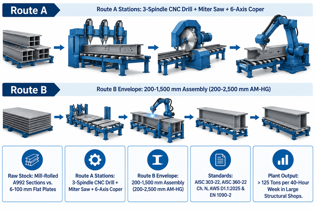
Structural beamline steel fabrication is characterized by two distinct architectures, based on the starting raw material, Route A and Route B. Route A uses a subtractive CNC drill-saw-cope beamline to machine mill-rolled wide flange sections. Route B builds up H-beams (200–2,500 mm web height) from flat steel plate using a 5-station line for cutting, hydraulic assembly, gantry submerged arc welding, flange straightening, and shot blasting.
125 Tons / Wk3-spindle CNC drill line 40-hr output
200–2,500 mmAubrik AM-HG built-up H-beam height
55 lb / hrTandem AC/DC SAW deposition per head
In the global structural steel market, plant managers across the steel industry often use the term “beamline” for two different machine lines. Confusing a structural profile drill-saw line with a built-up H-beam welding line is hazardous to plant layout. This leads to mismatched crane hook heights, undersized power transformers, and incompatible raw steel inventory. Understanding structural steel’s two primary processing routes prevents costly capital mistakes in advanced fabrication facilities.
Route A (Subtractive Profile Beamline) starts with hot-rolled structural sections delivered from a steel mill. Lincoln Electric’s structural steel fabrication application report notes that typical building frames join ASTM A992 wide flange beams to ASTM A572 Grade 50 connection plates. Shops also process I-beams, channels, structural angles, and hollow structural section (HSS) tubing. The automated beam line feeds each bar through a CNC multi-spindle drill, a horizontal miter band saw, and a robotic plasma coping cell. Together, these stations transform raw steel into connection-ready columns and rafters.
Route B (Additive Built-Up H-Beam Line) begins with heavy flat carbon or low-alloy steel plates (i.e. A36, A572 Grade 50, Q235B or Q355B, etc.). Bridges, crane runways and heavy industrial plants often require custom beam sizes, tapered webs or hybrid flange thicknesses unavailable from rolling mills. In those projects, structural steel fabricators build the girder from plate. More information on this 5-step process is available on Aubrik’s H-beam Steel Structure Production Line Systems page. The line links CNC flame strip cutting (GS-4000), hydraulic web-to-flange tack assembly (HG-1500), and double-sided gantry submerged arc welding (AM-HG). Downstream stations complete flange straightening (HYJ-40) and pass-through shot blasting (AB-SB) across workpiece lengths up to 18,000 mm.
2-Route Profile-to-Plate Line Architecture Selector
Use the 2-Route Profile-to-Plate Line Architecture Selector below to choose the proper production line for your project mix, inventory of raw stock and shop bay utilities:
| Engineering Parameter | Route A: CNC Profile Drill-Saw-Cope Line | Route B: Built-Up H-Beam Production Line | Hybrid Heavy Structural Plant (Route B + Route A) |
|---|---|---|---|
| Starting Raw Material | Mill-rolled A992 W/I/H sections, channels, angles, HSS tubing | Flat steel plates (6–100 mm cutting; 6–32 mm web; 6–40 mm flange) | Flat steel plates welded into girders, then fed into CNC drill-cope line |
| Core Machine Stations | 3-spindle CNC drill + miter band saw + 6-axis plasma coper | GS-4000 cutter + HG-1500 assembly + AM-HG gantry SAW + HYJ-40 + AB-SB | 5-station H-beam welding line + downstream CNC drill-saw-cope line |
| Section Envelope | Standard mill-rolled profile widths (Geka / Ficep / Voortman class) | 200–1,500 mm assembly web (200–2,500 mm AM-HG); 150–800 mm flange | Combined mill-rolled profiles and custom welded plate girders to 18,000 mm |
| Governing Standards & Scope | AISC 303-22 & BS EN 1090-2 tolerances; AISC 360-22 Chapter N QC/QA | AWS D1.1:2025, BS EN 1090-2 Tables B.1–B.14, BS EN ISO 13920:1997 | AISC fabricator certification concerns the shop; EN 1090 execution class follows project scope |
| Best-Fit Applications | Commercial multi-story frames, mezzanines, data centers, braced frames | Long-span PEB rafters, heavy crane girders, industrial power plants | Large structural fabricators processing more than 125 tons per 40-hour week |
CNC Beam Drill and Band Saw Lines: Multi-Spindle Drilling, Sub-Axis Milling, and Miter Cutting
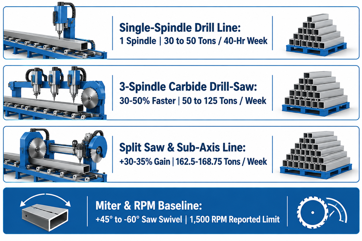
In beamline steel fabrication, a three-spindle CNC beam drill and band saw line drills both flanges and the web simultaneously while swiveling +45° to -60° for miter cuts. Indexable carbide inserts with through-spindle lubrication allow three-spindle carbide machines to run 30 to 50 percent faster than their high-speed-steel counterparts. These lines process up to 125 tons per 40-hour workweek.
When selecting a CNC beam drill line for rolled structural components, spindle configuration and clamping rigidity dictate shift tonnage. Bendmak USA’s engineering classification of beam drill lines explains that single-spindle lines rotate one head across three faces for low-volume shops. Multi-spindle systems mount three independent drilling heads: one vertical head for the web and two opposing horizontal heads for the flanges. Every hole in a connection group is drilled without flipping the beam.
On CNC drill lines equipped with a longitudinal sub-axis and milling-rated spindles, the heads can drill offset hole patterns and interpolate slotted holes while the beam stays clamped. The Fabricator’s analysis of structural steel fabrication equipment benchmarks weekly output by shop scale. During a 40-hour workweek, small fabricators process 30 to 50 tons and medium fabricators process 50 to 125 tons. Large fabricators process more than 125 tons per week. Medium-sized shops stepping into nine-spindle or three-spindle carbide drilling machines with automatic tool changers (ATC) run 30 to 50 percent faster than high-speed-steel (HSS) counterparts. They also add tapping, countersinking, chamfer prep, 4-axis layout marking, and slot milling.
Spindle speed is calculated as N = 12V / (pi * D), with cutting speed V in feet per minute and drill diameter D in inches. On Practical Machinist’s structural beam drilling technical thread, one operator reports that their structural drill line limits out at 1,500 rpm. The operator notes that structural beams are less rigid than milling-machine setups. That 1,500 rpm machine limit doesn’t establish a universal speed cap for all thin-wall structural beams. Operators set exact RPM from tooling recommendations, internal Minimum Quantity Lubrication (MQL), and hydraulic clamp stiffness. Paired inline with the drill, a horizontal mitre saw cuts at angles from +45° to -60° per Geka’s GK DSB Drill-Saw Beamline specification sheet.
How is a steel beam fabricated?
A steel beam is fabricated by CNC sawing, multi-spindle drilling, and plasma coping a mill-rolled wide flange profile, or by assembling and welding flat steel plates. In the built-up plate route, several workstations cut the web and flanges from plate and tack weld them together to form a blank. A gantry SAW fillet joins the blank faces before the assembly moves to the next station, where the flanges are straightened and shot-blasted to Sa 2.5.
| Drill-Saw Line Architecture | Spindle & ATC Configuration | Tooling & Speed Baseline | Band Saw Miter Capability | 40-Hour Workweek Benchmark |
|---|---|---|---|---|
| Single-Spindle Drill Line | 1 spindle drilling columns, base plates, and clip angles | HSS or indexable carbide; compact floor footprint | Inline or standalone horizontal band saw | 30 to 50 tons per 40-hour workweek (small fabricator benchmark) |
| 3-Spindle Carbide Drill-Saw Line | 3 independent heads (1 vertical web + 2 horizontal flange); ATC | Carbide tooling (30 to 50 percent faster than HSS); 1,500 rpm reported machine limit | +45° to -60° CNC mitre band saw (Geka GK DSB class) | 50 to 125 tons per 40-hour workweek (The Fabricator benchmark) |
| Split Saw & Multi-Spindle Sub-Axis Line | 3 or 9 spindles with ATC for tapping, countersinking, 4-axis marking, slot milling | Through-coolant MQL carbide drilling + sub-axis slot milling | Decoupled band saw with intermediate cross-transfer handling | Applying a 30 to 35 percent split saw-drill gain to 125 tons gives 162.5–168.75 tons/week |
Built-Up H-Beam Production Lines: Strip Cutting, Hydraulic Assembly, Gantry SAW, and Flange Straightening
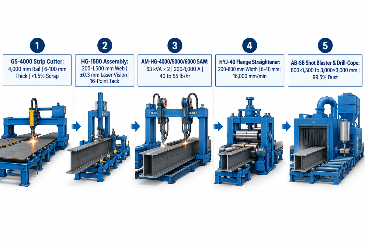
A built-up H-beam production line fabricates custom structural plate girders across five core stations. Upstream units execute CNC flame or plasma strip cutting (6–100 mm thickness) and hydraulic web-to-flange tack assembly (200–1,500 mm web). Downstream units complete double-sided gantry submerged arc welding (63 kVA × 2, 200–1,000 A), flange straightening (200–800 mm width, 6–40 mm thickness), and shot blasting.
Structural engineers often specify heavy plate girders with web heights up to 2,500 mm, variable web tapering, or hybrid flange grades. With those types of details, fabricators build beams from flat steel plate. Our engineering guide to H-beam assembly and welding machine line matching tells how to balance station capacity. High output built-up H-beam lines, in particular, subdivide the workflow into dedicated stations of the same beam envelope. Medium tonnage bays can combine assembly, welding, and straightening in a compact 3-in-1 machine while maintaining a separate strip-cutting station.
Station 1 (CNC Multi-Torch Strip Cutting, Aubrik GS-4000): The CNC flame cutting machine GS-4000 features a 4,000 mm rail spacing and an 80–3,200 mm straight-cut width. It handles a 6–100 mm flame cutting thickness while holding the cutting scrap rate under 1.5 percent. Simultaneous cutting along both strip edges can balance heat input and reduce bowing, but residual plate stress and cooling distortion can still cause long web strips to bend.
Station 2 (Hydraulic Web-Flange Assembly, Aubrik HG-1500): The hydraulic assembly machine centers the vertical web plate onto the horizontal flange plate. It uses Siemens PLC control and laser-vision positioning (±0.3 mm) with 16-point automatic spot tack welding. Per Aubrik’s H-beam production line specifications, the HG-1500 handles 200–1,500 mm web heights (6–32 mm thick) and 150–600 mm flange widths. Web-flange perpendicularity error stays under 0.3 mm/m. In addition, Patent CN103317278B (H-beam welding process) demonstrates that spaced tack welds paired with inclined temporary bracing keep adjacent plates square during final welding.
Station 3 (Gantry Submerged Arc Welding – Aubrik AM-HG-4000 / 5000 / 6000): Once tacked, the beam enters a gantry SAW station, where the main fillet welding is done. The AM-HG unit supplies 63 kVA × 2 welding power over a 200–1,000 A current range. It supports beam heights of 200–2,500 mm and lengths up to 18,000 mm with automatic flux recovery above 95 percent. As mentioned in our article, H-beam gantry submerged arc welding machine selection, a 45° beam tilt helps with boat position fillet welding. Intelligent seam tracking maintains torch alignment, while suitable current, voltage, travel speed, and torch placement help control penetration and undercut. As cited in Lincoln Electric’s structural steel welding automation productivity report, when using a tandem arrangement of submerged arc welding with alternating current and direct current, the tandem arrangement outperforms a single direct current arc. Lincoln Electric reports an ultrasonic testing weld reject rate below two percent for tandem AC/DC submerged arc welding on A572 Grade 50 structural girders.
Station 4 & 5 (Flange Straightening HYJ-40 & Shot Blasting AB-SB): After submerged arc welding, cooling fillet welds shrink and pull the flange edges inward (“mushrooming” angular distortion). Instead of slow manual flame heating, the Aubrik HYJ-40 flange straightening machine rolls 200–800 mm flanges (6–40 mm thick) at speeds up to 16,000 mm/min with ±0.3 mm rectifying precision. Actual pass count depends on initial distortion, plate thickness, and steel yield strength. The finished girder then passes through the AB-SB shot blasting machine (800×1,500 up to 3,000×3,000 mm workpiece range) for ISO 8503-1 Sa1, Sa3 cleaning. In bays that prefer fewer machine frames, an integrated 3-in-1 machine combines assembly, submerged arc welding, and flange straightening in one pass-through frame. The bay still requires infeed and outfeed conveyor space for full beam lengths.
What size welder are you using and what rough settings as this is structural work?
For shop-fabricated structural steel beams, Aubrik AM-HG gantry submerged arc welding (SAW) lines use 63 kVA × 2 power sources rated across a 200 to 1,000 A current range. Single-wire SAW deposits around 40 lb/hr at 98 to 99 percent arc efficiency. On twin-arc AC/DC tandem SAW lines using 3/16-inch (4.8 mm) wire, Lincoln Electric reports deposition rising from 28 lb/hr to 55 lb/hr. Exact amperage, voltage, and travel speed follow the qualified AWS D1.1 Welding Procedure Specification (WPS) for the joint thickness.
| Machine Category & Model | Workpiece / Section Envelope | Thickness / Joint Scope | Power / Speed / Efficiency | Primary Engineering Function |
|---|---|---|---|---|
| 1. CNC Flame Strip Cutter (Aubrik GS-4000) | 4,000 mm rail spacing; 80–3,200 mm straight-cut width | 6–100 mm flame cutting thickness (plasma optional) | Cutting scrap rate held under 1.5 percent | Slices steel plates into parallel web and flange strips |
| 2. H-Beam Assembly Machine (Aubrik HG-1500) | Web 200–1,500 mm; flange 150–600 mm | Web 6–32 mm thickness; 16-point automatic spot tacking | Siemens PLC + laser-vision positioning (±0.3 mm) | Clamps, centers, and tack-welds web to flange (<0.3 mm/m error) |
| 3. Single-Torch Gantry SAW (Aubrik AM-HG-4000) | Beam height 200–2,500 mm; length to 18,000 mm | Web-to-flange fillet welds for SME and mixed-spec batches | 63 kVA × 2 power; 200–1,000 A (~40 lb/hr single-wire SAW) | Seam-tracked submerged arc welding with >95 percent flux recovery |
| 4. Dual-Torch Gantry SAW (Aubrik AM-HG-5000) | Beam height 200–2,500 mm; length to 18,000 mm | Double-sided web-to-flange fillet welding for PEB fabricators | 63 kVA × 2 power; 200–1,000 A; 98–99 percent arc efficiency | Simultaneous dual-torch gantry SAW for mid-to-high volume shops |
| 5. Tandem-Torch Gantry SAW (Aubrik AM-HG-6000) | Beam height 200–2,500 mm; length to 18,000 mm | Heavy bridge girders and multi-pass welds with qualified WPS | 200–1,000 A (tandem SAW reaches 55 lb/hr on 3/16-in. wire) | High-deposition twin-wire tandem submerged arc welding |
| 6. Flange Straightener (Aubrik HYJ-40) | Flange width 200–800 mm | 6–40 mm flange thickness capacity | Straightening speed up to 16,000 mm/min; ±0.3 mm precision | Corrects weld-induced flange angular distortion with digital readout |
| 7. Pass-Through Shot Blaster (Aubrik AB-SB) | Workpiece range 800×1,500 up to 3,000×3,000 mm | Surface finish to ISO 8503-1 (Sa1–Sa3 cleanliness) | Abrasive recycling saves 30–40 percent; 99.5 percent dust filtration | 4-to-8 wheel centrifugal blast cleaning for coating adhesion |
| 8. 3-Spindle Carbide Drill-Saw (Geka GK DSB Class) | Rolled W/I/H beams, channels, angles, and welded girders | 3-face bolt holes, tapping, countersinking, 4-axis layout marking | Up to 125 tons per 40-hr week; +45° to -60° mitre saw | Drills holes 30 to 50 percent faster than HSS tooling |
| 9. Automated Plasma Coping Cell (6-Axis Robotic) | Structural profiles for shops of 20 to 150 people (RBTX guide) | Web copes, flange blocks, weld access holes, and 3D weld bevels | 94 percent cycle-time reduction on repeatable geometry (Tank Tech case) | Eliminates manual torch layout errors that stall downstream fit-up |
Automated Beam Coping and Thermal Profiling: 6-Axis Plasma vs. Oxy-Fuel Beveling
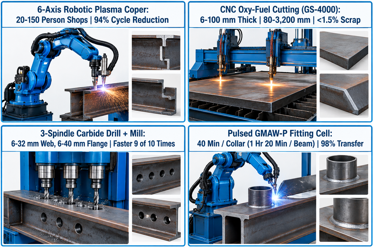
Automated beam coping cells use a 6-axis robotic plasma torch to cut web copes, flange blocks, and seismic weld access holes. The torch also creates 3D weld bevels, and oxy-fuel torches handle thick, heavy column flanges. In parts with repeatable geometry, RBTX’s automated plasma cutting guide documents a 94 percent reduction in cycle time compared to manual cutting.
Structural connections often require removing a flange block (cope), cutting seismic weld access holes (“rat holes”), or preparing V- and K-bevels for complete-joint-penetration (CJP) moment welds. Performing a notch or bevel by hand with an oxy-fuel torch and angle grinder is one of the slowest operations in metal fabrication. RBTX’s engineering analysis of automated plasma cutting bottlenecks focuses on small to mid-size shops (~20 to 150 employees). In its Tank Technology comparison, automated plasma cutting documented a 94 percent cycle time reduction on parts with repeatable geometry.
More importantly, RBTX outlines an unusual failure mode on the shop floor. Dross, bevel variation, and inconsistent hole geometry from manual or poorly calibrated plasma cutting rarely get detected at the cutting table. Instead, they move down the line and create fit-up problems and rework at the welding station. At the fit-up bay, an oversized root gap requires more weld metal to fill the joint and can increase shrinkage distortion. For the same gap error, thicker plates require even more weld metal to fill the gap.
Rolled wide flange beams have natural mill camber and sweep. To prevent bevel drift, 6-axis robotic plasma coping cells use laser vision or touch sensors. These sensors examine the actual flange and web surfaces and then ignite the arc. For round bolt holes, a group of experienced fabricators on Practical Machinist argued in favor of mechanical drilling. They said that you can drill a hole faster than you can burn a hole 9 out of 10 times, even before accounting for clean-up time. Mechanical drilling also prevents HAZ hardening around bolt holes. Once coping and drilling finish, automated welding cells attach fittings rapidly. According to Lincoln Electric, semi-automatic welding took 40 minutes for each beam collar, or 1 hour and 20 minutes per beam for two ends. The shop used pulsed GMAW-P at 98 percent metal transfer efficiency.
Why would a steel beam have a plate on the bottom?
A flat steel plate welded to a steel beam’s bottom flange increases bending strength, spreads concentrated bearing loads without web crippling, or offers a bolting seat. Engineers refer to this attachment as a flange cover plate, a bearing plate, or a bottom connection plate depending on its structural load path.
| Thermal / Mechanical Process | Primary Workpiece Scope | Bevel & Contour Capability | Cycle-Time & Edge Quality | Bolt-Hole & Joint Suitability |
|---|---|---|---|---|
| 6-Axis Robotic Plasma Coping Cell | Standard structural steel profiles in shops of 20–150 people | 3D weld bevels, web copes, seismic rat holes, HSS & sheet metal cutouts | 94 percent cycle-time reduction on repeatable geometry vs. manual cutting | Used for copes, bevels, and cutouts; thermally cut holes follow applicable code rules |
| Automated CNC Oxy-Fuel Cutting (GS-4000) | 6–100 mm flame cutting thickness across 80–3,200 mm width | Straight strip slitting and bevel prep on heavy column and bridge plates | Cutting scrap rate held under 1.5 percent; requires slag removal before fit-up | Used for plate strip cutting and thick bevels rather than finished bolt holes |
| 3-Spindle Carbide Drill + Sub-Axis Mill | Rolled profiles and welded H-beams (6–32 mm web, 6–40 mm flange) | Round bolt holes, countersinks, tapped holes, 4-axis layout marking, milled slots | Drills holes faster than burning 9 out of 10 times; 30 to 50 percent faster than HSS | Mechanically drilled bolt holes without thermal dross or a thermal cutting heat-affected zone |
Material Handling and Length Measuring: Roller-Feed vs. Gripper-Feed and Cross-Transfer Conveyors
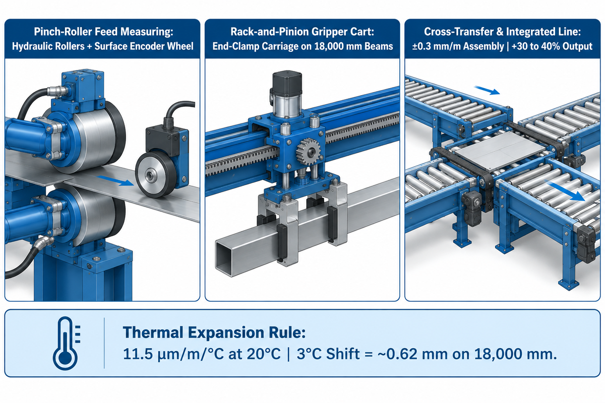
In the real world, beamline utilization is governed by material handling. Separating the band saw and CNC drill with intermediate handling systems and cross-transfer tables increases productivity by 30 to 35 percent. Aubrik reports that its integrated 5-machine H-beam line increases throughput by 30 to 40 percent compared to manual fabrication while using 1 to 2 operators and achieving ±0.5 mm accuracy.
Even the fastest three-spindle drill or twin-wire gantry welder sits idle if it waits for an overhead bridge crane to load each bar. The Fabricator highlights how conveyor buffers unlock drill capacity. Splitting the band saw and drill apart with a modest investment in material handling yields a 30 to 35 percent increase in productivity. On Aubrik’s 5-machine H-beam production line, conveyorized flow eliminates discrete crane transfers between cutting, assembly, welding, straightening, and blasting. This integration avoids fit-up misalignment, where each manual re-weld can add up to 3 hours per beam. Just 1 to 2 operators achieve 30 to 40 percent higher throughput than manual fabrication on beams up to 18,000 mm long. Engineers designing a greenfield bay can align conveyor elevations using our guide to steel structure workshop layout and crane span planning.
The second critical decision in material handling is length measuring architecture. The CNC beamlines use two competing positioning mechanisms to index long structural bars through the drill and saw:
- Pinch-roller feed measuring systems consist of hydraulic drive rollers and a measuring wheel encoder. The measuring wheel encounters slippage with heavy mill scale or wet flanges. Feed systems also require space and support for incoming beams.
- Servo rack-and-pinion gripper-feed carriages clamp the trailing end of the beam and drive along a precision helical gear rack so surface mill scale can’t cause measuring-wheel slip. Actual positioning repeatability still depends on jaw grip, drive backlash, and shop temperature. Under standard steel thermal expansion (~11.5 µm/m/°C at a 20°C reference temperature), a 3°C shop temperature shift across an 18,000 mm beam alters length by ~0.62 mm. High-accuracy lines therefore apply ambient temperature compensation.
| Handling / Measuring Subsystem | Positioning Mechanism | Accuracy & Surface Sensitivity | Conveyor & Bay Layout Requirement | Productivity & Shop Impact |
|---|---|---|---|---|
| Pinch-Roller Feed Measuring | Hydraulic drive rollers + surface encoder wheel | Sensitive to loose mill scale, oil, or ice on the beam surface | Requires full infeed roller support for the beam length (no carriage track) | Continuous pass-through feeding without carriage return pause |
| Rack-and-Pinion Gripper Cart | Hydraulic end-clamp carriage driven on helical gear rack | Eliminates surface wheel slip; requires thermal compensation on 18,000 mm beams | Requires infeed support plus carriage travel along the infeed table | Positive mechanical indexing for heavy columns and raw mill-scale stock |
| Cross-Transfer Buffer & Integrated Line | Intermediate conveyors + Siemens PLC laser-vision alignment | ±0.3 mm/m assembly accuracy and ±0.5 mm finished accuracy on Aubrik lines | Buffers intermediate bars between saw, drill, coper, and welding bays | The Fabricator reports +30 to 35 percent split saw-drill gain; Aubrik line adds +30 to 40 percent vs. manual |
BIM-to-Shop Automation: Tekla DSTV (NC1) and IFC4 Post-Processing and 4-Side Part Marking
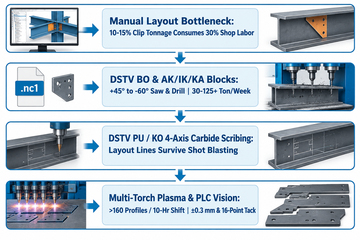
BIM-to-shop automation exports 3D structural detailing models from Tekla Structures or SDS2 directly into DSTV (.nc1) and IFC4 machine files. The Fabricator reports that a multi-torch plasma layout system can lay out more than 160 profiles in a 10-hour shift.
In traditional fabrication shops, skilled fitters spend hours with chalk lines, squares, and a center punch or hammer. According to The Fabricator, small accessory parts like clip angles and gussets typically comprise 10 to 15 percent of a fabricator’s total tonnage, yet consume up to 30 percent of shop labor hours. Modern beamlines eliminate manual layout by linking 3-D CAD detailing software (Tekla Structures, Advance Steel, or SDS2) to the machine control system via DSTV (.nc1) or IFC4 files. On Route B lines, Aubrik’s HG-1500 assembly station pairs Siemens PLC control with laser-vision positioning (±0.3 mm) and 16-point automatic spot tacking.
Within a DSTV .nc1 file, discrete ASCII blocks direct each station on the automated line. Block “ST” defines the profile header and steel grade, while “BO” specifies bolt hole coordinates and diameters. Blocks “AK” and “IK” define outer copes and internal cutouts, and “KA” programs weld-prep bevel angles. Part ID marks are stamped by “SI”, and “PU” or “KO” drives 4-axis layout marking for welded attachments. As The Fabricator notes, introducing 4-axis layout marking to a drilling system adds cycle time to the drill envelope. The Fabricator reports that multi-torch plasma marking systems can lay out more than 160 profiles in a single 10-hour shift.
| DSTV Block / Control Subsystem | Machine Axis / Tool Executed | Process Output & Survival | Downstream Fit-Up & Capacity Impact |
|---|---|---|---|
| BO & AK / IK / KA Blocks | 3-spindle CNC drill, +45° to -60° mitre saw, and plasma coper | Through-thickness bolt holes, slots, copes, and weld bevels | Eliminates manual console coordinate entry across 30–125+ ton/week shops |
| PU / KO 4-Axis Carbide Scribing | Rotary carbide scribing tool integrated on CNC drill line | Milled layout lines that remain visible after shot blasting | Marks clip and stiffener locations directly on the main member (adds drill cycle time) |
| Multi-Torch Plasma Layout & PLC Vision | Standalone plasma layout marker + Aubrik HG-1500 laser-vision PLC | >160 profiles per 10-hour shift; ±0.3 mm laser-vision assembly positioning | Offloads layout from the drill and automates 16-point spot tacking |
Surface Preparation and Weld Inspection: Pass-Through Shot Blasting, Shop Primer, and NDT
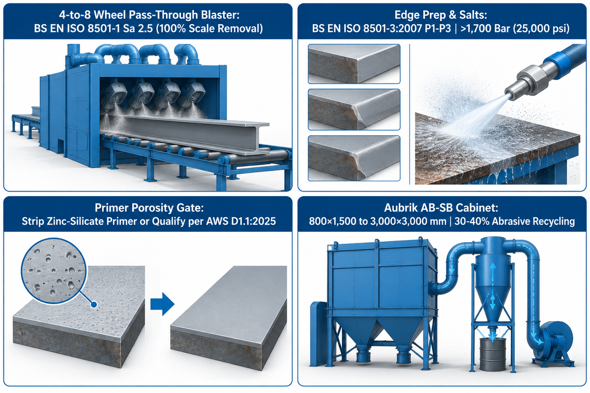
Inline pass-through roller-conveyor shot blasting machines use 4 to 8 centrifugal impeller wheels to clean structural steel beams to BS EN ISO 8501-1 Sa 2.5 (up to 100 percent mill-scale and rust removal efficiency). Separate BS EN ISO 8501-3 P1 to P3 grades govern welds, cut edges, and surface imperfections, which may require grinding before coating.
Before fillet welding, operators remove cutting dross, loose rust, loose scale, and surface contaminants. Tightly adherent mill scale can remain only when permitted by the governing welding code. Coating preparation, by contrast, requires blast cleaning to the specified cleanliness and roughness profile. The Steel Construction Institute (SCI) surface preparation engineering standard details pass-through blast plant design. Automatic blast cabinets position 4 to 8 centrifugal impeller wheels around the conveyor and can be 100 percent efficient in removing mill scale and rust. BS EN ISO 8501-1 defines abrasive blast-cleaning grades Sa 1, Sa 2, Sa 2.5, and Sa 3. Separately, BS EN ISO 8501-4 addresses high-pressure water jetting, where ultra-high-pressure water jetting above 1,700 bar (25,000 psi) removes soluble salts. Weld seams and cut edges are prepared to BS EN ISO 8501-3:2007 grades P1, P2, or P3, and surface roughness is assessed under BS EN ISO 8503-1. Aubrik’s AB-SB shot blaster handles 800×1,500 to 3,000×3,000 mm workpieces with 30 to 40 percent abrasive recycling savings. You can compare wheel blaster sizing in our guide to pass-through shot blasting vs. sandblasting for structural steel profiles.
A critical quality trap happens when shops blast raw plates and spray pre-construction weldable primer before built-up H-beam submerged arc welding. Strategic Steel’s audit of 25 structural steel fabrication problems and welding metallurgy research identify this risk. Welding over inorganic zinc-silicate shop primer vaporizes zinc in the molten pool. That trapped gas forms root wormhole porosity, especially on the second side of double-sided web-to-flange fillet welds or at high speeds in mechanized SAW. Even a thin coat of weldable shop primer doesn’t necessarily eliminate porosity. High-speed tandem SAW lines must strip primer from the web-to-flange weld track before assembly. Otherwise, the shop needs to qualify the welding procedure on coated plate per AWS D1.1:2025 Structural Welding Code – Steel. Aubrik reports 99.5% dust filtration for its AB-SB units, which use enclosed blast cabinets with cartridge dust collectors. However, inadequate capture or filter maintenance can still expose workers to levels above OSHA limits.
Are steel beams primed before delivery?
Structural steel beams are primed in the fabrication shop prior to delivery, only if directed by the project’s coating schedule. Slip-critical faying surfaces remain uncoated or are coated with a system qualified for the required slip resistance. Fireproofed steel may use a compatible primer, and field weld zones require suitable surfaces for welding. Steel to be hot-dip galvanized remains unpainted, so molten zinc can bond.
Do
- Blast structural profiles to BS EN ISO 8501-1 Sa 2.5 using a 4-to-8 wheel pass-through shot blaster, and dress weld edges to BS EN ISO 8501-3 P1–P3.
- Remove pre-construction zinc-silicate primer from high-speed double-sided SAW weld tracks or qualify the welding procedure on coated material under AWS D1.1:2025.
- Perform ultrasonic testing (UT) and magnetic particle testing (MT) at AISC 360-22 Chapter N frequencies and evaluate welds against AWS D1.1:2025 Clause 8 criteria.
Don’t
- Do not treat a thin weldable shop primer coat as an unconditional guarantee against wormhole porosity during high-speed double-sided tandem SAW.
- Do not apply unverified alkyd shop primer over slip-critical bolt faying surfaces or beams designated for spray fireproofing without confirming coating qualification.
- Do not allow thermally cut bolt holes with heavy dross or untrimmed edge defects to pass into final assembly without code compliance verification.
Dimensional Tolerances and Structural Codes: AISC 303, AWS D1.1, ASTM A6, and EN 1090 Compliance
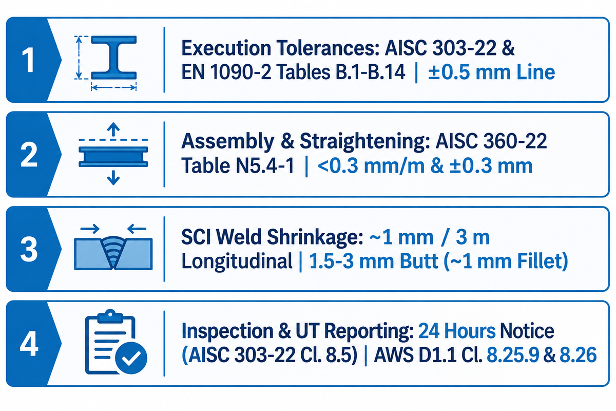
For North American structural steelwork, AISC 303-22 and AWS D1.1:2025 provide fabrication tolerances, while AISC 360-22 Chapter N addresses quality control and quality assurance. N addresses QC and QA. BS EN 1090-2 Annex B Tables B.1-B.14 provide essential and functional tolerances for manufacturing for European structural steelwork. The Steel Construction Institute estimates that weld shrinkage is approximately 1 mm per 3 m longitudinally and 1.5 to 3 mm transversely for butt welds.
A typical engineering error is assuming that raw mill tolerances as stated in ASTM A6/A6M satisfy finished erection tolerances at the jobsite. As highlighted in AWS Inspection Trends (August 2025) on AISC 360 Chapter N and AWS D1.1 inspection , quality control spans two primary codes. AWS D1.1:2025 explains how to conduct inspections and acceptance criteria for welded connections (including marking rejected UT flaws under Clause 8.25.9 and reporting under Clause 8.26). AISC 360-22 Chapter N details the required frequency of inspections in Tables N5.4-1 and N5.6-1. Also, AISC 303-22 Clause 8.5 requires the fabricator and erector to provide access and at least 24 hours’ notice for independent inspection.
For European projects, the Steel Construction Institute’s engineering guide to accuracy of steel fabrication specifies permitted deviations in BS EN 1090-2:2018 Annex B Tables B.1 through B.14. When specified, BS EN ISO 13920:1997 supplies general tolerances for welded constructions. SCI further documents that fabricators welding plate girders must anticipate thermal contraction during cutting and assembly. Longitudinal weld shrinkage is about 1 mm per 3 m of weld. Transverse contraction runs between 1.5 mm and 3 mm for single-V butt welds, and about 1 mm for double fillet welds up to three-quarters of the plate thickness.
| Quality / Dimensional Aspect | North American Code Provision (AISC / AWS) | European Standard Provision (BS EN / SCI) | Aubrik H-Beam Line & Shop Control Capability |
|---|---|---|---|
| Manufacturing & Execution Tolerances | AISC 303-22 & AWS D1.1:2025 fabrication tolerances | BS EN 1090-2:2018 Annex B Tables B.1 through B.14 (essential & functional) | ±0.5 mm finished H-beam dimensional accuracy across the 5-machine line |
| Web-Flange Assembly & Straightening | Pre-weld fit-up verification under AISC 360-22 Table N5.4-1 | BS EN 1090-2 Factory Production Control (FPC) & BS EN ISO 13920:1997 | <0.3 mm/m perpendicularity on HG-1500; ±0.3 mm rectifying precision on HYJ-40 |
| Weld Shrinkage Allowance (Estimated) | Account for thermal contraction in shop detailing and fit-up | SCI estimate: ~1 mm per 3 m longitudinal; 1.5–3 mm butt transverse (~1 mm fillet) | Program over-length shrinkage allowance into GS-4000 CNC strip cutting |
| Inspection Notice & UT Flaw Reporting | 24 hours minimum notice (AISC 303-22 Clause 8.5); AWS D1.1 Clauses 8.25.9 & 8.26 | Approved FPC inspection plan & trial erection checks where specified | Audit inspection reports, ISO 9001, and CE certificates supplied on request |
Sizing a Beamline for 500 to 1,500 Tons/Month: Cycle-Time Math, Utilities, TCO, and 2026 Industry Outlook
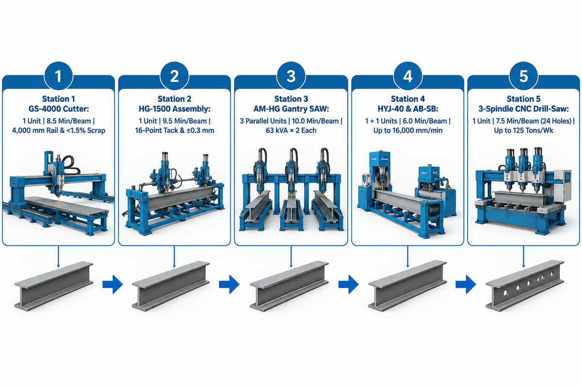
Sizing a structural steel beamline requires balancing the station cycle time for processes such as cutting, assembly, gantry SAW, straightening, and drilling instead of focusing on peak spindle speed alone. The American Welding Society projects a 360,000-welder shortage in the United States by 2027, and conventional fabrication averages 15 to 45 shop labor hours per ton. In traditional fabrication, 1 to 4 shop labor hours are expended per ton. By contrast, an integrated 5-machine Aubrik H-beam line runs with 1 to 2 operators and raises throughput by 30 to 40 percent over manual fabrication.
When plant engineers evaluate return on investment and capital budgets to reduce labor costs, the primary driver in 2026–2027 is workforce scarcity. According to AGT Robotics’ analysis of American Welding Society (AWS) workforce data, the United States faces a shortage of about 360,000 welders by 2027. The average welder is around 55 years old in the United States and over 45 in the European Union. Europe faces a shortage of over 200,000 welders by 2030, and one robotic beam welding cell can replace up to three manual welders on repetitive structural tasks. In conventional shops, SteelFlo AI’s 2026 structural fabrication cost benchmark shows that simple bolted framing takes 15 to 20 hours/ton and moderate work takes 20 to 30 hours/ton. Complex built-up welding takes 30 to 45 hours/ton. For example, a 100-ton moderate project at 25 hours/ton and a $75/hr loaded rate equals $187,500 in shop labor. Total installed structural steel costs range from $4,000 to $6,500/ton, or $2.00 to $3.25 per pound.
At the same time, emerging 2025-2026 welding innovations like JFE Steel’s “smarTABH” rationalized built-up H-beam welding method and dual-arc AC/DC tandem submerged arc welding reduce manual rework. Buyers comparing equipment quotes and utility loads can refer to our guides on how to compare H-beam making machine quotes and trial output and automated welding machine selection criteria.
5-Station H-Beam Line & Downstream Drilling Tact-Time Balancer (Illustrative Worked Example)
Balance the five Route B production stations and the downstream drilling station, as shown in the Illustrative Worked Example below, to avoid purchasing a high-speed station that starves or chokes downstream bays. Remember that Route A (rolled profile drill-saw line) and Route B (built-up H-beam plate line) have separate tact-time envelopes unless they share a finishing bay:
- Assume a target monthly output of 1,000 metric tons/month of built-up H-beams (Route B) with drilled end connections, for this sample calculation.
- Representative workpiece mix (illustrative assumption): 2,000 beams/month, with an average weight of 500 kg/beam, 12 m lengths, a 48 m fillet weld seam, and 24 bolt holes.
- Assumed effective shop time: 20,000 effective production minutes/month, over two shifts.
- Tact time required (example calculation): 20,000 effective minutes/2,000 beams = 10.0 minutes/finished 12 m beam.
| Station & Equipment Unit | Assumed Cycle Basis (12 m Beam) | Units for ≤10.0 min Tact | Balanced Tact Output | Verified Aubrik Station Rating |
|---|---|---|---|---|
| 1. CNC Flame Strip Cutter (GS-4000) | 8.5 min/beam equivalent (multi-strip batch) | 1 gantry strip cutter | 8.5 min/beam (illustrative) | 4,000 mm rail; 80–3,200 mm width; 6–100 mm thick; <1.5 percent scrap |
| 2. H-Beam Assembly (HG-1500) | 9.5 min/beam (centering + 16-point spot tack) | 1 assembly machine | 9.5 min/beam (illustrative) | Web 200–1,500 mm (6–32 mm); flange 150–600 mm; ±0.3 mm PLC laser vision |
| 3. Gantry SAW Welder (AM-HG) | At 800 mm/min assumed speed, 48 m seams = 60 seam-min (30 min for 2 simultaneous seams) | 3 dual-torch gantry welders in parallel | 10.0 min/beam arc-time basis before flip | 63 kVA × 2 per machine; 200–1,000 A; beam height 200–2,500 mm; length to 18,000 mm |
| 4. Flange Straightener (HYJ-40) & Shot Blaster (AB-SB) | 6.0 min/beam pass-through straightening & blasting | 1 straightener + 1 blaster | 6.0 min/beam (illustrative) | HYJ-40 up to 16,000 mm/min (200–800 mm flange, 6–40 mm); AB-SB to 3,000×3,000 mm |
| 5. Downstream 3-Spindle CNC Drill-Saw | 7.5 min/beam assumed (24 carbide holes + end trim) | 1 drill-saw line | At 500 kg/beam & 7.5 min cycle, theoretical output is 160 metric tons per 40 operating hours | 3-spindle ATC drill benchmark: up to 125 tons per 40-hr week (The Fabricator) |
Selecting a Beamline Equipment Manufacturer: OEM Landscape, Turnkey H-Beam Lines, and FAT Checklist
Global beamline manufacturers specialize with regard to their chosen production route. European, North American, and Turkish OEMs (Voortman, Peddinghaus, Ficep, Geka and Bendmak) focus on Route A CNC profile drill-saw cope lines. On the other hand, Wuxi ABK Machinery (Aubrik) engineers turnkey Route B 5-station built-up H-beam cutting, assembly, gantry SAW, straightening and shot-blasting lines backed by a 1-year free warranty across 80+ custom lines delivered.
When preparing a request for quotation (RFQ), buyers should match supplier core competencies to their primary steel fabrication route. Don’t force profile drill builders to quote custom plate-girder welding equipment, or vice versa:
- Route A CNC profile drill-saw and coping OEMs include Voortman (V630/V633 drill lines and V807 robotic plasma coper) and Peddinghaus (PCD drill lines and PeddiWriter). Other European and Turkish suppliers include Ficep (Valiant 3-spindle sub-axis CNC lines), Geka (GK DSB drill-saw beamlines with +45° to -60° mitre sawing), and Bendmak (B3DL multi-spindle lines). When evaluating regional distributors, such as Mac-Tech or Akyapak brochures, buyers should check spindle ratings and miter limits directly against official factory test sheets.
- For Route B turnkey built-up H-beam production, Wuxi ABK Machinery (Aubrik) H-beam steel structure production line engineers manufacture complete five-station lines. The system pairs GS-4000 CNC flame cutting machines, HG-1500 hydraulic assembly machines, and AM-HG-4000/5000/6000 gantry SAW welders with HYJ-40 flange straighteners and AB-SB pass-through shot blasters (80+ custom lines delivered). Lead time and price depend on configuration and are provided with your custom quote. Each complete system includes on-site installation, commissioning, operator training, and a 1-year free warranty with original spare parts.
Engineering RFQ & Factory Acceptance Test (FAT) Checklist for Beamline Equipment
| Verification Stage | Mandatory RFQ & FAT Inspection Inputs | Acceptance Standard / Pass Criterion |
|---|---|---|
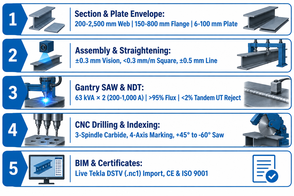
| 1. Section & Plate Envelope | Verify web height (200–1,500 mm on HG-1500; 200–2,500 mm on AM-HG), flange width (150–600 mm assembly; 200–800 mm on HYJ-40), and plate thickness (6–100 mm on GS-4000; 6–32 mm web; 6–40 mm flange) | Conduct full-load trial run across the buyer’s specified steel grades (A36, A572 Grade 50, A992, or Q355) within each station’s rated thickness range |
| 2. Assembly & Straightening | Verify HG-1500 laser-vision positioning (±0.3 mm), web-flange perpendicularity (<0.3 mm/m), and HYJ-40 rectifying precision (±0.3 mm) | ±0.5 mm finished H-beam dimensional accuracy on Aubrik integrated lines; project tolerances checked against applicable AWS D1.1 or BS EN 1090-2 tables |
| 3. Gantry SAW & NDT Quality | Verify AM-HG welding power (63 kVA × 2), current range (200–1,000 A), seam tracking, and automatic flux recovery (>95 percent) | Root fusion verified by macro-etch; UT acceptance based on AWS D1.1 weld acceptance criteria (Lincoln Electric reports <2 percent UT reject rate in tandem SAW) |
| 4. CNC Drilling & Length Indexing | Verify 3-spindle carbide hole drilling, 4-axis layout marking, and +45° to -60° mitre sawing across full beam lengths | Verify machine positioning repeatability and check hole-group and cut-length tolerances against the governing AISC 303-22 or BS EN 1090-2 project specification |
| 5. BIM Post-Processor & Certificates | Live import of buyer’s Tekla Structures DSTV (.nc1) test file (BO/AK/KA/SI/PU blocks), connected kVA load, and bay layout drawing | Zero manual coordinate edits at CNC console; CE conformity documentation for machinery and ISO 9001 certification for the supplier’s quality management system |
Pre-Purchase Verification Summary: Before signing a purchase contract, buyers should verify four site-specific conditions with their plant engineer and equipment supplier. First, verify if your monthly backlog is dominated by mill-rolled profiles (Route A) or custom welded plate girders (Route B). Second, measure unobstructed bay length under the crane hook to fit the machine frames plus full infeed and outfeed beam lengths (up to 18,000 mm on Aubrik AM-HG lines). Third, size the three-phase power supply from selected station loads and operating demand factor, since each Aubrik AM-HG gantry SAW station is rated at 63 kVA × 2. Fourth, request a factory audit, client references for H-beam lines, and ISO 9001 and CE certificates before running a Factory Acceptance Test coupon trial.
Key takeaway
Match your beamline investment to your starting steel stock. Deploy a 3-spindle carbide drill-saw-cope line with decoupled cross-transfer conveyors for rolled sections. Or deploy an Aubrik 5-station cutting, hydraulic assembly, gantry SAW, straightening, and shot-blasting line for built-up H-beams.
Planning a Custom H-Beam Production Line or Structural Beamline Upgrade?
Share your beam section range, monthly tonnage target, and workshop bay dimensions with our engineering team. Explore turnkey H-beam steel structure production line systems from Wuxi ABK Machinery (Aubrik). Our lines cover 200–2,500 mm beam heights, 63 kVA × 2 gantry SAW, 6–40 mm flange straightening, and a 1-year free warranty.
Frequently Asked Questions
Can steel beams be bolted or welded together?
Yes, structural steel beams can be joined by high-strength structural bolts (e.g. A325/A490 bolts) or structural welds executed per AWS D1.1. In modern beamline steel fabrication, shop-welded shear tabs, end plates, and web stiffeners are welded inside the plant under controlled submerged arc or gas metal arc conditions.
Field erectors make use of pre-drilled CNC bolt hole groups to rapidly assemble building frames in the field, without weather-sensitive field welding.
Do steel beams have to be welded by a certified shop?
When a project’s governing jurisdiction or contract requires recognized fabrication certification, beam welding must be performed by a certified facility. AISC fabricator certification in the United States and CSA W47.1 company certification in Canada concern fabricators. Under BS EN 1090, EXC2 through EXC4 classify execution requirements for structures or components.
Under AISC 360-22 Chapter N (Clause N6), quality assurance inspection may be waived by the authority having jurisdiction for approved fabricators. Quality control personnel, however, perform required non-destructive testing.
What is an end plate on a steel beam?
An end plate is a flat structural steel plate welded perpendicular to the cut end of a beam web and flanges for bolting to a column or girder. AISC 358 covers prequalified seismic moment connections, including extended end-plate moment connections, whereas simple shear end-plate connections fall outside AISC 358 scope.
Both connection types rely on accurate miter-saw end cuts so the plate seats flush against the beam end. Moment connections also require flange beveling for complete-joint-penetration groove welds.
When should a fabricator choose a 3-in-1 H-beam machine over separate stations?
A 3-in-1 integrated assembly-welding-straightening machine is suited for shops wanting to combine tacking, submerged arc welding, and flange straightening in one pass-through frame. Separate five-station lines allow cutting, assembly, gantry SAW, straightening, and shot blasting to run concurrently. Total line throughput is limited by the slowest station, welding pass count, and material handling time.
What types of structural steel profiles can a CNC beamline process?
A CNC drill-saw line processes wide flange I- and H-beams; standard channels; and structural angles. Integrated robotic plasma stations also handle square and rectangular HSS tubing, flat bars, and welded plate girders. Three-spindle drill heads machine the web and both outer flange faces simultaneously. A 6-axis robotic plasma torch does copes, cutouts and weld bevels on all four faces of profiles and tubular sections.
This pass-through setup drills, taps, countersinks, scribes layout marks and thermally copes structural bars without requiring manual crane flipping between stations.
How do professional fabricators keep up with demand and ensure beams are fabricated to perfection?
High-output structural steel fabricators eliminate manual tape-measure layout and crane wait bottlenecks by linking 3D BIM detailing models directly to automated CNC beamlines via DSTV (.nc1) and IFC4 files. Intermediate cross-transfer conveyors decouple a miter saw and three-spindle carbide drill, resulting in a 30 to 35 percent increase in productivity, according to The Fabricator.
For heavy built-up plate girders, shops pair Siemens PLC laser-vision assembly machines (±0.3 mm positioning) with seam-tracked gantry submerged arc welders. Downstream flange straighteners and pass-through shot blasters hold ±0.5 mm finished H-beam accuracy.
How much does it cost to operate consumables on a CNC beam drill and plasma line?
The consumable operating cost breakdown for a CNC beam drill and plasma coping line consists of 4 primary wear categories for a 125-ton, 40-hour workweek, while exact per-ton budgets require a tooling supplier quote. Exact numbers require a tooling supplier quote. Operators keep track of spending for indexable carbide drill inserts, bi-metal or carbide tipped band saw blades, MQL synthetic lubricant, and plasma nozzles and electrodes.
About This Engineering Guide: Reviewed by the Aubrik Company technical team (lead author: CYH). This guide draws on AISC 360-22 Chapter N, AISC 303-22, AWS D1.1:2025, BS EN 1090-2 Annex B, BS EN ISO 8501-1, BS EN ISO 13920:1997, and Wuxi ABK Machinery (Aubrik) H-beam production line specifications.
References & Sources
- AWS D1.1/D1.1M:2025 Structural Welding Code, Steel American Welding Society (AWS)
- Navigating AISC 360-22 Chapter N, AISC 303-22, AISC 341, and AWS D1.1 Clauses 7 & 8 in Structural Steel Inspection AWS Inspection Trends (August 2025)
- Accuracy of Steel Fabrication: BS EN 1090-2:2018 Annex B & BS EN ISO 13920:1997 Manufacturing Tolerances Steel Construction Institute (SCI) / BCSA
- Surface Preparation of Structural Steelwork: BS EN ISO 8501-1 Sa 2.5, BS EN ISO 8501-3:2007, BS EN ISO 8501-4:2020 & BS EN ISO 8503-1 Steel Construction Institute (SCI)
- Smart Equipment Choices in Structural Fabrication: Beam Lines, Carbide Drilling, and Material Handling The Fabricator (Fabricators & Manufacturers Association)
- Structural Steel Welding Automation on ASTM A992 & ASTM A572 Grade 50 Beams (Tandem AC/DC SAW & GMAW-P) Lincoln Electric Application Engineering
- Why Are More Structural Steel Fabricators Investing in Robotic Beam Welding? (AWS 2027 Workforce Projections) AGT Robotics
- Automated Plasma Cutting in Structural Fabrication: Cycle Time and Downstream Fit-Up Quality RBTX Automation
- What Can Go Wrong With Structural Steel: 25 Fabrication and Erection Problems (ASTM A6, AISC 358 & CSA W47.1 Context) Strategic Steel
- Patent CN103317278B: H-Beam Welding Assembly Process and Anti-Deformation Method (ISO 9001 & GB/T 11263 Reference) Google Patents / CNIPA