Get in Touch with Aubrik Company

Technical guide for boiler tube and water-wall panel work
Panel Bending Machine refers to drawing-led forming and inspection of boiler tube and water-wall panels in this guide, not the purchase of a sheet-metal panel bender. The phrase is often used in searches for sheet-metal equipment, but this guide addresses the drawing, procedure, and inspection-and-test plan for the boiler-panel workpiece.
Is the panel close enough? isn’t the practical question to be asking. The correct question is can the released panel be traced back to the appropriate drawing, set of reference points, pertinent material record and the hold points required by the project?
What a Panel Bending Machine Means in Boiler Tube-Panel Work
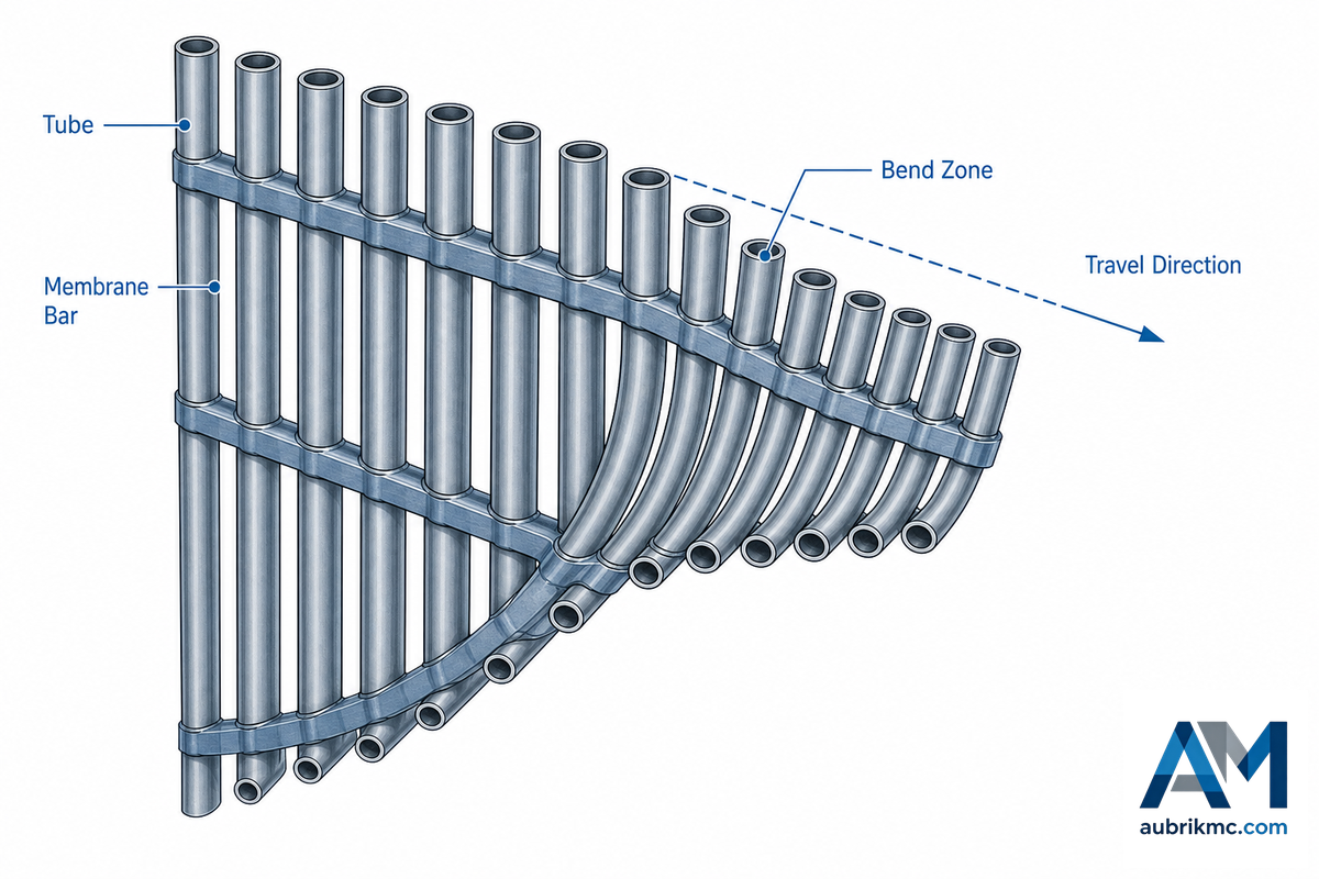
Boiler tube panel is a combination of the elements for pressure parts, with fins and/or membrane if needed. It’s purpose and accepting basis comes from the boiler’s design package. This differs from the work place and decision regarding the selection of a flat sheet metal piece. The choice to define a boiler tube panel matters before anyone talks about forming because an incorrect family selection can steer a review into incorrect measurements, jargon and the incorrect documentation of release.
At a boiler-panel production line, a wrong family choice creates both a release risk and a rework problem because tube layout, material traceability, and assembly interfaces must follow the drawing. The 60 mm outside-diameter and 3 mm wall research specimen cited below is an illustration of why geometry needs a stated basis, not a substitute for the applicable project requirement. Aubrik’s boiler tube-panel support page belongs to this drawing-led context; it is not evidence for a generic sheet-metal panel-bender decision.
Water-wall manufacturing patent documentation describes tube-and-fin panel subassemblies and their merging into a wall panel. Inspection guides for boilers link drawing-based approved forming and finishing inspections. For a fabrication team, the test of the work force becomes straightforward: can the part in question be recognized by water wall drawing, tube layout, interfaces, and pressure part documents? If yes, treat it like a boiler tube panel instead of a sheet metal Panel-bender decision.
Start With the Approved Water-Wall Drawing
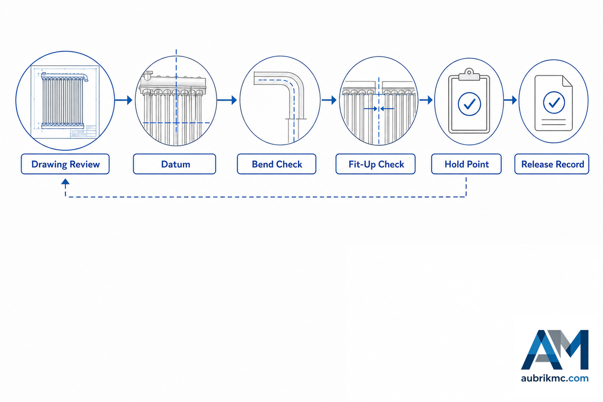
Prior to forming, be familiar with the correct drawing and ensure the following is established: Panel’s orientation, Tube Layout, Overall Envelope, Openings, Interface Points and the Reference Features where measurements should be taken. An accurate measure may be rendered pointless if the referenced datum isn’t included in the set or an incorrect revision is referenced.
Published boiler inspections guidelines advise drawing verification of final dimensions and formed pieces. It’s recommended that this become standard procedure. Put the relevant revision of the drawing on the check sheet, locate reference points and mark features where no clear criteria for acceptance can be found. These missing points require an engineering assessment and not reference to an unattached on-line instance of the part.
Which drawing features should be reviewed before a boiler tube panel is formed?
- Tube count, layout, centerline references, and orientation.
- Panel width, length, diagonal, offsets, and controlled openings.
- Bend locations, straight-leg requirements, clearances, and interfaces.
- Material identity, applicable procedure references, and required records.
- Project assigned:Hold points, witness points, inspection points, or test points.
Turn the Drawing Into a First-Article Plan
Make the primary article serve the purpose of the launch decision rather than just an exhibition of the product. Every point check will have an owner before the first tube has been formed. This method prevent common errors, such as identifying a variance only after assembly and having to search for the original setup condition, revision of drawing, and inspection conditions at the time the defect occurred.
7-Point Panel Release Framework
Turn the blueprint into a document for sharing: fill in all fields in the original project planning card once appropriate data is available from the project.
| Check | What to record | Why it changes the release decision | Owner |
|---|---|---|---|
| 1. Drawing revision | Approved revision and issue date | Stops work from following superseded geometry | Engineering |
| 2. Panel identity | Panel mark, orientation, and assembly location | Keeps inspection evidence tied to the intended component | Production |
| 3. Reference plan | Datums and measuring points | Makes later checks repeatable | Quality |
| 4. Material record | Heat or traceability reference required by the job | Separates material control from geometry control | Quality |
| 5. Bend record | Locations, method, observed condition, and reviewer | Exposes a bend issue before assembly conceals it | Production / Quality |
| 6. Fit-up hold point | Condition to inspect before joining | Prevents welding from locking in a mismatch | Welding supervision |
| 7. Release path | Required documents, escalation route, and sign-off | Prevents an incomplete record from moving downstream | Project quality lead |
This card may serve as a handoff between engineering, production, quality and procurement teams. Procurement can see which documentation needs to arrive with the material; the plant team can see which condition needs to be maintained; and quality can see which evidence is required for the release package.
Check Bend Geometry Before Panel Assembly
After a bend has been produced, evaluate the feature against the approved drawing and the applicable project requirements before assembly complicates any required access or correction. Common bend quality categories include profile, clearance, ovality, wall thinning or thickening, springback and surface condition. Various studies conducted by independent manufacturers identify a number of these phenomena as tube-bending processes, however, an applicable acceptance criteria is typically specified on a project-by-project basis.
In a public boiler inspection process, there are similar checks referenced for R/D ratio, ovality, thickness, visual inspection and final dimensions referenced to an approved drawing. A key part of this is documenting where the measurement was taken, how the evaluation was conducted, what drawing requirement the check references and the individual that approves or escalates it. Don’t merely borrow a percentage from another owner’s specification to become your boiler-panel release requirement.
Public numbers show variation; they are not your release values
There are many publicly available sources that illustrate measurement of a field without providing acceptance for your project’s criteria. Below are a few examples written in source specific, not advisory form. It illustrates the key takeaway for both the procurement and quality role; that they need the governing drawing, specification, and test plan before copying a number into their check sheet.
| Public source example | Number shown by that source | What it proves | What it does not prove |
|---|---|---|---|
| Open wall-thinning review | 1% outer-diameter tolerance example below 50 mm | Standards may vary by product and size | Your project’s bend acceptance value |
| Open wall-thinning review | 12.5% wall-thickness example and a <20% thinning example | Material and geometry affect published limits | A universal boiler-panel rule |
| General ovality guide | 4% stated standard; 1.5%–8% cited end-use range | Generic tube applications use different limits | The correct water-wall tolerance |
| General ovality guide | 2 in example shown as about 50.8 mm; 1.975 in as about 50.2 mm; 0.025 in as about 0.64 mm | Even a simple generic example depends on a stated measurement method | A permitted conversion or acceptance value for your panel |
| General tube-bending guide | ±0.1°, ±0.25°, and ±1.0° examples | Reported performance depends on the process context | A guarantee for this panel geometry |
| General tube-bending guide | 1.5D–2.5D suggested CLR range | Radius guidance depends on material and tooling | A project-approved bend radius |
| Independent bending study | 60 mm outside diameter and 3 mm wall in its test material | Geometry affects observed bending behavior | Performance for a different tube size or material |
| Open wall-thinning review | 0.02466 kg/m is one cited unit-mass factor in a reviewed calculation | Researchers define calculation inputs explicitly | A release calculation without the applicable project basis |
| U-tube supplier page | Up to 9 m straight legs and a ≤5% listed value for one product range | Supplier records can include geometry-specific data | An equivalent requirement for a boiler panel |
| Water-tube boiler standard catalogue | 2021 edition; 102-page workmanship standard | Water-tube workmanship has its own standards context | A free interpretation of that standard |
| Boiler inspection procedure | 2025 public code edition check | Revision control is a release input | A replacement for project engineering |
Sample sources: open wall-thinning review, general ovality guide, general tube-bending guide, independent bending study, U-tube supplier page, water-tube boiler standard catalogue.
What should be verified after a boiler tube-panel bend?
- Check that the bend location and orientation match the approved drawing.
- Required clearances and straight-leg interfaces remain available for assembly.
- Roundness, wall condition, and surface condition is checked according to the process specified by the project.
- Record each measurement against the correct panel and drawing revision.
- Any deviations are investigated and corrected prior to compromising assembly or welding processes.
Verify the Panel as an Assembly
Tube-level results don’t eliminate the need for assembly-level inspections. When tubes, fins or membrane elements are assembled, the resulting panel must be verified against the drawing as it should appear. That can, depending on the project, include dimensions such as tube pitch, overall width, diagonal measurements, openings, orientation, or the condition of mating elements, as described in the project’s drawing.
This release sequence is designed to go beyond a “pass/fail” entry and provides a defined role for each buyer at various points before time, money, or effort has been committed to the job.
First-Article Release Ladder
| Level | Question to answer | Evidence to retain | Decision |
|---|---|---|---|
| 1. Scope | Is this the intended boiler panel and revision? | Drawing and panel identity | Proceed or stop |
| 2. Material | Are required material records available? | Project-required traceability reference | Proceed or hold |
| 3. Set-up | Are the stated datums and reference points in use? | Set-up/check-sheet entry | Proceed or reset |
| 4. Bend | Does each controlled bend meet its stated basis? | Location, method, result, reviewer | Accept or escalate |
| 5. Envelope | Does the assembly match controlled dimensions? | Assembly measurement record | Accept or correct |
| 6. Fit-up | Are joints ready for the qualified joining route? | Hold-point record | Release or rework |
| 7. Required examination | Does the plan call for NDE or another examination? | Method, timing, acceptance basis | Schedule or document N/A |
| 8. Required testing | Does the code, contract, or test plan call for pressure testing? | Test requirement and responsible reviewer | Schedule or document N/A |
| 9. Handover | Can a later reviewer reconstruct the decision? | Complete release package | Release or hold |
Confirm Tube-Fin Fit-Up Before Welding Locks In an Error
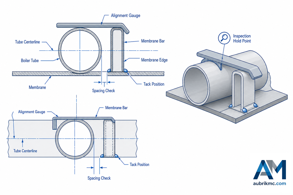
Even a minor mismatch upstream becomes difficult to detect and more costly to repair after welding has begun. Research into boiler tube panels shows why the potential distortion introduced by welding requires scrutiny, while the ISO 3834-2 catalogue provides the applicable welding-quality context for checking fit-up, joint preparation, welding procedures, personnel, and material before the welding operation begins.
For production assembly, a 60 mm outside-diameter and 3 mm wall research specimen is not a generic acceptance limit. Treating it as one would create a drawing-control risk and a costly mistake because a different tube geometry, material, or qualified procedure may apply.
A fit-up question isn’t whether one gap is ok, but whether the fit-up is ready for the qualified project procedure and the inspection points it identifies. If the drawing, procedure or inspection plan don’t provide that answer, escalate before committing to production. It’s more helpful than resolving a project-control problem with a machine setting.
⚠️ A flat-looking panel is not proof that the records, reference points, and weld-readiness conditions are correct.
Release the First Article With a Traceable Record
Test and inspection are different kinds of hold points: mechanical or non-destructive testing required by a tube material specification; forming checks to verify conformance with the drawing and procedure; and final-panel release tests required by the contract, code, component and IT plan. Don’t conflate them.
ASME identifies and publishes a current compilation of boiler and pressure vessel codes for materials, examination and qualification. These listings don’t prescribe the tests necessary for any specific project. They serve as reminders to use the correct code edition and send unresolved questions to the project’s authorized engineering or inspection representative.
When should a boiler tube panel move to project-required NDE or testing?
Only proceed when required by the applicable material specification, construction code, contract, procedure, or IT plan. Note the test method, acceptance criteria, timing, inspector and required record documentation. While this guide can’t determine hold points for your project, it helps you to ensure they aren’t overlooked.
If a Later Panel Deviates, Recheck the Process in This Order
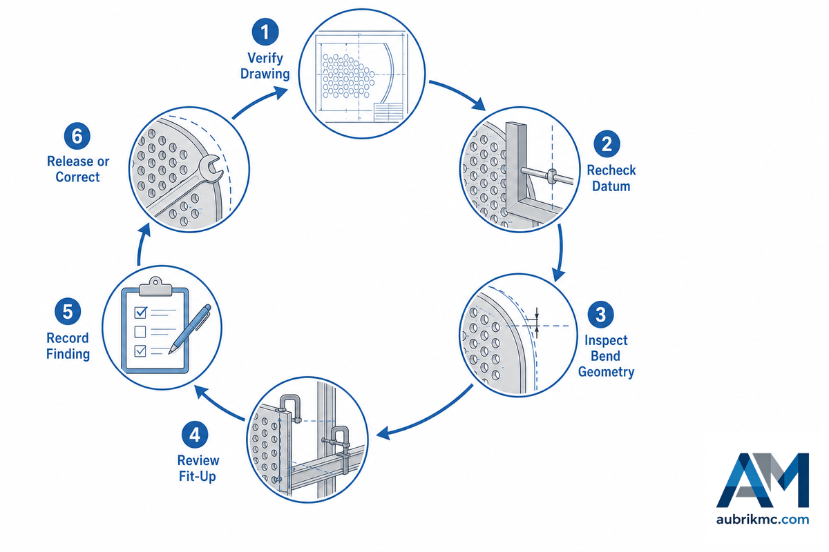
If a later panel differ from the approved first article, don’t immediately adjust the machine. The problem might be with a prior drawing, unstable datum, insufficient material information or an omitted fit-up hold point. Use the hidden bottleneck map to establish a clear sequence of checks among plant, quality, procurement and finance before rework drains time and material.
Hidden Bottleneck Map for Boiler Tube-Panel Release
| Visible symptom | Quick but risky reaction | Hidden bottleneck to check | Next owner |
|---|---|---|---|
| Wrong bend position | Re-bend immediately | Drawing revision or datum mismatch | Engineering |
| Unexpected ovality | Use another online tolerance | Applicable drawing/material/procedure basis | Quality |
| Surface mark at bend | Polish and continue | Project disposition and inspection requirement | Quality |
| Panel width differs | Force the assembly into position | Tube layout, reference plan, and fit-up sequence | Production |
| Diagonal differs | Correct one corner only | Accumulated geometry and assembly restraint | Engineering / Production |
| Opening will not align | Trim around the interface | Orientation, drawing update, and interface control | Engineering |
| Fit-up feels forced | Weld it to hold position | Joint preparation and qualified hold point | Welding supervision |
| Records are incomplete | Release from memory | Traceability and test-document obligations | Quality / Procurement |
| Repeat deviation appears | Treat it as isolated rework | First-article comparison and change control | Plant manager |
This buyer asset, not a diagnostic tool, helps all three departments (production, quality, commercial) to be on the same page about a given deviation.
In a production assembly, the 60 mm and 3 mm research example cannot diagnose a different panel. Treating it as a release limit creates a risk and a mistake because measured geometry and the approved drawing must be considered together.
Industry Outlook: Put Drawing-Linked Records Ahead of Generic Machine Claims
Because there’s no year-over-year public demand for this narrow boiler tube-panel niche, this guide doesn’t forecast growth. Instead, a useful outlook is a clean handoff from drawing to production to records – an area where first-article release packages can clarify a broad spectrum of information, though not offer a definitive productivity result.
Bring a copy of the current drawing revision and release card questions to your discussion of the drawing, acceptance criteria, and open forming questions using Aubrik’s panel bending solution for boiler tube panels.
Frequently Asked Questions
Before an engineering, production, or quality team uses these answers, treat any missing acceptance value as a risk and an escalation point because a generic guide cannot replace the drawing, material specification, and project test plan.
Is a boiler tube panel the same as a sheet-metal panel?
No. A boiler tube panel is an assembly of pressure-part tubes and, where applicable, membrane or fin elements that must match an approved boiler drawing and its interfaces. A sheet-metal panel is a different workpiece category. The same broad phrase can describe both, so the drawing, component function, and applicable project requirements must set the scope.
What should be checked before a first panel is formed?
Start with the current approved drawing revision and identify the tube layout, panel envelope, reference points, openings, orientation, and interfaces that affect the forming sequence. Confirm the material and traceability requirements supplied for the job, then define who records each first-article check. The release decision should follow the drawing and qualified project procedure rather than a generic machine setting.
Which dimensions should be verified after a water-wall panel is assembled?
The inspection record should focus on the dimensions and features called out by the approved drawing. Depending on the panel, that can include tube pitch, overall width, diagonal, openings, orientation, and connection interfaces. Measure the assembly as an assembly, not as a set of unrelated tubes. If a feature has no stated acceptance requirement, escalate the question instead of inventing a tolerance.
How should bend thinning and ovality be assessed?
Assess them against the applicable drawing, material requirement, and project procedure. A useful first-article record identifies the measurement location, method, observed condition, and reviewer. It shouldn’t convert a generic online value into a release criterion for a particular boiler panel.
When are NDE or hydrostatic tests required?
Material specifications may require tests for the tube itself, while NDE or hydrostatic testing for a finished panel depend on the component, code of construction, contract, qualified procedures, and the project’s inspection-and-test plan. When a requirement apply, the release package should identify the method, acceptance basis, timing, and responsible reviewer. Before handover, also confirm the drawing revision, the locations or features to be examined, the records that must accompany the result, and any hold or witness point defined by the project. Use approved project documentation to decide whether a dimensional check, visual inspection, NDE, pressure test, or a combination is required.
When should a fabricator request a forming-solution review?
Request a review when the approved drawing, acceptance criteria, workpiece geometry, or interface conditions leave an unresolved forming question. Bring the drawing revision and the first-article check requirements to that discussion. This keeps the request focused on the actual boiler tube-panel job rather than on generic sheet-metal equipment claims.