Get in Touch with Aubrik Company

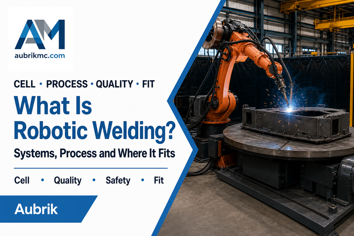
Robotic welding is an automated welding process in which a programmable robot positions a torch, electrode, or workpiece while a controlled welding system makes the joint. The robot arm is only one part of the solution: a production cell also needs process equipment, workholding, controls, safeguarding, and a repeatable way to present each joint.
What Is Robotic Welding?
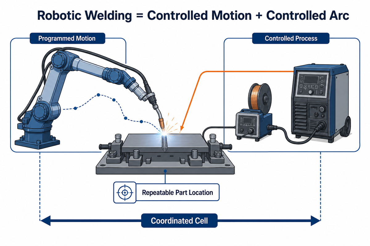
Robotic welding uses a programmable robot to control the movement and position of welding equipment or the workpiece during an automated cycle. It is not just about the robot: the welding power source controls current, voltage, wire feed rate, and waveform, while the robot controller manages position, path, speed, torch orientation, and sequence.
That distinction matters because a robot does not make a sound weld merely by following a path. TWI describes a basic robotic arc welding system as two linked subsystems: the welding equipment transfers energy to the workpiece, while the robot positions the heat source relative to it. A real production installation adds the workholding, safeguards, controls, software, and material handling needed to repeat that operation.
Robotic welding may be fully automated, with parts moving through a guarded cell, or operator-loaded, with each part placed in a fixture before a validated cycle begins. Depending on the application, a robotic welding system may use a conventional industrial robot, a collaborative robot, or a robot paired with a positioner that rotates the part.
Lists of the advantages of robotic welding focus on motion consistency, while lists of the benefits of robotic welding emphasize capacity and working conditions. Both depend on the same boundary: the complete robotic cell must control its inputs and detect conditions that fall outside the program.
In brief: Think of robotic welding as a controlled automation application, not just a six-axis robot arm and torch.
What Is Inside a Robotic Welding Cell?
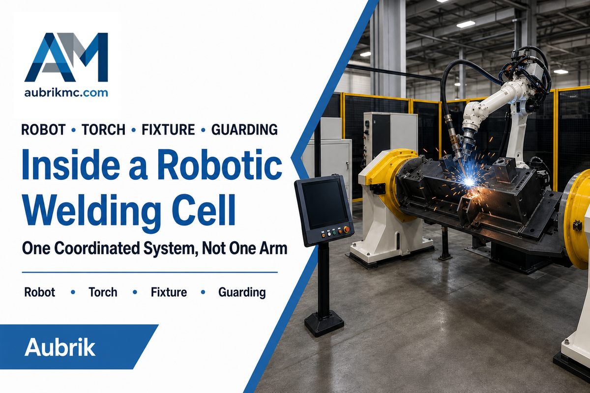
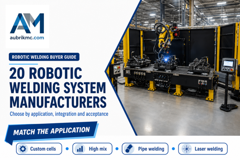
Each robotic welding cell consists of a robot, welding equipment, workholding, controls, safety, and sensors needed to make and verify a weld. The cell boundary must also assign ownership of loading, inspection, utilities, and recovery. Leaving any of these outside the project boundary creates an integration gap.
| Component type | What it controls | Typical failure if omitted or underspecified |
|---|---|---|
| Robot arm and controller | Path, travel speed, orientation, sequence | Insufficient reach, payload, access, or motion margin |
| Power source and process controller | Welding waveform and electrical parameters | Unstable transfer, heat input, or process response |
| Torch, wire feeder, and dress pack | Consumable delivery and tool position | Feed faults, cable interference, or tool-center-point drift |
| Fixture or positioner | Joint location and weld orientation | Fit-up movement, distortion, or poor torch access |
| Sensors and machine vision | Part presence, seam location, tracking, condition checks | Robot follows a valid program on an invalid part |
| Safety system | Access, stopping, interlocks, safe states | Uncontrolled exposure during production or service |
| Fume extraction and utilities | Air quality, gas, power, cooling, and grounding | Process instability or worker exposure |
| Inspection and data interface | Quality checks, traceability, upstream/downstream signals | Fast production of defects without containment |
Aubrik’s public robotic welding cell page groups the robot, welding source, positioner, safety enclosure, controller, and optional vision into one system.
This is useful first-party context. Final architecture, however, still depends on the actual part family and qualified welding procedure.
Decision point: Define the cell boundary before comparing robot models. An omitted subsystem is often more important than a small difference in robot specifications.
Which Welding Processes Can Robots Perform?
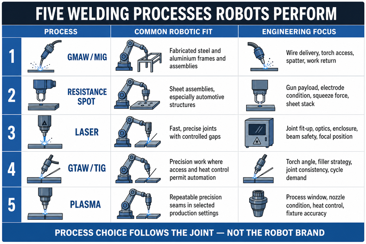
Robots can perform arc welding, resistance spot welding, laser welding, and selected TIG and plasma welding applications when the process, joint, and material presentation are suitable. Robotic welding is therefore a motion-and-control category, not one welding method. Arc welding robots, for example, coordinate torch motion with a separately controlled power source.
| Process | Common robotic fit | Engineering focus |
|---|---|---|
| Gas metal arc welding / MIG welding | Fabricated steel and aluminum parts, frames, assemblies | Wire delivery, torch access, spatter, work return, seam location |
| Resistance spot welding | Sheet assemblies, especially automotive structures | Gun payload, electrode condition, squeeze force, sheet stack |
| Laser welding | Fast, precise joints with controlled gaps | Joint fit-up, optics, enclosure, beam safety, focal position |
| Gas tungsten arc / TIG welding | Precision work where access and heat control permit automation | Torch angle, filler strategy, joint consistency, cycle demand |
| Plasma welding | Repeatable precision seams in selected production settings | Process window, nozzle condition, heat control, fixture accuracy |
Process choice is driven by metallurgy, joint design, required penetration, heat input, duty cycle, takt demand, and the acceptable process window. No robot can turn a process that is unstable on a representative sample into a stable production method. Start with a qualified welding process, then choose the robot and cell around it.
Those types of robotic welding use different equipment and control limits, as the table above shows. Resistance welding, for example, depends on electrode force and sheet-stack condition rather than the wire delivery used in a gas metal arc welding cell.
For a focused explanation of robot and package selection, use the robotic welding machine guide after the process and part family have been defined.
Core idea: Match the process to the joint first. “Robot compatible” does not mean every process is equally practical for the same part.
How Does Robotic Welding Work?
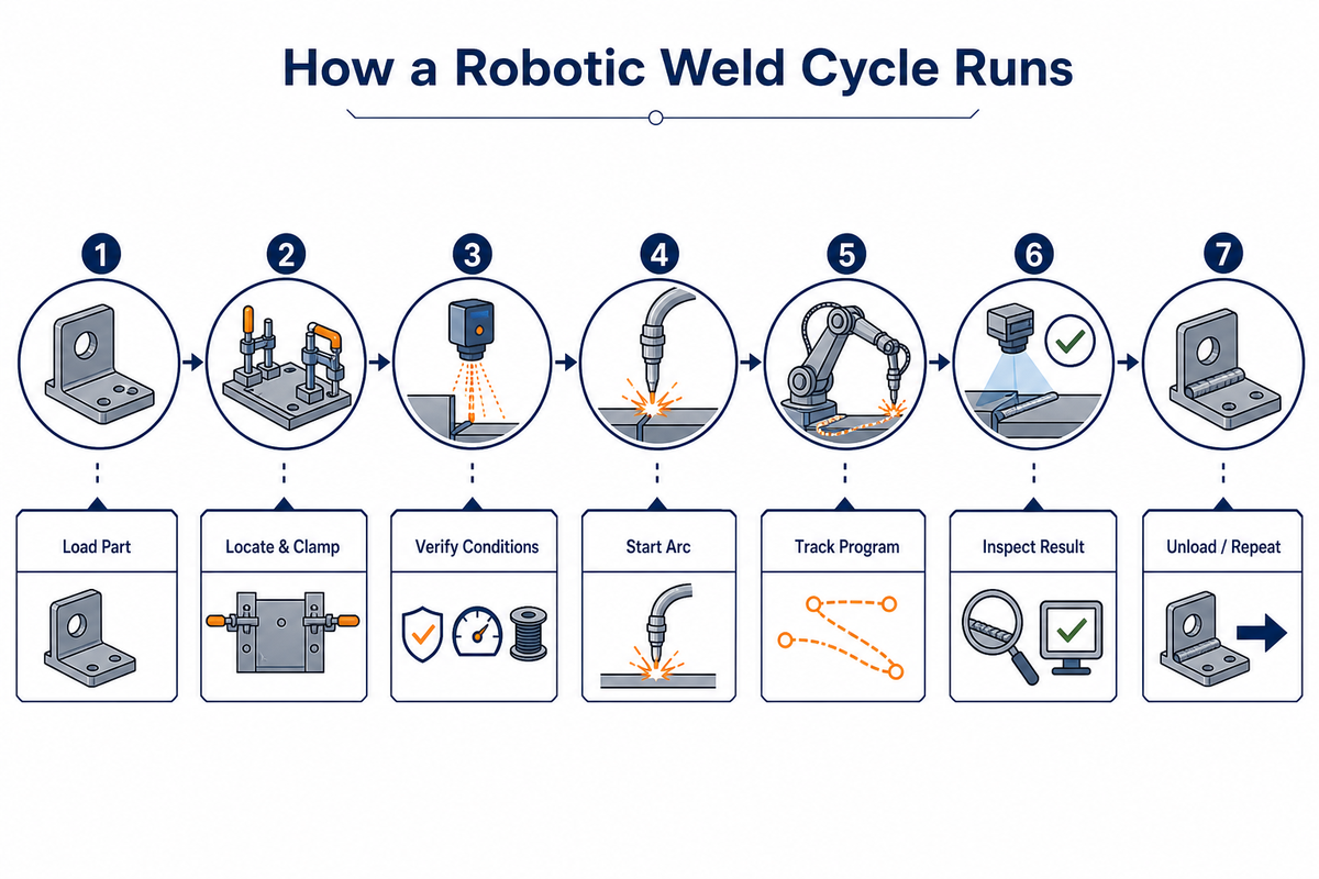
Robotic welding works by presenting a known joint, confirming the cell is ready, running a programmed motion-and-process sequence, checking the result, and returning the cell to a safe load state. A typical cycle has seven stages. Each stage has a defined ready, fault, and recovery condition.
- Load and identify the part. An operator or material-handling device places the workpiece in the fixture. Part-presence sensing prevents a wrong or missing component from entering the cycle.
- Clamp and locate. The fixture establishes the datums that place the joint inside the programmed or searchable zone.
- Select and validate the program. The controller confirms the correct recipe, safety state, utilities, wire, gas, and supporting equipment.
- Find the joint when required. Touch sensing, through-arc sensing, laser sensing, or machine vision may search for or track a seam within a defined envelope. TWI’s discussion of process and geometrical sensing also notes interference from arc light, heat, fumes, current, molten metal, and spatter.
- Execute the weld. The robot controller coordinates travel speed and torch attitude while the welding controller runs the qualified parameters.
- Inspect and contain. The cell records process limits or inspection results and prevents a known nonconforming part from flowing forward.
- Unload and reset. The robot moves to a verified safe location, clamps release, and the next cycle begins.
Robot programming can be done with a teach pendant, offline programming, direct demonstration in some cobot workflows, or a combination. In this robotic process, the welding torch, robot controller, and any workpiece positioner execute one coordinated recipe. Mature robotic automation treats that program as a production asset with revision control, recovery instructions, and a defined owner.
Process check: The visible arc is just part of the process. Loading, validation, sensing, inspection, and recovery define the good-part cycle time.
Which Parts Are Good Candidates for Robotic Welding?
Good candidates have joints the cell can repeatedly locate and access, plus enough production value to justify programming, workholding, validation, and changeover. Annual volume alone is not a reliable pass-or-fail rule. Part-family commonality and stable presentation matter as much as volume.
- Part presentation keeps formed and cut features in a known relationship to the fixture datums.
- Joint access lets the torch, robot wrist, cable package, and any positioner move without collision or singularity risk.
- Fit-up keeps gaps, mismatch, tack placement, and distortion inside the qualified process or sensing range.
- Family logic gives variants enough shared datums, joint types, and loading methods to keep changeover manageable.
- Quality criteria and inspection methods are known before robot programming begins.
- Production economics include loading, tack time, inspection, planned maintenance, and exception recovery alongside arc-on time.
Fixture strategy has an important boundary. NIST’s discussion of collaborative robots in high-mix, low-volume manufacturing explains that adaptation to variation in part position and size can reduce dependence on custom fixtures. It also notes speed, payload, and application-specific safety limits. In practice, control variation mechanically or detect and compensate for it inside a validated envelope.
Production volume still matters to the business case, but it does not remove part variation. A welding fixture, joint tracking, seam tracking, or a combination must keep the joint inside the validated range. When speaking with a system integrator, identify what is controlled mechanically and what is measured in each operation.
Document these inputs before comparing conventional robots, cobots, and positioner-led routes with an integrator; Aubrik’s equipment selector is the entry point for the equipment families involved.
Suitability rule: A lower-volume, repeatable part family may make a better candidate for robotic automation than a high-volume part with highly inconsistent joint locations.
Robotic Welding vs. Manual Welding
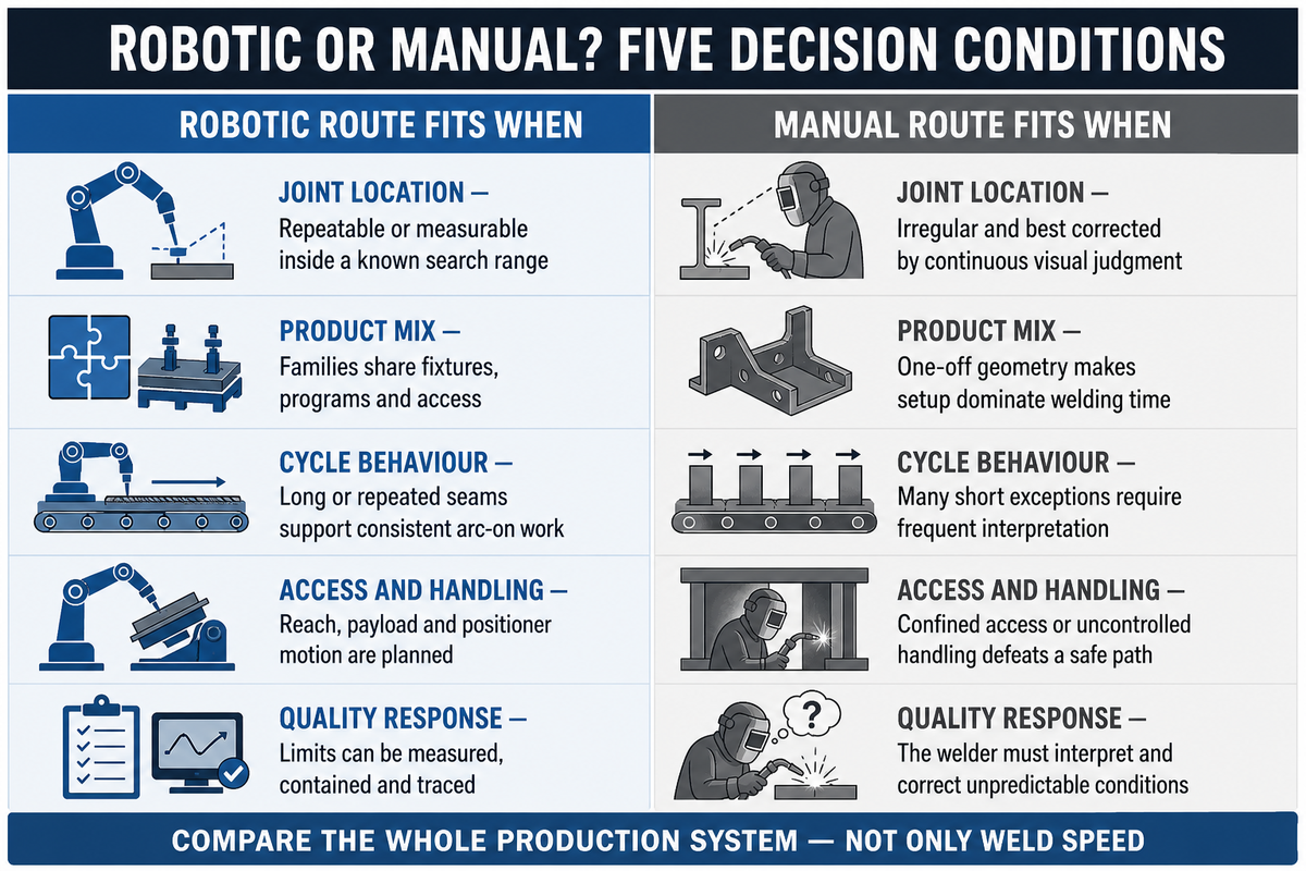
Robotic welding usually fits repeatable parts and production runs. A human welder remains more adaptable when parts are irregular, access is constrained, production is one-off, or changing process conditions require continuous judgment. Compare accepted-part cost and cycle time, not welding speed alone.
| Decision condition | Robotic route tends to fit when… | Manual route tends to fit when… |
|---|---|---|
| Joint location | Repeatable or measurable inside a known search range | Irregular and best corrected by continuous visual judgment |
| Product mix | Families share fixtures, programs, and access | One-off geometry makes setup dominate welding time |
| Cycle behavior | Long or repeated seams support consistent arc-on work | Many short exceptions require frequent interpretation |
| Access and handling | Reach, payload, and positioner motion are planned | Confined access or uncontrolled handling defeats a safe path |
| Quality response | Limits can be measured, contained, and traced | Welder must interpret and correct unpredictable conditions |
Consistent robot motion can raise productivity and throughput by reducing variation in travel speed, torch position, joint approach, and sequence. Motion equipment is only one part of these welding applications, and a human welder remains essential to them. In production, skilled welders still develop procedures, handle difficult jobs, diagnose defects, make quality decisions, solve process problems, and support maintenance. During labor shortages, automation can shift that expertise toward higher-value work; it does not make welding skill obsolete. Changeover time must still be included when comparing part families in fabrication.
For a project-specific cost estimate, include capital cost, loading, changeover, inspection, rework, recovery, and accepted-part cycle time. Aubrik publishes an automation return-on-investment page covering those cost factors.
Comparison rule: Choose the robotic system solution that controls the whole production chain, not just the quickest possible torch motion along the joint.
What Controls Robotic Weld Quality?
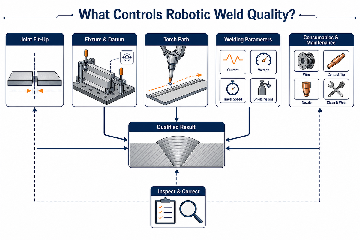
A qualified welding procedure, joint condition, tool calibration, workholding, consumables, electrical path, sensing, and inspection control robotic weld quality. Robot repeatability alone cannot keep the cell from repeating a bad condition, and by itself it does not deliver consistent welds.
A practical control plan would examine these issues:
- qualified procedure variables and responsible welding personnel;
- joint preparation, gap, mismatch, tack welds, and cleanliness;
- fixture location, clamp sequence, wear, and thermal distortion;
- tool-center-point checks, torch-neck condition, liner, tip, and nozzle;
- wire feed rate, shielding gas, return path, power supply/heat input;
- tracking or search method, including conditions for a failed search;
- inspection, test frequency, traceability, and containment rules; and
- preventive maintenance with calibration and consumable change triggers.
The following table is an evidence-capture example, not a set of acceptance criteria or process recommendations. Every number is illustrative and shows how a team might record measured inputs before approving a production release.
| Evidence source | Record before release | Illustrative value only—not an acceptance limit |
|---|---|---|
| Procedure qualification | Current and voltage | 230 A; 24 V |
| Representative joint sample | Gap and mismatch | 0.8 mm; 1.2 mm |
| Fixture capability study | Repeated joint location | 0.5 mm |
| Torch check | Tool-center-point drift | 0.4 mm |
| Shielding gas record | Flow | 18 L/min |
| Cycle observation | Arc-on and load delay | 45 sec; 20 sec |
| Production observation | Accepted-part sample | 50 parts over 2 hr |
| Maintenance log | Check interval | 8 hr; 7 days |
Path Robotics, Inc.’s U.S. Patent 11,648,683, titled “Autonomous welding robots,” describes a proposed method for identifying potential seams, aligning geometric models with parts, calculating a path, and executing it. That is evidence of a sensing-and-control chain, not proof of production capability: adaptive features do not eliminate the need for workholding or process qualification.
Quality rule: Sustained repeatable welds come from controlled inputs, validated tools, and containment—not from the robot spec sheet alone.
How Is a Robotic Welding Cell Kept Safe?
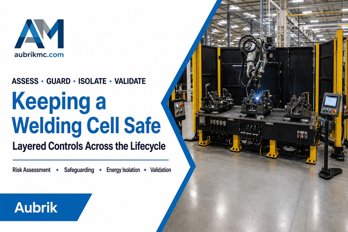
A robotic welding cell is kept safe through application-level risk assessment, engineered safeguarding, controlled access, hazardous-energy procedures, fume control, and validation across production and service tasks. Robot motion is only one hazard source inside the cell. The risk assessment must also address arc light, fumes, heat, and maintenance access.
OSHA’s robotics standards page states there is no robotics-specific OSHA standard and points to relevant general-industry standards and consensus standards, including robot-system integration, machine guarding, hazardous-energy control, and robotic arc-welding safety. ISO’s ISO 10218-1:2025 listing is a current reference, but customers still need to verify national acceptance and the integrator’s validation scope.
Robot and positioner motion
Reach, trapping, ejection, unexpected restart, gravity, and stored energy.
Welding process
Arc light, heat, spatter, hot workpieces, electrical energy, shielding gas, and fumes.
Lifecycle tasks
Loading, teaching, recovery, tip change, fixture service, troubleshooting, and maintenance.
Protective functions
Guards, screens, interlocks, scanners, safe stops, lockout, extraction, and validated restart logic.
Lifecycle analysis is practical, not academic. OSHA’s hazard-recognition material includes fatal exposure during maintenance inside a robot’s operating envelope. Any risk assessment that excludes manual tasks misses the occasions when operators are likely to access the cell.
Operator safety is also impacted by exposure to the welding process. Fume extraction, screens, work-return design, and controlled recovery can support a safer work environment, but they require validation for specific tasks and materials.
Safety rule: Safety measures are validated cell functions. They must work for the welding process and any human interaction, not only robot contact.
Cobot Welding vs. Industrial Robot Welding
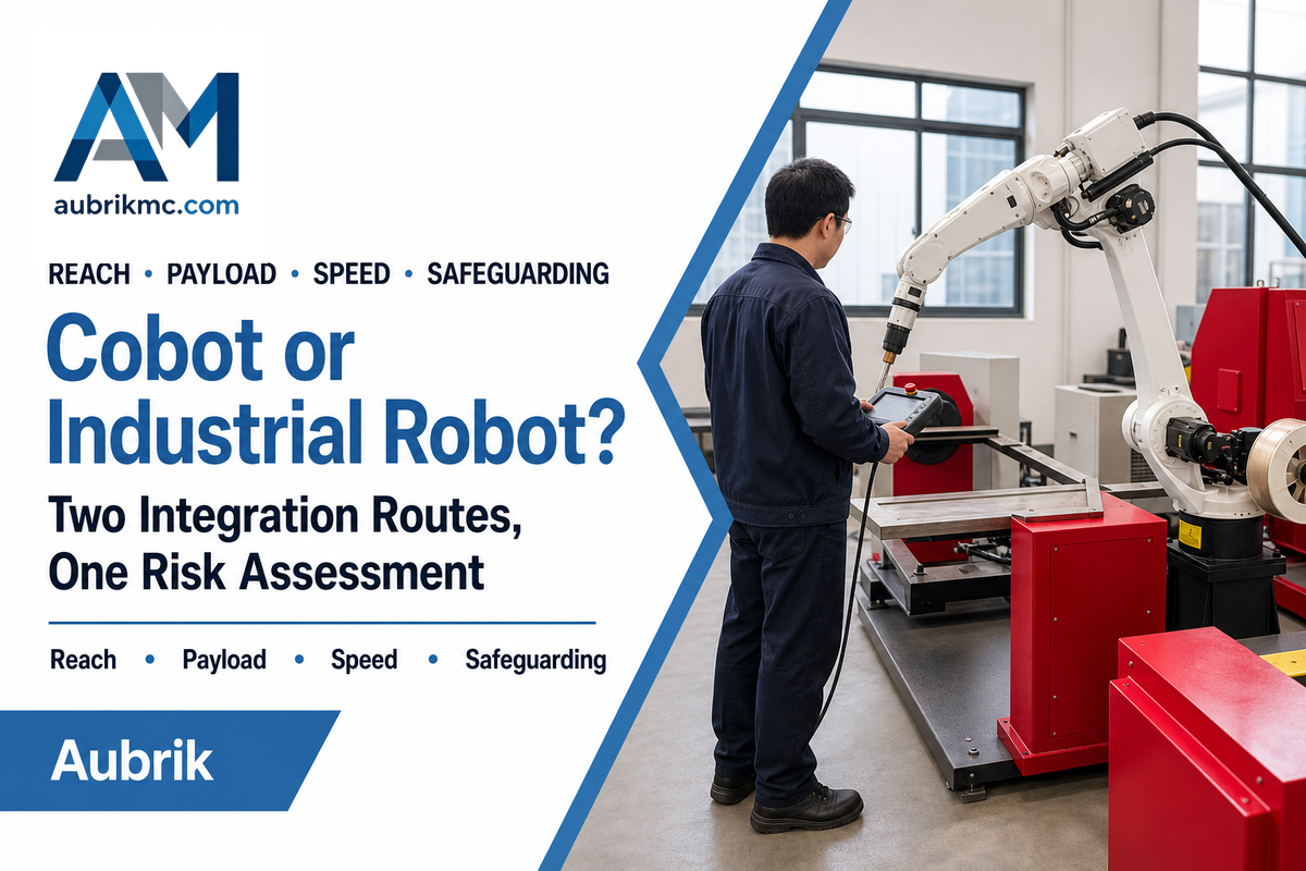
Cobot welding allows easier interaction and versatile redeployment, while conventional industrial robot welding supports higher payload, speed, reach, and protected production; neither route is automatically safer or better. Task and risk assessment should dictate the correct option. Cell layout and production duty then determine the practical tradeoff.
| Factor | Cobot welding | Industrial robot welding |
|---|---|---|
| Interaction model | Designed for selected collaborative functions and simpler teaching | Typically separated from people during automatic motion |
| Production emphasis | High-mix cells, assisted workflows, flexible deployment | Sustained duty, larger envelopes, higher payload or speed |
| Safeguarding | Task-specific; welding hazards may still require screens or separation | Guarded enclosure and interlocked access are common |
| Main tradeoff | Flexibility against speed, payload, and reach limits | Production capability against a larger integration footprint |
“Collaborative” describes a function and design approach; it does not remove the hazards of arc radiation, fumes, hot metal, sharp edges, or powered positioners. Every cobot welder must still be integrated into a complete process. Review cobot welding options together with the part family, human tasks, and protective measures.
Selection rule: Select the production mode and interaction first; then validate all hazards in the complete process.
The 5-Input Part-to-Cell Readiness Framework
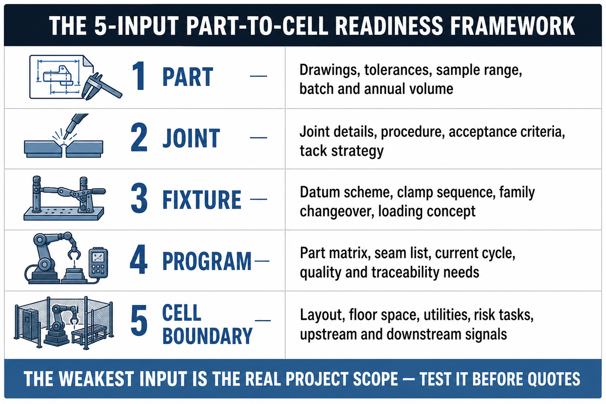
The 5-Input Part-to-Cell Readiness Framework identifies the constraint that will decide if robotic welding is feasible: Part, Joint, Fixture, Program, and Cell boundary. It converts a vague request for a robot price into an engineering brief.
Every question raised in the sections above collapses into these five measurable inputs. Its fixture and cell-boundary inputs also reflect the application-specific speed, payload, and safety limits noted in NIST’s MEP blog discussion of collaborative robots.
| Input | Ask this | Evidence to send an integrator |
|---|---|---|
| Part | How much do cut, formed, machined, and assembled features vary? | Drawings, tolerances, sample range, batch and annual volume |
| Joint | Can the process tolerate the actual gap, mismatch, access, and distortion? | Joint details, procedure, acceptance criteria, tack strategy |
| Fixture | What locates the joint, and where is adaptive sensing preferable? | Datum scheme, clamp sequence, family changeover, loading concept |
| Program | How many recipes, searches, exceptions, and recovery paths are required? | Part matrix, seam list, current cycle, quality and traceability needs |
| Cell boundary | Who owns loading, positioners, utilities, extraction, safety, inspection, and interfaces? | Layout, floor space, utilities, risk tasks, upstream/downstream signals |
| Measurement record | Illustrative format only, not a machine recommendation |
|---|---|
| Production and cell | 6 mm material; 5,000 parts/year; 50 parts/run; 1,200 mm weld; 8 min/part; 20 min/run changeover; 30 m² cell; uptime ratio 0.85 |
| Utilities and commissioning | 45 kilowatts; 15 L/min gas; 400 V; 80 A; 60 Hz; 6 bar; 30 sec clamp check; 2 min recovery; 4 hr observation |
| Access and planning | 25 kg fixture module; 1,200 rpm service tool; 8 mm reject threshold; 150 cm clearance; 1.5 m aisle; arc-on ratio 0.70; 20 days spares lead time; 4 years planning horizon |
Score each project input as known and stable, measurable but variable, or unknown, and set the measurement resolution you will record them at — for example position in 1 mm increments, handled load in 1 kg increments, short delays in 1 sec increments, and changeover in 1 min increments. Remove all illustrative table values and replace them with measured project data; these are formatting examples, not acceptance limits.
One unknown input does not automatically reject the project, but it becomes the first test. A trial weld, fixture study, sensing test, reach simulation, or risk review should precede the final capital estimate.
When the five inputs are determined, a welding return-on-investment and payback calculation can use realistic good-part cycle time, labor division, rework, maintenance, and changeover assumptions.
Readiness rule: The weakest of the five inputs is usually the real project scope. Test it before soliciting quotes.
Frequently Asked Questions
Is robotic welding faster than manual welding?
Robotic welding can be faster when parts arrive in a repeatable condition and the cell maintains useful arc-on time. It can reduce variation in travel speed, torch angle, and sequence. That does not make every cell faster. Loading, fixturing, tack welds, program changes, inspection, and recovery from poor fit-up can dominate the cycle. Compare total good-part cycle time, not robot travel speed alone.
What is the main disadvantage of robotic welding?
The main disadvantage is the engineering effort required to control or measure the inputs. Robots repeat programmed paths even when a joint moves because of inconsistent cutting, forming, or clamping. Work shifts from hand correction at the torch to preparation, fixtures, robot programming, sensing, maintenance, and cell safety. High-mix work with uncontrolled variation may remain better suited to manual or assisted workflows.
Do you need a welder to operate a welding robot?
You still need welding competence even when the routine operator does not manually run the torch. Someone must develop and qualify the weld procedure, set process parameters, confirm the torch and work return, evaluate defects, and decide when a program or fixture needs correction. Robot programming and production operation can be separate roles, but automated welding does not remove welding engineering responsibility.
Can a welding cobot work without guarding?
Not automatically. Arc light, heat, fumes, fixtures, and positioners create separate hazards, and a task-specific risk assessment decides whether the cell needs screens, interlocks, restricted zones, scanners, or conventional guarding; OSHA’s robot hazard guidance also covers exposure during work inside the robot envelope.
What information should I send to a robotic welding integrator?
Send the full production and quality boundary, not only one drawing. Include part drawings, materials, product-family variants, annual and batch volume, joint types, welding procedure requirements, allowable variation, representative samples, current good-part cycle, quality and inspection criteria, available floor space and utilities, upstream and downstream material flow, loading method, operator tasks, safety constraints, and the data or traceability expected from the cell. Add photos of current fixtures, defects, and loading; name the responsible procedure and quality owners; and describe how nonconforming parts are contained. Those details let the system integrator test reach, workholding, sensing, inspection, and recovery against real production rather than one ideal sample.
Conclusion: Start With the Joint, Not the Robot
Robotic welding places an automated welding operation inside a controlled, programmable cell. It works best when variation in the part and joint is either limited or measured within a validated sensing window. Ask a more useful question than “Can a robot weld?”: “Can this complete cell repeatedly locate, weld, inspect, and recover this joint?”
Complete the 5-Input Part-to-Cell Readiness Framework before requesting a quote. If the best route is not yet clear, compare Aubrik’s robotic welding machine options against your part, process, and cell-boundary requirements.
Prepare a useful project brief
Send Aubrik representative parts, drawings, weld requirements, production volume, current cycle data, and the five readiness inputs. That gives the engineering team a stronger basis for a cell concept than a robot model request alone.
Related Aubrik resources
- Robotic welding cell guide: sizing and layout
- Cobot welding guide: payload, reach and guarding
- Welding robot cost guide
References & Sources
- TWI, Robotic Arc Welding
- OSHA, Robotics Standards
- OSHA, Robotics Hazard Recognition
- ISO, ISO 10218-1:2025 listing
- NIST, High-Mix/Low-Volume Manufacturers and Collaborative Robots
- Boldrin et al. (2024), “Seam Tracking and Gap Bridging During Robotic Laser Beam Welding via Grayscale Imaging and Wobbling,” Robotics and Computer-Integrated Manufacturing 89, 102774, DOI 10.1016/j.rcim.2024.102774
- Path Robotics, Inc., US11648683B2, “Autonomous Welding Robots”