Get in Touch with Aubrik Company

How Does a Pipe Welding Manipulator Work, and Which Type Do You Need?

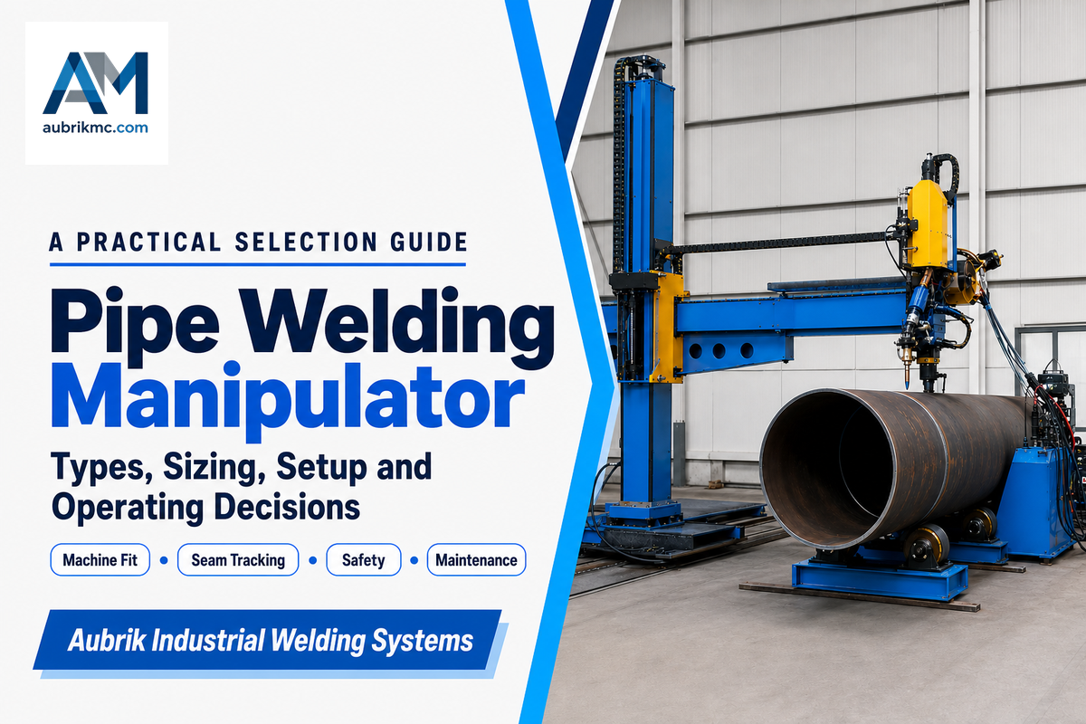
A pipe welding manipulator is a column-and-boom or cantilevered machine that carries a SAW or GMAW torch head along a fixed or traveling path while the pipe stays still or turns on a separate rotator, so the joint gets a consistent pass without a welder walking the seam by hand. Shops that fabricate spools, pressure vessels, or pipeline sections use one to hold weld speed, arc position, and bead geometry steady across a full production run.
This guide focuses on the pipe-specific engineering questions: how to size a manipulator against pipe OD and wall thickness, how it pairs with a rotator, which welding code actually governs a pipe joint, and what breaks a setup if it’s installed or run incorrectly. If you already know you need a manipulator and want to see Aubrik’s own equipment, the Pipe Welding Manipulator solution page covers the product line directly.
By Cherry · Updated August 2026
Quick Specs Across the Pipe Manipulator Range
- Pipe OD coverage: 50 mm to 3,000 mm across four duty classes
- Positioning precision: ±0.1 mm on the ABOKE FWM series
- Welding processes: SAW and GMAW, dual-head capable
- Column and boom stroke: 1,000×1,000 mm up to 8,000×8,000 mm
- Torch travel speed: up to 300–1,400 mm/min depending on model
In short
A pipe welding manipulator is a boom-mounted torch carrier that moves the arc along a pipe seam while the pipe itself stays fixed or turns on a separate rotator, producing a repeatable circumferential or longitudinal pass without a welder tracking the joint by hand.
TL;DR
- A manipulator carries the torch; a rotator turns the pipe, and most pipe cells use both together (H2-2).
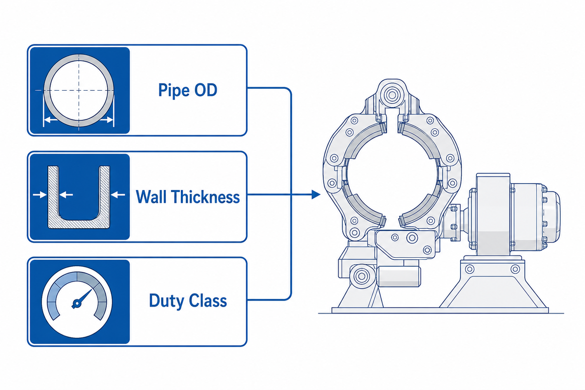
- Size by pipe OD, wall thickness, and duty class, not by boom capacity alone (H2-3).
- Real result: one ABOKE FWM-0404 cell cut cycle time from 8h to 4.8h and raised AWS D1.1 first-pass rate from 85% to 99.5% (H2-3).
- API 1104 and the ASME B31 family govern pipe and pressure-boundary welds, a different code family than the AWS D1.1 structural code (H2-5).
- 29 CFR 1910.146 confined-space rules apply the moment anyone enters a large-bore pipe for setup (H2-8).
1. What a Pipe Welding Manipulator Actually Moves, and What It Doesn’t
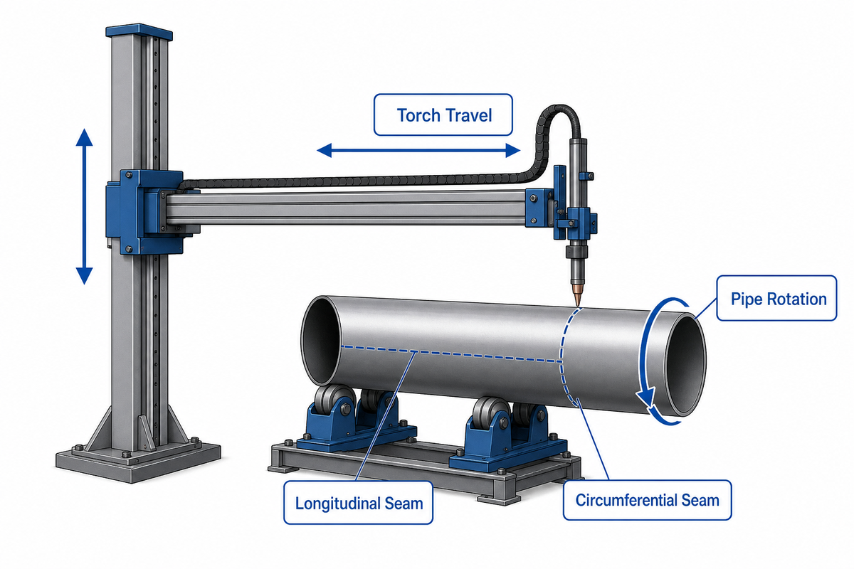
A pipe welding manipulator moves the torch, not the pipe. Its column-and-boom frame carries the welding head up, down, and along a horizontal boom so the arc tracks a seam while the boom’s own drive holds travel speed and torch angle constant. On a pipe job, the machine typically handles one of three seam geometries: a circumferential seam that rings the pipe, a longitudinal seam that runs parallel to the pipe axis, or a compound or spiral seam that combines both directions on a helically wound or mitered joint.
Servo motors drive the column, boom, and travel car that carries the welding torch around the cylindrical pipe, producing a uniform weld across pipe welding applications and pipe welding tasks that span small spools to shipbuilding sections. That combination is what separates automated or semi-automated cells from work that used to be manually operated.
- Circumferential seams usually need the pipe to rotate under a stationary or lightly traveling torch, which is why a manipulator is so often paired with a rotator.
- Longitudinal seams need the torch to travel the length of a fixed pipe, which is the manipulator’s boom doing nearly all of the work alone.
- Compound or spiral seams need both motions synchronized at once, covered in more detail in H2-9 below.
This works because the column drive, the boom carriage, and the control logic that holds torch angle and stickout are shared with non-pipe applications like flat-panel and structural welding. For a broader walkthrough of how a column and boom system works in general, see our column and boom manipulator guide. This article stays focused on what changes when the workpiece is a pipe.
2. Manipulator, Rotator, or Both: The Pipe-Specific Decision Framework
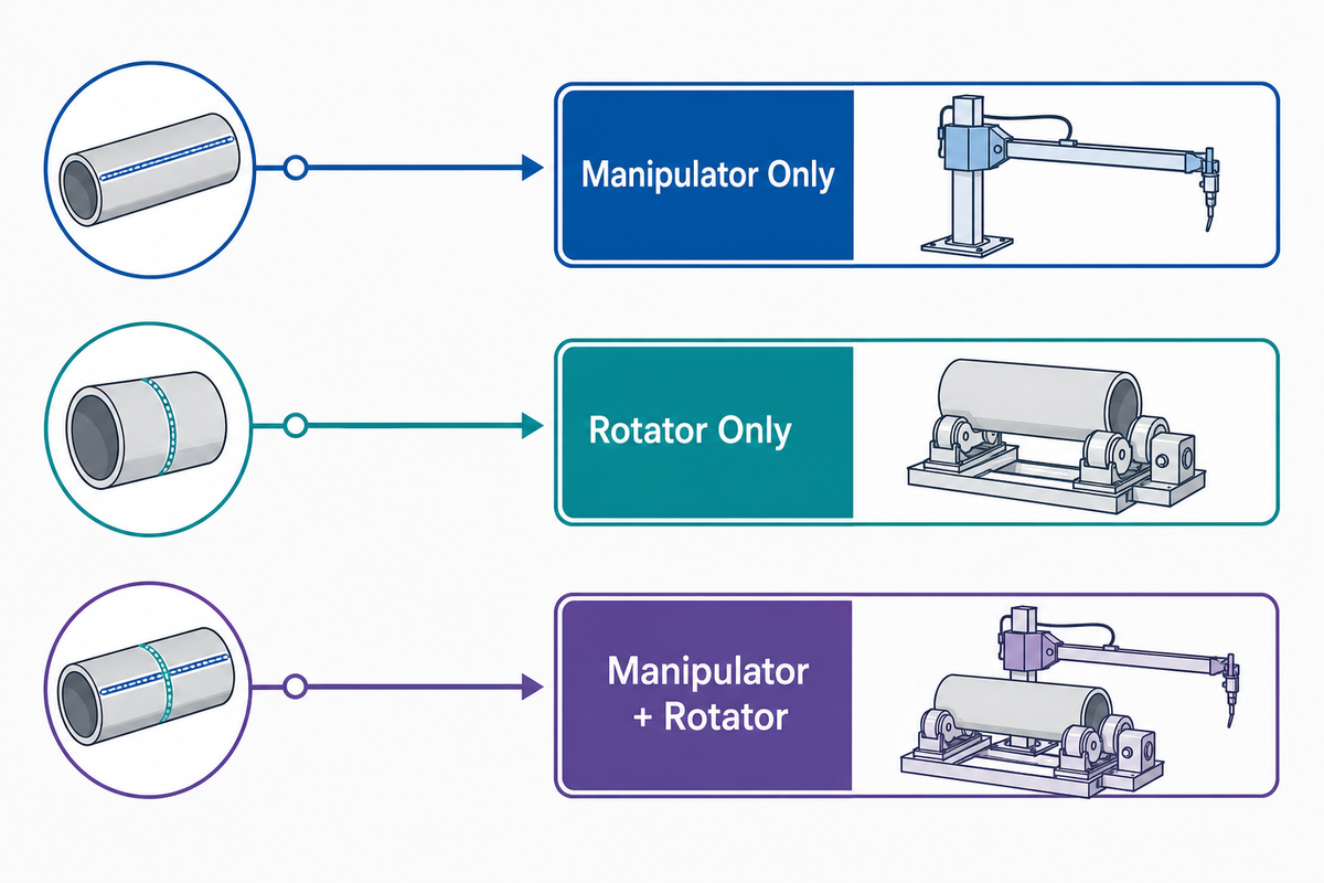
A manipulator alone covers a longitudinal seam on a pipe that stays put, a rotator alone covers a circumferential seam on a pipe that can spin freely under a fixed torch, and most production pipe cells actually need both machines working together because real pipe jobs mix seam types across a single spool run. The table below sorts this by seam geometry rather than by equipment category, so it stays specific to pipe work instead of repeating a generic manipulator-vs-positioner-vs-robot comparison.
| Seam orientation | Which machine moves | Typical pipe OD band | Single or dual machine | Typical process fit |
|---|---|---|---|---|
| Circumferential (girth) seam | Pipe rotates; torch stays fixed or drifts slightly | All ranges, most common on 200–1,500 mm | Dual: manipulator + rotator | SAW or GMAW |
| Longitudinal seam | Torch travels the boom; pipe stays fixed | All ranges | Single: manipulator only | SAW or GMAW |
| Compound or spiral seam | Both torch travel and pipe rotation, synchronized | Typically 300–3,000 mm | Dual: manipulator + rotator, speed-matched | SAW, dual-head capable |
In reality, most shops that run mixed pipe work end up owning both machines rather than choosing one. Without a rotator, a manipulator can’t finish a girth seam without manual pipe-turning between passes, and without a manipulator, a rotator can’t handle a longitudinal seam at all. The pairing question, and how the two machines keep their speeds matched, gets its own worked example in H2-9, a pairing practice consistent with AWS D10 recommended practice for pipe welding.
Established builders in this space, including Koike Aronson, Ransome, and Aubrik, sell broadly similar column-and-boom welding systems, though duty range and control options vary between models. Compact manipulators sometimes marketed under names like the Cricket-II manipulator or Scarab trade a smaller footprint for a lower duty ceiling, which can still be the more cost-effective choice for a shop that never handles large-diameter pipe. Automated welding systems at any of these tiers still depend on the seam-geometry logic in the table above.
3. Sizing a Pipe Welding Manipulator: OD, Wall Thickness, and Duty Class
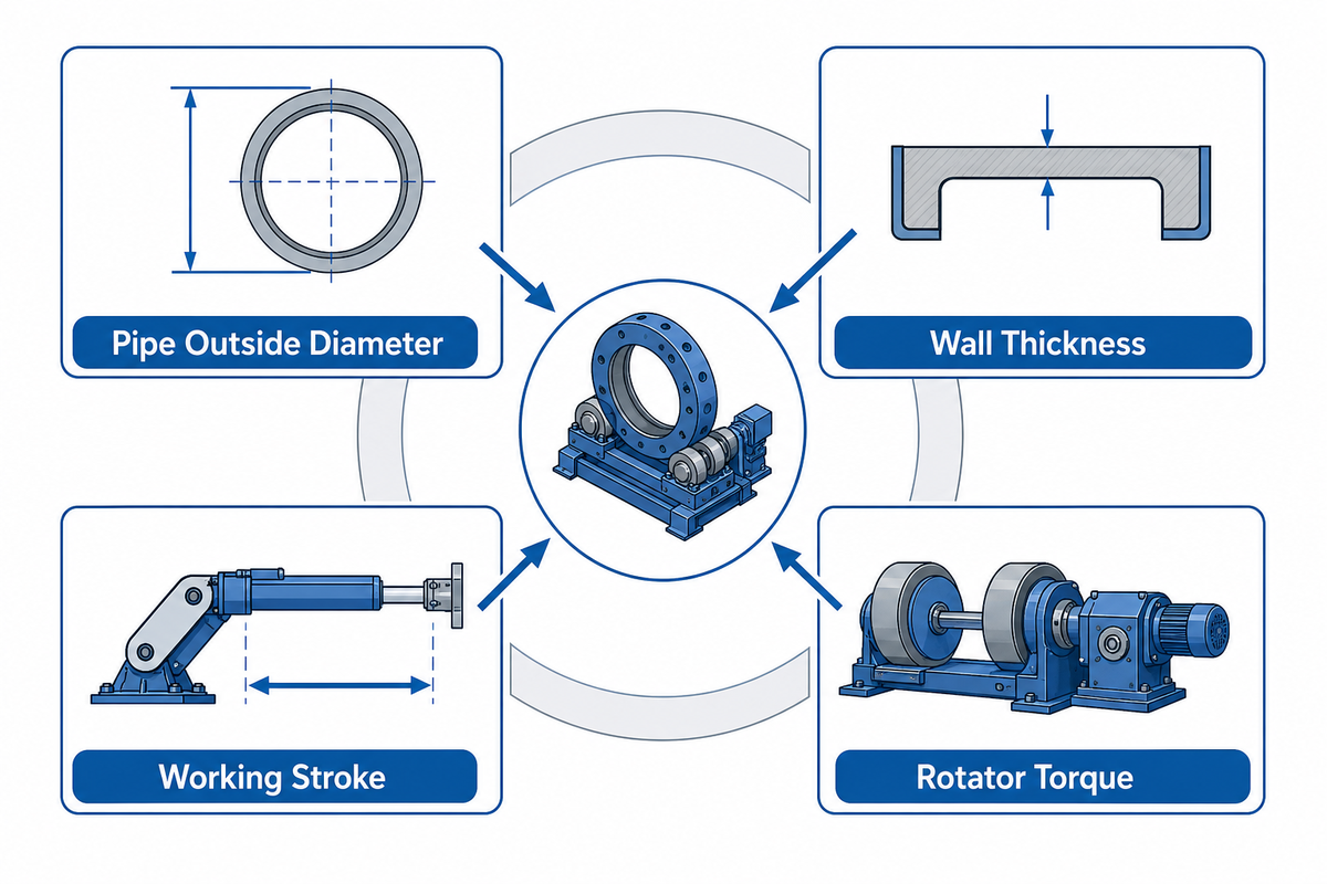
Four duty classes cover pipe OD from 50 mm to 3,000 mm, and the right one depends on the full envelope, pipe outside diameter, wall thickness and the resulting weight per meter, working stroke, and rotator torque together, not on the single largest number printed on a spec sheet. Sizing by headline boom capacity alone is a common shortcut, and it’s also the mistake most likely to leave a shop with a manipulator that can’t actually clear its own workpiece once fixturing and rotator load are added in.
50–3,000 mmpipe OD range across the ABOKE FWM series
±0.1 mmpositioning precision, all four FWM models
The table below lists real duty-class specifications rather than a generic small/medium/large split, so the OD and stroke numbers can be checked directly against a project’s pipe schedule.
| Model / class | Pipe OD range | Column & boom stroke | Load capacity | Torch travel speed | Process |
|---|---|---|---|---|---|
| ABOKE FWM-0101 (Mini) | 50–300 mm | 1,000×1,000 mm | 50 kg | up to 300 mm/min | SAW + GMAW |
| ABOKE FWM-0203 (Light-Duty) | 200–800 mm | 2,000×3,000 mm | 150 kg | up to 1,000 mm/min | SAW + GMAW |
| ABOKE FWM-0404 (Middle-Duty) | 500–1,500 mm | 4,000×4,000 mm | 200 kg | up to 1,000 mm/min | SAW + GMAW |
| ABOKE FWM-0808 (Heavy-Duty) | 1,000–3,000 mm | 8,000×8,000 mm | 300 kg | up to 1,400 mm/min | SAW + GMAW |
| AM-CB-30 (column & boom) | Pipe spools + small tanks | ~3×3 m (~3,000 mm stroke) | 150–500 kg | 120–3,000 mm/min | SAW/GMAW, general fabrication |
| AM-CB-40 | Pressure vessels + drums | 4×4 m | 300–800 kg | Project-specific | General fabrication |
| AM-CB-50 | Wind-tower sections | 5×5 m | 500–1,200 kg | Project-specific | General fabrication |
| AM-CB-60 | Large vessels + heavy structures | 6×6 m | 800–2,000 kg | Project-specific | General fabrication |
| Custom / oversize | Beyond 3,000 mm OD or beyond a 6×6 m envelope | Engineered per project | Engineered per project | Engineered per project | Engineered per project |
What specifications should I consider when choosing a pipe welding manipulator?
Start with pipe outside diameter and wall thickness, since together they set the finished weight the boom and rotator must carry without deflection. Next confirm the welding process: a SAW head is heavier and needs a flux-recovery system, while a GMAW torch head mounts lighter and simpler. Finally check working stroke against the longest member the shop actually runs, not the average job.
On a real production line, this sizing discipline shows up in the numbers. One shop running an ABOKE FWM-0404 middle-duty cell on repeat pipe-spool work reported cycle time dropping from roughly 8 hours to 4.8 hours per spool, AWS D1.1 first-pass acceptance rising from about 85% to 99.5%, and labor cost per pipe falling from around $120 to $84 (case reference SGS-MEX-2024-0789). Vendors market these machines as advanced equipment, but a result like that comes from matching duty class to the actual job, not from the equipment alone.
Once a duty class fits the job, most shops still need a rotator to handle the pipe’s own rotation for circumferential seams. Aubrik’s own FWM series pairs with a matching rotator line rather than trying to size one machine to do both jobs at once. Pricing depends on duty class, control package, and rotator pairing, so specific quotes are handled on the solution page rather than here.
Matching duty class to pipe OD turns a generic welding solution into one that fits a shop’s actual welding needs. The FWM-0404 case study above shows what that looks like in practice: reduced welding time, increased productivity, and welding efficiency gains all follow once sizing is right. Shops comparing new and used welding manipulators should apply the same duty-class logic before assuming a bigger boom guarantees high-quality welds.
Ready to send a spec sheet out for quotes? Copy the checklist below into an RFQ so vendors respond with comparable numbers instead of vague ranges.
RFQ checklist — copy these into your quote request:
| Parameter | Recommended range | Why it matters | How to verify |
|---|---|---|---|
| Pipe OD range | State min & max, e.g. 500–1,500 mm | Sets the duty class from H2-3 | Match against vendor’s published OD band |
| Wall thickness & weight per meter | Include heaviest schedule you run | Confirms rotator torque and boom load headroom | Ask for load calculation, not just a rating |
| Column & boom stroke | Longest member + 500 mm clearance | Prevents an under-stroked boom on long spools | Request a scaled floor-plan drawing |
| Welding process | SAW, GMAW, or dual-head | Sets head weight and control complexity | Confirm flux-recovery included for SAW |
| Rotator pairing | Yes/no, matched torque rating | Required for any circumferential seam (H2-2) | Request combined synchronization spec (H2-9) |
| Control type & travel speed | Match to process WPS travel-speed range | Under- or over-speed both hurt bead quality | Request a witnessed dry-run demonstration |
| Commissioning support | On-site or remote, with lead time | Affects the checklist in H2-6 | Get commissioning scope in writing |
4. Seam-Tracking on a Rotating Pipe: Mechanical, Through-Arc, and Laser Compared
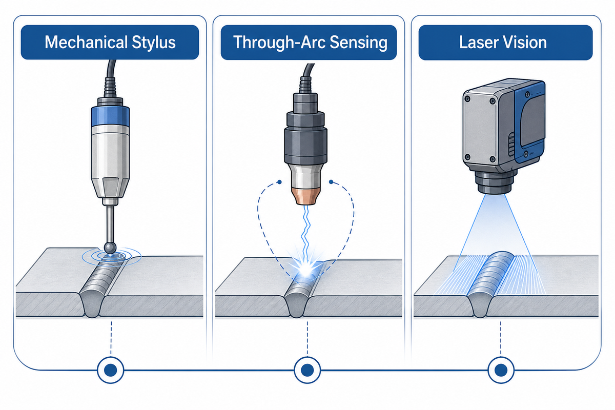
A rotating pipe rarely holds a perfectly true circle, so the torch needs a way to follow the joint as ovality, mill tolerance, and fixturing drift move the seam slightly out of the machine’s programmed path. Mechanical stylus followers cost the least and need the most physical maintenance; through-arc voltage sensing needs no extra hardware but reacts more slowly to sudden position changes; laser vision systems track fastest and most precisely but cost the most and need periodic lens cleaning and recalibration.
| Method | Typical accuracy | Relative cost | Surface tolerance | Maintenance | Best-fit OD range |
|---|---|---|---|---|---|
| Mechanical stylus / contact wheel | Moderate | Low | Needs a clean, unobstructed groove | High — wear parts contact the joint | 200–1,500 mm |
| Through-arc voltage sensing (AVC) | Moderate | Low to moderate | Requires stable arc, tolerates scale | Low — no added contact hardware | All ranges |
| Inductive proximity sensor | Moderate | Low to moderate | Needs consistent metal-to-sensor gap | Moderate | 200–1,000 mm |
| Ultrasonic seam sensor | Moderate | Moderate | Tolerates scale and moderate spatter | Moderate | 300–2,000 mm |
| Tactile finger / roller follower | Moderate to high | Low | Needs an accessible groove edge | High — wear parts | 200–1,500 mm |
| Camera-based arc-light sensor | High | Moderate to high | Sensitive to spatter and glare | Moderate — lens cleaning | 300–3,000 mm |
| Laser vision, single-line triangulation | High | High | Tolerates scale, sensitive to reflective surfaces | Moderate — lens cleaning & recalibration | All ranges |
| Laser vision, structured-light / 3D | Highest | Highest | Best tolerance of surface variation | Moderate — periodic recalibration | All ranges |
| Hybrid AVC + laser vision | Highest | Highest | Combines both methods’ tolerance | Highest complexity | All ranges, favored on high-value joints |
Laser-guided seam tracking on rotating joints isn’t a new idea: patent filings for laser-based arc-following systems on pipe and vessel welds date back decades (see GB9300403D0). Confidence in laser-vision tracking accuracy has grown since. Newer evidence backs this up: a 2026 peer-reviewed review of automated seam-tracking sensors, published in Sensors, confirms that triangulation-based laser vision remains the accuracy benchmark for modern robotic and manipulator-based pipe welding cells, while through-arc sensing stays the lower-cost default for less demanding joints.
Automated seam-tracking adoption on pipe and vessel welds has moved from a specialty option to a standard line item on new fabrication equipment, driven as much by first-pass quality pressure as by labor availability.
None of this is brand-specific: the comparison above is vendor-neutral because the right method depends on pipe surface condition, joint value, and budget, not on any single manufacturer’s marketing.
5. Which Code Governs Your Pipe Weld: API 1104, ASME B31, or a Pressure-Vessel Code?
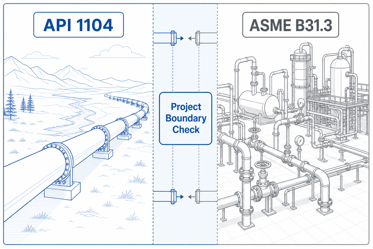
API 1104 generally governs cross-country pipeline girth welds, while ASME B31.3 typically applies to in-plant process piping, and the boundary isn’t always a bright line: some projects invoke both, depending on jurisdiction and whether the pipe crosses a regulated transmission boundary. This is a different code family from the AWS D1.1 structural code covered in our general manipulator guide, and qualifying to the wrong code can invalidate an otherwise sound weld.
| Code | Generally governs | Typical application |
|---|---|---|
| API 1104 | Pipeline girth welds | Cross-country transmission pipelines, oil & gas gathering lines |
| ASME B31.3 | Process piping | Refinery, chemical plant, and processing-facility piping |
| ASME B31.1 | Power piping | Boiler external piping and power-generation systems |
| ASME BPVC Section IX | Welder & procedure qualification | Referenced alongside B31 and pressure-vessel work generally |
| AWS D10 series | Recommended practice for pipe welding | Complements, does not replace, API/ASME requirements |
Federal pipeline safety rulemaking and state utility commission filings both reference these consensus codes rather than writing welding requirements from scratch, which is a useful sanity check when a contract specification cites a code by name: the base requirement is usually one of the entries above, with owner-specific additions layered on top.
How does a sub-arc manipulator differ from a traditional pipe welding manipulator?
Sub-arc (SAW) manipulators carry a heavier head with a flux hopper and flux-recovery system, so the boom and column need higher load capacity than a comparable GMAW-only machine. Wire feed and flux delivery also need to stay synced with travel speed, since SAW runs faster and tolerates less variation before bead shape suffers. A traditional GMAW-only manipulator carries a lighter torch, needs no flux system, and generally allows a lower-capacity boom for the same pipe OD.
6. Installing and Commissioning a Pipe Welding Manipulator
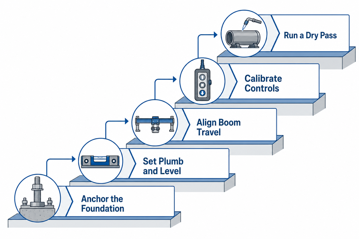
Five commissioning stages separate a manipulator delivery from a production-ready cell, and skipping any of them tends to surface as a problem during the first real production run rather than during setup, when it’s far more expensive to fix.
- Anchor the foundation. Confirm floor loading and anchor-bolt pattern match the column base before the machine ever arrives, since retrofitting a foundation after delivery adds weeks.
- Set column plumb and level. Check the column with a precision level in both axes; a column that is out of plumb compounds into boom-tip error over a long stroke.
- Align boom travel. Run the boom through its full stroke and confirm travel stays parallel to the intended pipe centerline, adjusting rail or track alignment before any welding.
- Calibrate the control system. Set travel-speed limits, oscillation parameters, and any seam-tracking sensor zero-points against a known reference joint, the same procedure-qualification logic ASME BPVC Section IX requires for welder and procedure qualification more broadly.
- Run a dry-run pass. Cycle the full sequence with the torch off, on a real or mock pipe, before ever striking an arc under power.
Adding a fully integrated, CNC-style control panel with a user-friendly interface and variable speed settings can simplify this sequence, but it still depends on a load-bearing foundation and a properly calibrated servo drive underneath.
7. Running a Pipe Welding Manipulator: Setup Sequence and the Errors That Ruin a Pass
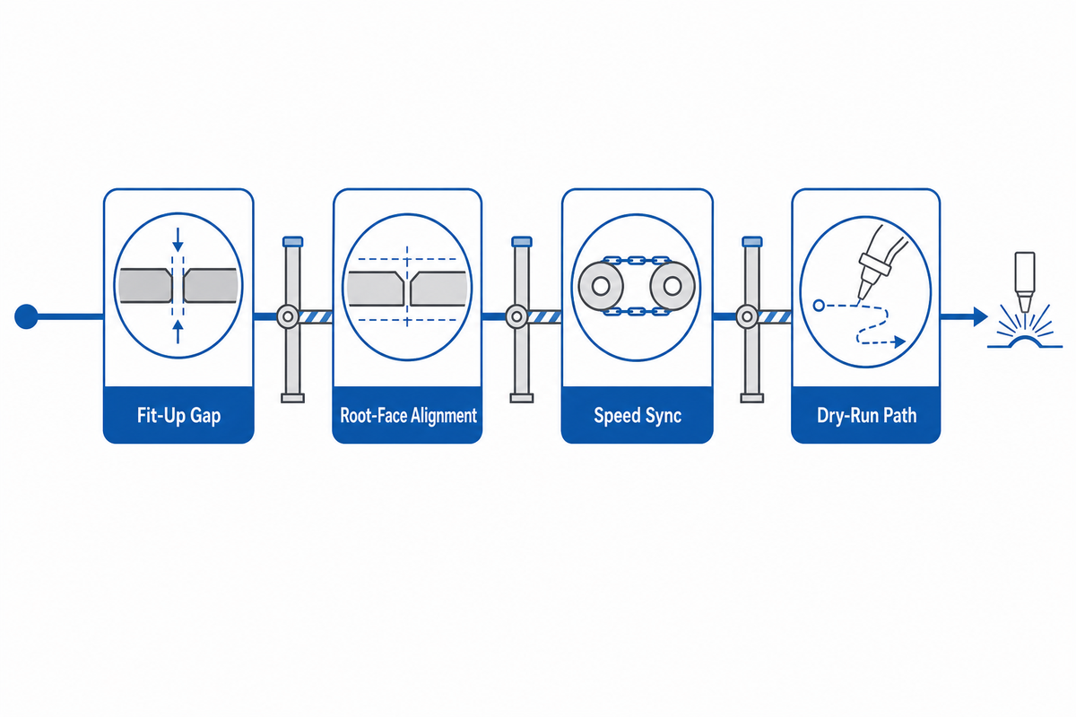
Run the sequence out of order and the first pass usually shows it, most often as an inconsistent bead width or a start-of-pass defect that traces straight back to a skipped setup step. Following a fixed sequence, consistent with AWS D10 recommended practice for pipe welding, helps avoid this: confirm fit-up and root gap, secure the pipe in its fixture or rotator, position the torch and set stickout, set travel speed and oscillation to the qualified procedure, run a short dry-run segment, then commit to the full pass.
Use the 4 Signal Pipe Fit Readiness Check
Before striking an arc, confirm fit-up gap tolerance, root-face alignment, rotator-and-manipulator speed-sync, and a clear pass-1 dry-run path, four signals that catch most avoidable first-pass defects before they happen.
These four signals catch the errors that most often ruin an otherwise well-programmed pass:
Workflow stability depends on precise speed control, steady torch movement, and welding speed matched to the qualified procedure rather than to habit. It also depends on operator comfort: wireless pendant ergonomics let a technician stay in one position near the joint instead of walking the full boom length to make adjustments.
Do
- Check fit-up gap and root alignment against the WPS before every new spool.
- Confirm rotator and manipulator speeds are synchronized before a compound-seam pass.
- Run a torch-off dry pass whenever the fixture or pipe size changes.
- Re-zero seam-tracking sensors after any collision or hard stop.
Don’t
- Assume the last job’s travel speed still fits a different wall thickness.
- Start a circumferential pass before confirming rotator torque against pipe self-weight.
- Skip the dry-run pass to save time on a familiar-looking job.
- Leave a seam-tracking sensor uncalibrated after a fixture change.
8. Safety Around a Rotating Pipe and a Powered Boom
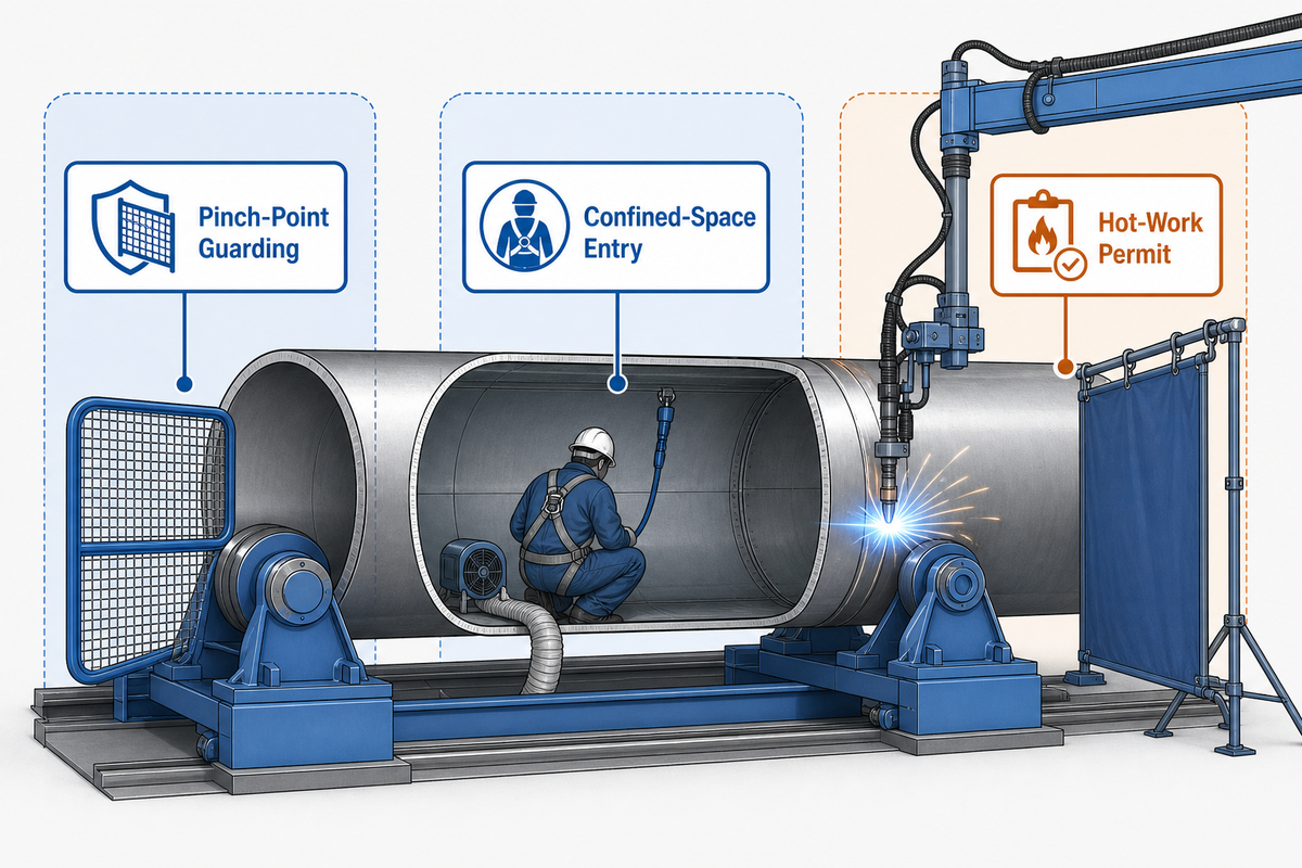
Two OSHA standards apply the moment a technician sets up a pipe manipulator-and-rotator cell: 29 CFR 1910.212 covers general guarding on rotating and traveling machine parts, and 29 CFR 1910.146 adds permit-required confined-space requirements the moment anyone needs to enter a large-bore pipe’s interior for fit-up, inspection, or root-pass access.
- Large-bore pipe interiors can qualify as a permit-required confined space under 29 CFR 1910.146, requiring atmospheric testing, ventilation, and an attendant before entry.
- Synchronized rotation under boom-mounted tooling creates crush and pinch-point hazards distinct from a static fixture, especially during speed changes.
- Welding inside or adjacent to a confined pipe section typically also triggers a separate hot-work permit process on top of confined-space entry rules.
These requirements sit on top of, not instead of, the general machine-guarding practices already covered for column-and-boom equipment broadly in our general manipulator guide; a pipe cell simply adds the confined-space and pipe-interior-entry layer on top of standard guarding.
9. Pairing a Manipulator With a Pipe Rotator: Making Both Machines Track Together
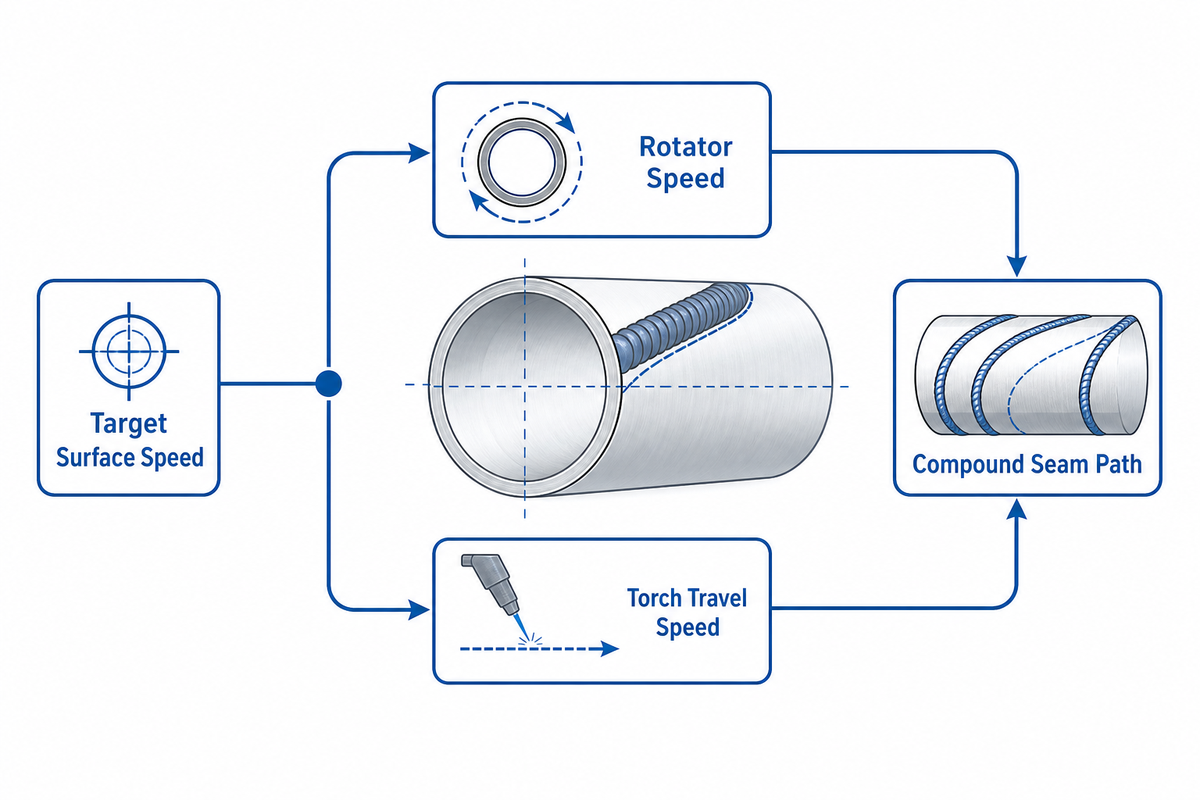
When the pipe rotates and the torch travels at the same time on a compound or spiral seam, the two motions have to agree on a single combined travel speed, or the weld bead spirals at the wrong pitch. The rotator’s rotational speed and the manipulator’s linear travel speed both have to be set from the same target surface speed, converted through the pipe’s own circumference.
Illustrative example: take a 610 mm (24-inch) OD pipe with a target linear travel speed of 300 mm/min at the joint. Circumference works out to π × 610 mm ≈ 1,916 mm. Dividing the target travel speed by that circumference gives the rotator speed needed to match it: 300 ÷ 1,916 ≈ 0.157 rpm. If the rotator turns faster or slower than that without the manipulator’s travel speed changing to match, the effective bead pitch drifts off the intended seam path, which is exactly why synchronization, not just individual machine capability, is the real engineering problem in a paired cell.
Aubrik’s own manipulator-and-rotator pairing follows this same synchronization logic in practice: the SAW/GMAW dual-head ABOKE FWM series pairs with Aubrik’s pipe rotator line so travel and rotation speeds can be set from a shared control reference rather than tuned independently by trial and error.
What is the role of positioning equipment in pipe welding?
Positioning equipment in a paired pipe-welding cell splits into two distinct jobs. Rotators or turning rolls carry the pipe’s own rotation, holding a steady circumferential speed independent of the welding head. The manipulator, separately, positions and travels the torch along the boom. Neither substitutes for the other: a rotator alone still needs a stationary torch mount, and a manipulator alone can’t complete a girth seam without manually indexing the pipe between passes.
Some shops also keep a dedicated pipe welding positioner on hand for flange or end-cap work where continuous welding around a full circumference isn’t required, though a rotator remains the standard choice for pure pipe rotation.
Key takeaway
A manipulator and a rotator solve two different halves of a pipe weld, and matching their speeds through the pipe’s circumference, not just matching their individual capacities, is what keeps a compound seam on path.
10. Maintenance and Troubleshooting: Keeping Pipe Welds Consistent Pass After Pass
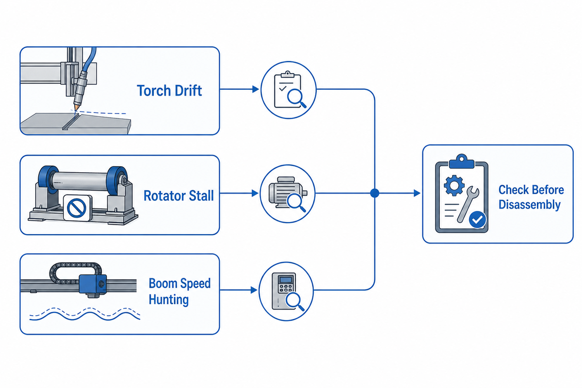
A drifting torch and a stalling rotator look similar from across the shop floor, but the underlying causes differ enough that guessing wastes a shift. The fault-to-cause table below narrows the search before a technician starts disassembling anything.
| Fault indicator | Likely cause | First check |
|---|---|---|
| Torch drifts off the seam mid-pass | Seam-tracking sensor drift or mounting play | Re-zero the sensor; check mounting hardware for play |
| Inconsistent bead width along one pass | Travel-speed hunting or worn drive components | Log actual travel speed against set point over a full pass |
| Rotator stalls under load | Torque headroom too tight for pipe weight | Recheck pipe weight against rotator torque rating |
| Speed hunting or surging on the boom | Worn drive belt/gearing or control tuning drift | Inspect drive train; re-run control calibration |
| Alignment loss over repeated jobs | Column or rail settling, foundation shift | Re-check plumb/level against original commissioning record |
Most of these operating faults trace back to the same five commissioning checks from H2-6 quietly drifting out of tolerance over time, which is why a scheduled recheck of plumb, alignment, and calibration, not just a reactive fix, keeps weld quality consistent pass after pass, echoing the periodic-recalibration finding in the 2026 seam-tracking sensor review cited above.
Left unresolved, any of these faults erodes repeatability and adds downtime that a shop rarely plans for.
11. Why Pipe Welding Automation Adoption Is Accelerating in 2026
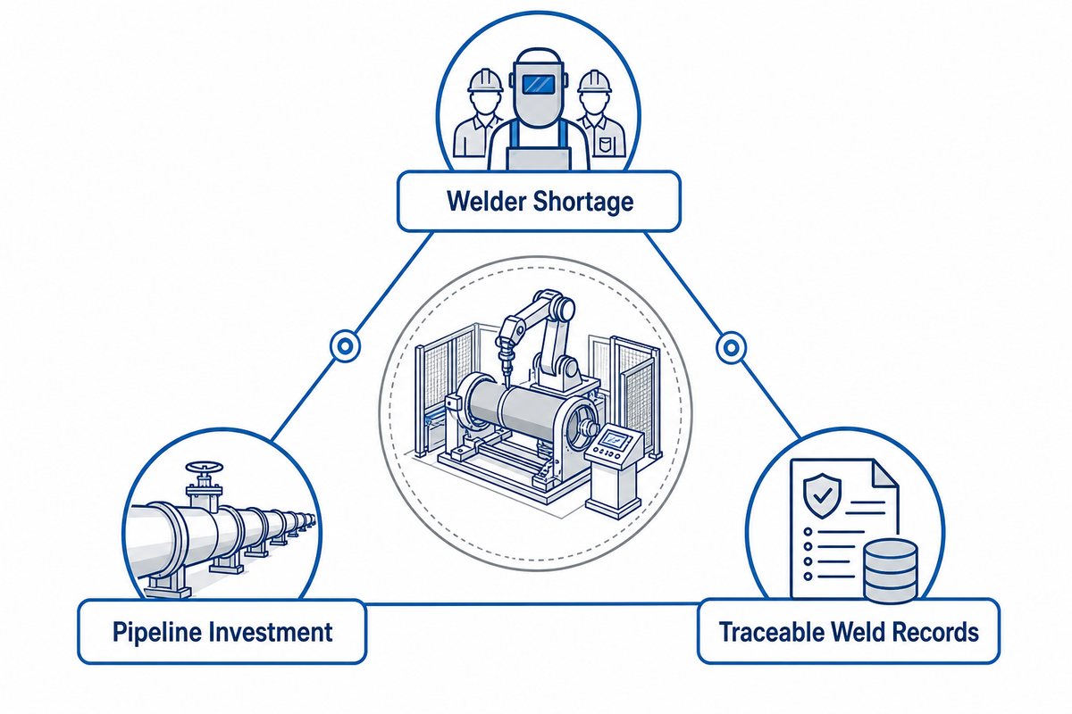
Three forces are pushing pipe welding automation forward in 2026, and market size is the smallest of them. Persistent shortages of qualified pipe welders are pushing shops toward manipulator-and-rotator cells that let one operator run work a manual crew previously needed several welders to cover. Continued investment in oil, gas, and water-pipeline infrastructure is expanding the pool of large-diameter pipe fabrication work that automated cells handle more consistently than manual welding. Industry 4.0-style documentation requirements, traceable weld parameters, procedure records, and quality data per pass, are also easier to satisfy with a controlled, repeatable machine cycle than with manual technique alone. Across the welding industry, pipeline construction and other large-diameter fabrication work is shifting toward automated welding for exactly these reasons, and welding operations data reflects it.
That market data reflects those drivers rather than driving them on its own: the automatic pipe welding machines market is estimated at roughly USD 2.87 billion in 2025 (Spherical Insights), projected to reach approximately USD 5.91 billion by 2035, a 7.49% compound annual growth rate (Persistence Market Research). That figure is background context for why more shops are asking the sizing and seam-tracking questions covered earlier in this guide, not the reason to buy any particular machine.
Frequently Asked Questions
What is a pipe welding manipulator?
Shops use one to carry a SAW or GMAW torch head automatically along a pipe joint, holding travel speed, torch angle, and arc position steady across the pass instead of relying on a welder to track the seam by hand. On circumferential seams it is typically paired with a rotator that turns the pipe itself, while on longitudinal seams the manipulator’s own boom travel does the work alone, covering pipe from small-bore spools up to large-diameter vessel and pipeline sections.
What types of pipe welding manipulators are there?
Pipe welding manipulators are generally grouped by duty class rather than a single universal type: mini units cover roughly 50–300 mm pipe OD, while heavy-duty machines reach 1,000–3,000 mm. Within each class, machines vary by process capability (single-head GMAW, single-head SAW, or dual-head), boom and column stroke, and whether the machine is sold as a standalone manipulator or as a pre-matched pairing with a rotator for circumferential work.
How does a column and boom welding manipulator work?
A column and boom manipulator uses a vertical column to set welding-head height and a horizontal boom to carry the torch along its travel path, with drive motors controlling both axes plus torch travel speed during the weld. The column can also rotate on some models to reposition the boom around a fixed workpiece. For the full mechanism breakdown beyond pipe-specific use, see our general column and boom manipulator guide.
Can a welding station be integrated with a pipe welding manipulator?
Yes. Pipe welding manipulators are typically installed as one station within a larger welding cell, integrated with a rotator or turning rolls, fume extraction, and a control system that coordinates all of the equipment from a shared operator interface.
What advantages do wireless controls offer in a welding manipulator?
Wireless pendant controls let an operator reposition around the pipe and fixture without a tethered cable catching on tooling, which matters most on larger-diameter cells where the operator needs to walk the full boom length during setup and monitoring.
What are the benefits of using a boom welding manipulator?
A boom manipulator holds consistent travel speed and torch angle across a full pass, reducing the bead-quality variation that comes from manual torch handling, while freeing a welder to run other work during long automated passes.
What is a welding positioner, and how does it relate to a pipe welding manipulator?
A welding positioner tilts and rotates a workpiece to present a joint at a favorable welding angle, which is a related but distinct job from a pipe rotator, which simply turns the pipe at a controlled speed for a manipulator’s torch to follow.
What welding processes can a manipulator system accommodate?
Most pipe welding manipulators accommodate SAW and GMAW as standard, consistent with AWS D10 recommended practice for pipe welding, with dual-head models running both processes on the same boom for jobs that need a root pass in one process and fill/cap passes in another.
Ready to Size a Cell for Your Pipe Work?
Compare Aubrik’s ABOKE FWM manipulator range and matched rotator line against your own pipe OD, wall thickness, and duty-class requirements.
How We Sourced This Guide
The source base for this guide includes Aubrik’s first-party product data, including the ABOKE FWM duty-class specifications and the SGS-MEX-2024-0789 pipe-spool case study, alongside public standards (API, AWS, ASME), OSHA regulatory text, a granted seam-tracking patent, a 2026 peer-reviewed sensor study, and published market-sizing research. Duty-class and case-study figures reflect Aubrik’s own equipment; sizing guidance for other manufacturers’ machines reflects general engineering practice, not a claim about their products.
References & Sources
- API 1104, Welding of Pipelines and Related Facilities, American Petroleum Institute
- AWS D10 Series, Recommended Practices for Pipe Welding, American Welding Society
- ASME B31.3 Process Piping, ASME
- 29 CFR 1910.146, Permit-Required Confined Spaces, OSHA
- Federal Register, Pipeline Safety Regulation
- South Dakota Public Utilities Commission, Pipeline Welding Compliance Filings
- GB9300403D0, Laser-Guided Arc-Following Patent, Google Patents
- Automated Seam-Tracking Sensor Review (2026), Sensors, MDPI
- Trade Reporting on Seam-Tracking Automation, The Fabricator
- Automatic Pipe Welding Machines Market Report, Spherical Insights
- Automatic Pipe Welding Machines Market Forecast, Persistence Market Research