Get in Touch with Aubrik Company

Choosing a Large Welding Positioner for Oversize Weldments

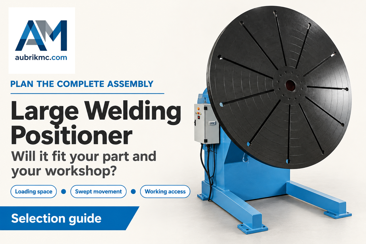
A large welding positioner holds and moves an oversize weldment to position its joints within reach. It’s selected by the complete part-and-fixture envelope, the permitted load at its center of gravity and the route used to load it. A table can carry the weight yet leave a clamp too close to the floor.
Beginning support with a headstock-tailstock arrangement is a good choice for long frames. If a vessel is round and has an appropriate surface for rolling, consider the use of turning rolls. A tilt-turn table is a good choice to provide both rotation and a change of weld angle. Positioning a joint in the flat position can reduce awkward reaching during manual welding.
Large welding positioner sizing starts with two envelopes
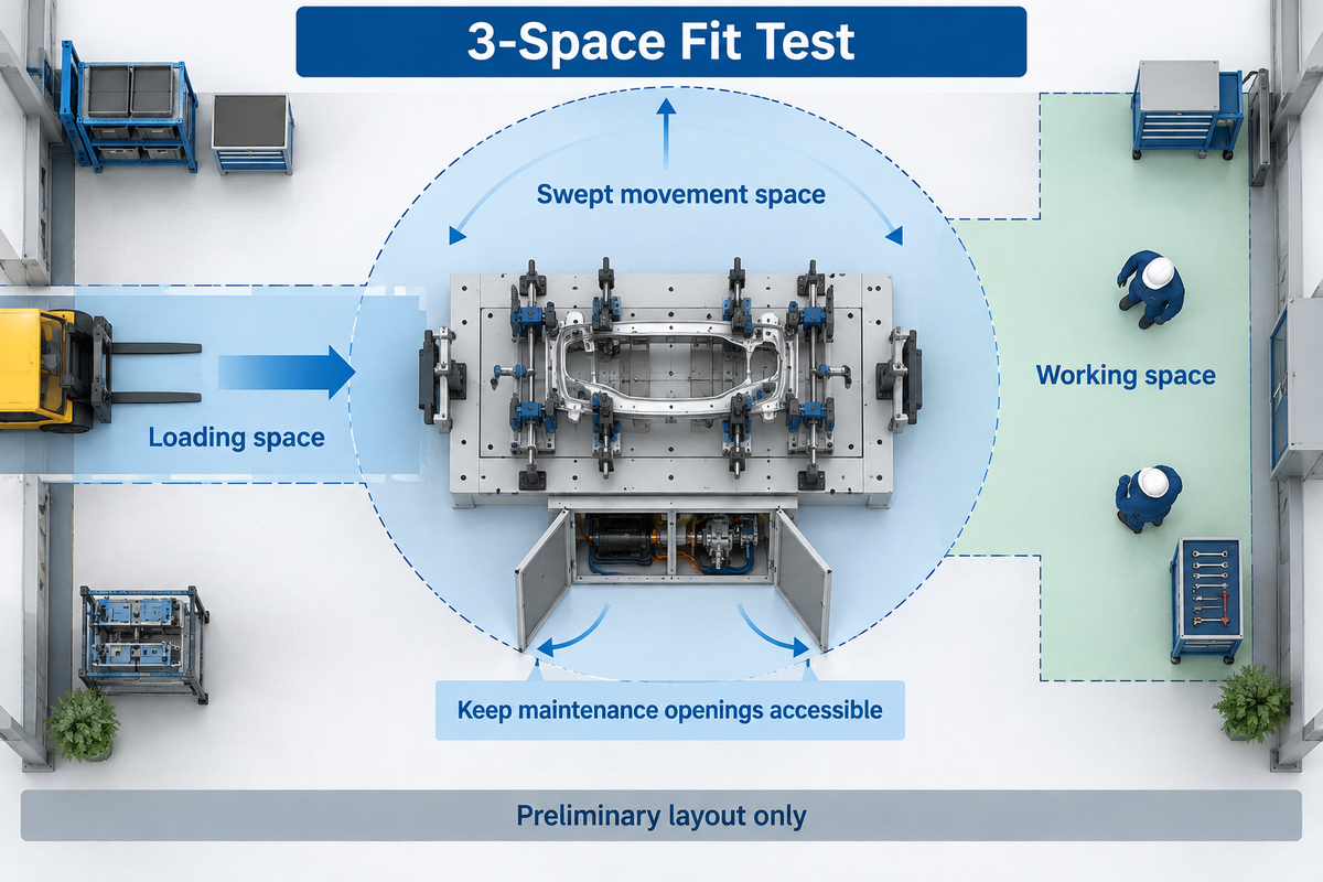
Everything that’s moved has a load envelope and a geometric envelope. Collisions are prevented by the geometric limits, and the load limits account for the weight, center of gravity and motion. A broad, balanced frame can have a large swing radius while its mass is close to the rotation axis. Writing in AWS Welding Digest, Koike’s Ron Krasnek explains why weight, size and center of gravity belong in lifting and positioning plans.
Moving a long sofa through a doorway provides a good illustration of fitting something into a space while still determining if it can clear an obstacle in the path. Likewise, a fabrication shop must determine the limits of its installed workpiece as well as the limits of the path used for loading. Crane access, staging space and the doorway matter before the first weld. Include the heaviest assembly and the widest one when they are different parts.
The 3-Space Fit Test is a preliminary layout check: draw the loading space, the swept movement space, and the working space on the same plan. The working space illustration must show the maintenance access openings. Use the drawings to compare alternative layouts. The machine supplier and site engineering team will determine the allowable loads and the required safety measures.
| Input or check | Example entry | What it changes / owner |
|---|---|---|
| Part length | 4.0 m, assumed | Crane approach and staging; plant manager |
| Complete rotating width | 1.6 m, assumed | Include clamp projections; fixture designer |
| Complete rotating height | 0.8 m, assumed | Include fixture below the part; fixture designer |
| Axis location | Centered in that cross-section | Required premise for the diagonal calculation; engineer |
| Farthest corner radius | 0.894 m, calculated | Compare against obstacles through rotation; engineer |
| Geometric floor gap | 0.10 m, assumed | Arithmetic input only, not a personnel clearance; engineer |
| Axis height for that gap | 0.994 m, calculated | Dimension to axis, not machine overall height; supplier |
| Loading path | Part enters from the aisle side | Keep lifting gear clear of controls; lifting planner |
| Working space | Torch and extraction arm reach both faces | Reserve access outside the sweep; welding and safety teams |
Longer tables and bigger bases won’t remedy blocked entrances. If the proposed layout requires removing a guard whenever a part arrives, revise the loading arrangement with the supplier before ordering.
Swing clearance: measure the whole rotating assembly
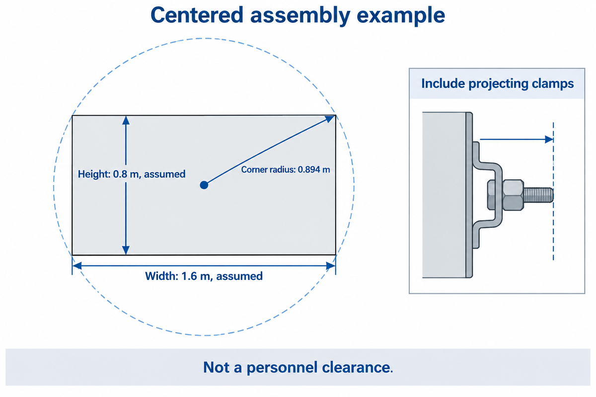
For the centered rectangular assembly in the layout example, the farthest corner is situated about ½ diagonal from the center. Width alone doesn’t account for that corner during rotation. Measure the full fixture, including clamps and locating pins, then trace its path past the floor, machine frame and nearby equipment through every intended orientation.
Halving the example width and height gives 0.8 m and 0.4 m. Squaring each of these values, adding the results and taking the square root gives the radius as 0.894 m. Adding the assumed geometric gap gives the axis height shown in the table. Off center axes, projecting brackets, and tilted rotation planes need their own swept path analysis.
Bill Morgan, then an engineering manager at Bluco, wrote about fixture balance and swing diameter in Don’t Forget the Fixturing. Lowering the fixture can bring the center of gravity nearer the axis while pushing an outside edge beyond the available swing. But, in some cases, clashes can be resolved by changing the fixture shape.
“The positioner must support the weight of both the part(s) and the fixture.”
Think of a frame whose underside clamps clear the floor when positioned upright. About halfway through a turn, a clamp handle becomes the lowest point. Both shortening and relocating the handle change the swept envelope; however, lifting the entire machine changes the loading height and foundation arrangement. Compare both changes on the drawing before selecting an elevating base.
Floor clearance is just one of operator safety’s issues. The example gap isn’t the right to stand next to a rotating weldment. Guarding and hot-work controls require a separate assessment of the actual workstation.
Tilt-turn, headstock-tailstock or turning rolls?
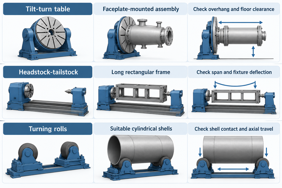
Match positioning equipment to the surfaces available for support. A tilt-turn table can support an assembly mounted on its faceplate. A headstock-tailstock system can also support a fixture in between the two ends. Turning rolls support suitable cylindrical shells on their outside surface. Length, overhang and access to the weld determine which arrangement fits the job.
Equipment families in Welcome to the World of Positioneering use a number of various support and movement configurations. Its author, Koike product manager Don Burgart, also emphasizes the part dimensions and the welder’s access. The following applies the distinctions described to common fabrication tasks.
| Work or movement needed | Arrangement to consider | Hidden bottleneck |
|---|---|---|
| Short assembly needing tilt and rotation | Fixed-height tilt-turn positioner | Overhang and floor clearance at full tilt |
| Tall fixture needing a different working height | Elevating positioner | Raised load envelope and loading height |
| Long rectangular frame | Headstock-tailstock fixture | Support span and fixture deflection |
| Cylindrical vessel with suitable contact bands | Turning rolls | Shell contact, projections and axial travel |
| Flat assembly needing horizontal indexing | Horizontal turntable | No tilt to expose underside joints |
| Pipe flange or short spool | Chuck or faceplate positioner | Clamp interference at the joint |
| Light parts repositioned by hand | Manual balanced fixture | Balance changes as parts are added |
| Repeated circumferential seam | Powered table with torch support | Loaded low-speed smoothness |
| Programmed welds on several faces | Robot-integrated positioner | Coordinated axes, cable routing and cell access |
Vessels with brackets in the roller contact path need different support than a smooth shell. Our guide to turning rolls for cylindrical work discusses this in detail. A rotator cannot grip an irregular frame merely because its advertised tonnage is high enough.
For a long weldment, include the fixture between the headstock and tailstock in the layout. End support can open access along the sides but the fixture can block the root of a joint. Pretacking selected subassemblies may simplify the later fixture, as long as the welding sequence allows it.
Load capacity: include fixtures and center of gravity
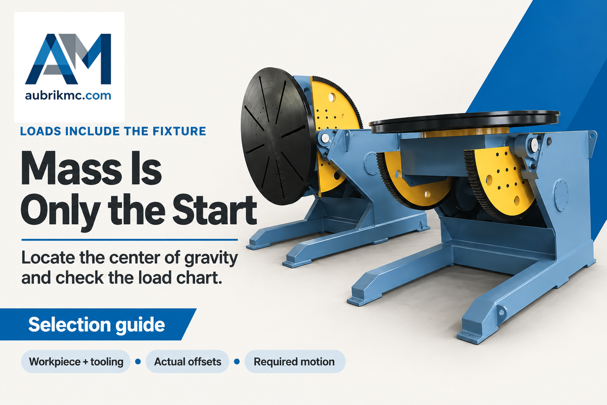
When checking load capacity, use the combined workpiece and tooling mass, and locate the assembly’s center of gravity relative to the machine axes. The permitted load depends on the manufacturer’s stated conditions. Increasing the size of the table diameter doesn’t increase the permitted torque, and a nominal weight label doesn’t apply to every tilt angle.
Take an assumed 4,200 kg weldment on a 600 kg fixture with 100 kg of clamps. The mounted mass is 4,900 kg. A machine advertised at 5,000 kg is therefore a candidate for a load-chart check, not an approved selection. The position of that mass and the required motion determine if the arrangement is permitted.
Where is the center of gravity after fixturing?
The position of the combined CG shifts toward the added fixture, clamps, and heavier portions of the weldment. Locate each component’s mass and position in a shared coordinate system, then calculate the combined center. Recalculate after adding a subassembly that changes the mass distribution. Compare the results of the analysis to the supplier’s load chart. Keep in mind the supplier’s reference axes.
A frame that’s geometrically wide can be balanced about its rotation axis. A compact casting mounted far from a tilt axis can create a substantial moment. Increasing swing clearance may solve the first problem; a different machine or fixture may solve the second. Neither is solved by comparing kilograms alone.
The deeper distinctions between rotation torque and tilt moments are addressed in the heavy-duty welding positioner load guide. Keep fixture mass and actual offsets on any model proposed. If a supplier gives you a bigger motor without addressing the stated load case, the selection is incomplete.
Rotation speed, weld access and fixture design
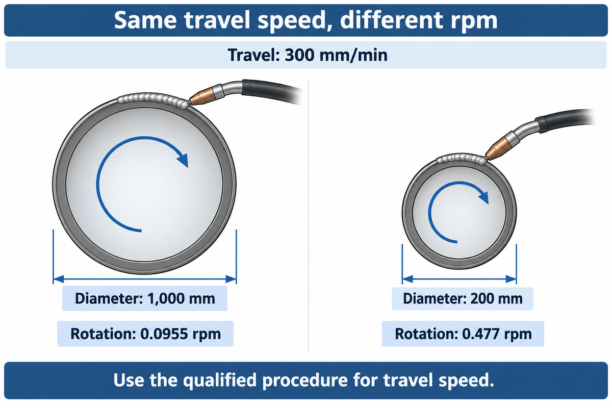
Match rotation speed to the seam diameter and the travel speed required by the welding procedure. When a large circumference passes a stationary torch, slow, smooth rotation matters. Maximum rpm alone doesn’t define the capability for that duty. Fixture access, current return and the ability to start steadily under load also affect the usable welding system.
Considering a seam of 1,000 mm diameter and a travel speed of 300 mm/min, rpm = 300 ÷ (π × 1,000) = 0.0955. With the same travel speed, a seam of 200 mm diameter requires about 0.477 rpm. The required rotation changes with diameter; the qualified procedure gives the travel speed.
Variable speed rotation requires enough usable range for both parts. Controlled movement during the first fraction of a turn matters as much as steady rotation after the drive settles. Specify a loaded demonstration near the required low speed, including starts, stops and reversal.
Welding small parts illustrates the opposite speed limit. A benchtop positioner listed at 0-5 rpm may suit its own work range while providing no help for a multi-ton load case. Compact positioners also leave less room around a large flange. Keep the workholding and access requirements associated with each machine comparison.
Can I use a welding positioner with MIG, Stick, and TIG welding?
Yes, an appropriate positioner can support MIG, stick and TIG work, if its welding-current path, workholding and motion suit the welding process. Powered rotation can improve weld quality by aiding the operator in attaining the intended travel and weld angle. It doesn’t replace joint preparation, shielding or the applicable welding procedure.
On pipe flanges for MIG and TIG welding, allow clearance for the torch body, filler access, and the extraction arm. The clamp that holds the flange may still prevent the welder from achieving the full joint. The pipe welding positioner setup guide addresses this workholding issue.
According to OSHA 29 CFR 1910.254, if a fixture is regularly used as a welding-current return, it must be suitably bonded or include a current collecting device. Lifting chains and cranes must not be part of the return circuit. A correct current path protects the intended welding arrangement; a nominal load rating says nothing about it.
In semi-automated welding, the operator controls fit-up and checks the bead. A repeatable fixture places the joint in a consistent position. Smooth rotation supports a consistent bead. If changing clamps takes longer than welding, increasing drive speed will not remove that throughput constraint. Reducing repeated manual handling can free station time; however, loading and unloading still require a suitable lifting arrangement.
Large welding positioner cost: compare the installed package
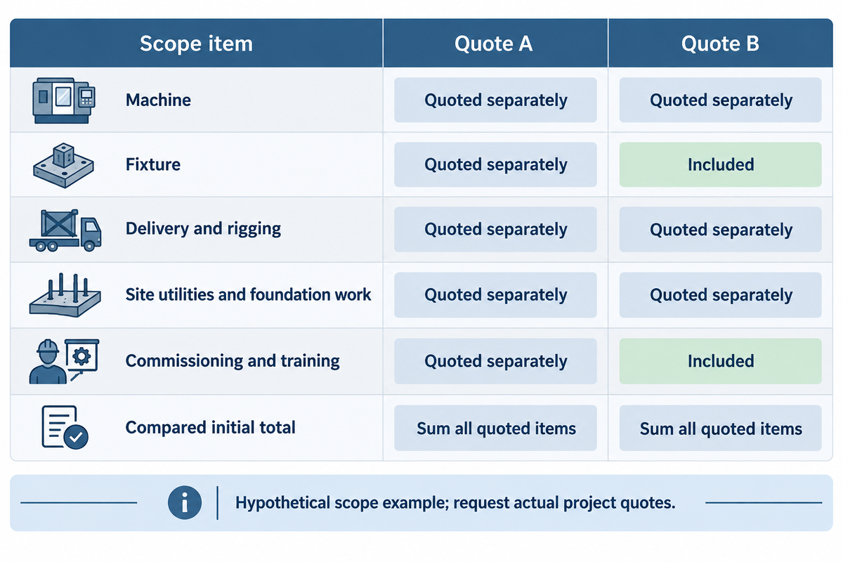
Large welding positioner cost requires a project quote that includes the machine, fixture, delivery, site work and commissioning. Compare these items on the same installed scope, then consider maintenance and energy costs separately. The example shows two possible scope combinations; it doesn’t provide market costs and makes no claim for payback.
| Scope item | Quote A | Quote B |
|---|---|---|
| Machine | Quoted separately | Quoted separately |
| Fixture | Quoted separately | Included |
| Delivery and rigging | Quoted separately | Quoted separately |
| Site utilities and foundation work | Quoted separately | Quoted separately |
| Commissioning and training | Quoted separately | Included |
| Compared initial total | Sum all quoted items | Sum all quoted items |
This scope example requires a separate price for each fixture and commissioning for Quote A to be compared to Quote B. Add any excluded guarding, extraction, taxes or robot integration to either offer before using its total as a project budget. For fixed-location machines, OSHA’s anchoring requirement also belongs in the site-work discussion: machines designed for a fixed location must be securely anchored to prevent walking or moving.
A plant manager may favor the fixture that shortens changeovers; finance needs the hours and costs behind that choice. Finance, however, needs to understand the cost and the time required to make that improvement. Assume a measured improvement later proves to save 15 minutes per completed part at 8 parts per shift: that releases 2 hours of station time. It doesn’t automatically remove 2 paid labor hours or create sales for another two hours of production.
Put these items on the quotation request
- Largest mounted part, fixture mass, center of gravity and required orientations.
- Loading drawing, complete swept envelope and working-access layout.
- Loaded speed range, workholding and rated welding-current path.
- Responsibility for guarding, utilities, foundation, extraction and integration.
- Representative-part acceptance, training, spares and service scope.
Used welding equipment needs its own allowance for inspection, repairs and controls compatibility. Compare it to new equipment only after these items and current load documentation are included. A low purchase price can otherwise conceal work that the workshop must fund separately. For mixed shop work, include fixture-change time for the actual batch mix and then assess labor saving.
Manufacturer capacity claims: compare the same load basis
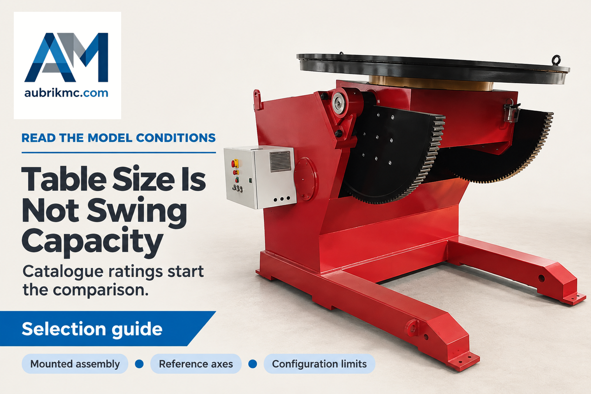
Aubrik’s heavy-duty catalogue lists HB5000, HB10T and HB20T models at 5,000 kg, 10,000 kg and 20,000 kg respectively. The model entries help shortlist table size and motion. Final selection uses the mounted load and its offsets, together with the supplier’s configuration-specific limits, rather than the largest advertised capacity in a product family.
| Model | Listed load | Table diameter | Rotation range | Listed tilt |
|---|---|---|---|---|
| HB5000 | 5,000 kg | 1,600 mm | 0.05–0.5 rpm | 0–90° |
| HB10T | 10,000 kg | 2,000 mm | 0.05–0.3 rpm | 0–90° |
| HB20T | 20,000 kg | 2,500 mm | 0.05–0.2 rpm | 0–90° |
Refer to the model table given in Aubrik Heavy-Duty positioner specifications for the mentioned ranges. A table diameter measures the mounting face, and it isn’t the maximum permissible swing diameter. The overall height of the machine is different from the height of the rotation-axis used for layout calculation.
Compare rated load in the same units. A quotation in tons needs to mention if it means metric tons or short tons, before any comparisons in kilograms. Differentiate a standard model from a custom capacity claim. Neither a robot-ready label nor a programmable control establishes coordinated-axis performance for the proposed cell.
For other products in the family, compare welding positioners by support arrangement. A high-quality positioner for one fixture may not be suitable for another with the same mass but a different overhang. The purchase specification should name the actual assembly and load case.
Installation space, guarding and maintenance
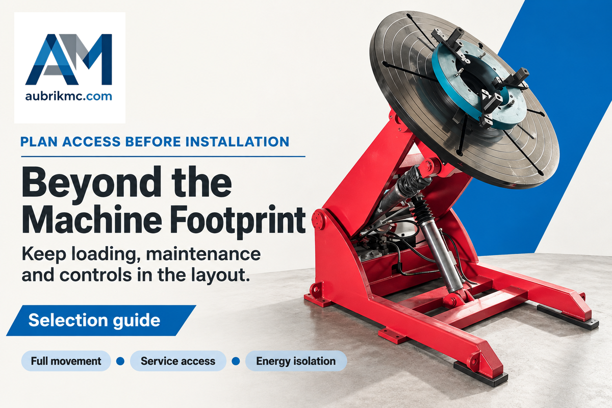
Before placing the machine, ensure space is reserved for loading and full movement, and for access by personnel for maintenance and welding. Add the site’s guarding and hot-work controls to the layout. Fixed equipment must be secured, and access for servicing must be provided to allow energy to be isolated. A machine footprint doesn’t include the area occupied by a part that’s rotating, or by personnel who work in the area around the rotating part.
OSHA 29 CFR 1910.212 addresses rotating-part and point-of-operation hazards, along with anchoring machines designed for a fixed location. A tall riser changes the installed arrangement; it is not a casual substitute for a properly sized base. Foundation design must also address the supplier’s loads and the actual floor.
Hot-work space is different from swing clearance. OSHA 29 CFR 1910.252 states that combustible material must be moved at least 35 feet (10.7 m) from the work site, if possible; otherwise, protective measures are required. Fire-watch and spark-travel conditions can also matter beyond that distance; it is not a universal safe boundary.
The same regulation describes movable local-exhaust hoods placed as near as practicable to the welding work. There must be clearance for the hood to be moved when the work is moved to a different location. An extraction arm trapped behind the fixture cannot follow the next joint.
Service requires more than an emergency stop. The definitions in OSHA 29 CFR 1910.147 state that a push-button or selector switch isn’t an energy-isolating device. Energy-control procedures must be developed by the employer for covered service (including maintenance) of equipment. Control of stored energy and verification of isolation by authorized personnel form part of covered servicing.
Verify the electrical supply against the ordered equipment including phase and frequency. A small 110V model does not establish supply requirements for heavy industrial equipment, nor does a catalogue reference to 220V establish compatibility with every shop. Ergonomics also affects the control location; the operator has to see the joint and reach the controls from the intended working position. Our positioner operating principles provide more detail on the operating context; equipment-specific instructions govern the installed unit.
Industry outlook: robot-cell integration standards
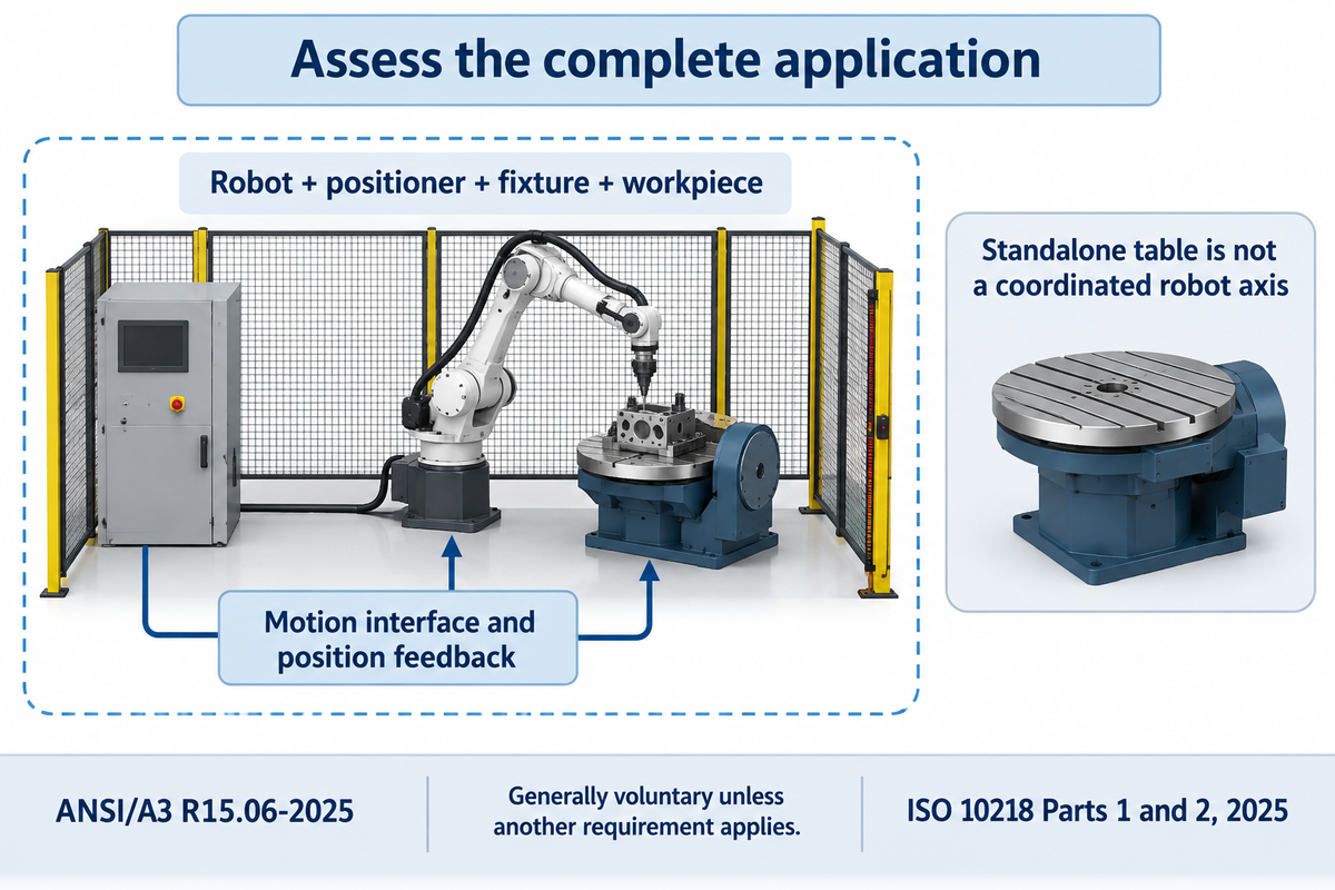
The 2025 robot-safety revisions mean the complete integration of a robot-cell becomes a central planning concern. A positioner, fixture and workpiece affect that application, in addition to the robot. For a purchase intended to support automation, agree the applicable standard editions and integration responsibilities before fixing the cell layout or ordering standalone controls.
In its September 2026 robot safety standards update, A3 explains that ANSI/A3 R15.06-2025 incorporates the 2025 ISO 10218 Parts 1 and 2. Part 3 addresses US user requirements. These are generally voluntary consensus standards unless referenced by regulation or another applicable requirement; their publication does not make every standalone positioner a robot cell.
Automated welding also requires consistent part presentation. A variable-speed welding positioner turntable used for manual welding isn’t, by itself, a coordinated external robot axis. Precise control requires the specified motion interface and position feedback with repeatability appropriate to the welding applications assigned to the cell.
For a future robot installation, reserve cable routes and access for fixture changes now. Analyze the complete cycle of the workflow and identify areas where improvements can be realized. Demonstrate that the work cell meets the defined safety, motion, and production requirements. The useful gain is completed acceptable work; a faster empty turntable does not establish how much industrial welding output the cell will deliver.
Frequently asked questions
Why can a heavy-duty welding positioner carry the load but lack swing clearance?
A heavy-duty welding positioner needs room to move the weldment and let the operator access the joint in every required welding position. Examples of loads include frames, flanges, and other fabricated assemblies. The table diameter measures its mounting face; the complete assembly and its projections determine the swept space. Suitability is determined by the overall mounted load, its center of gravity, required movement, available clearance, and the limits of the moving structure.
What is a benchtop welding positioner?
A benchtop welding positioner is a compact unit mounted on a bench or support, and is meant for use within its published limits of load and movement. An extremely large but lightweight part may exceed its turning clearance, while a very small but dense part may exceed its load rating. Both cases should be checked.
Do I include a 3-jaw chuck in the swing envelope for pipe or flange welding?
A three-jaw chuck used to hold round components adds its projections to the swing envelope; it isn’t enough to measure the pipe or flange alone. Other workholding methods may be preferable when their geometries leave better clearance around the component. Include the chosen workholding weight in capacity calculations and assess clamping security, weld access and distortion for the actual assembly.
Do I need forward tilt?
Forward tilt is useful when it puts the joint in a workable position without additional setups. The required angle is determined by the weld and the geometry of the fixture. Check clearance throughout the movement; a larger advertised tilt range does not guarantee better access.
Can a welding positioner fit a future robotic welding cell without changing the layout?
A positioner can work with a welding robot in a future cell if its layout reserves space for motion, controls, safeguarding and access. A standalone variable-speed table isn’t, by itself, a coordinated robot axis. The integrator must establish the required positioning accuracy, repeatability, communication, stopping behavior and cable routing. Also, fixtures need to present the joint consistently. Compare the proposed system on a representative weldment, including loading and unloading routes, before treating the present layout as suitable for a future robot cell. See if faster rotation or an extra axis results in greater production.
Do I need full rotation?
Full rotation is helpful if the weld or access sequence requires it. Some jobs require indexing between positions. Cable routing, hoses, fixtures and guarding must suit the planned motion; a table that turns through a circle does not permit unlimited continuous rotation.
What should I check about loading space before accepting a heavy-duty positioner?
Use the agreed representative part and fixture to check loading, mounting, permitted movements, weld access and unloading against the purchase specification. Compare actual motion and loaded speed with the supplier’s stated conditions. Confirm that the supplied documentation identifies the approved load envelope, utilities, safeguarding responsibilities and maintenance procedure. The acceptance demonstration should include the difficult orientation and intended operating sequence, not just an unloaded rotation. Deviations must be recorded and addressed before the machine enters production at your site.
Start with a drawing of your largest mounted assembly and the route used to load it. Send Aubrik the part mass, fixture details, intended movements and weld locations through our positioner selection enquiry.
References & Sources
- Bill Morgan, Don’t Forget the Fixturing, The Fabricator, August 2009. Supplier-authored technical guidance on fixtures and swing geometry.
- Don Burgart, Welcome to the World of Positioneering, The Fabricator, May 2015. Loads and equipment families.
- OSHA 29 CFR 1910.212, machine guarding and anchoring.
- OSHA 29 CFR 1910.147, hazardous-energy control during covered servicing.
- OSHA 29 CFR 1910.254, arc-welding and current-return provisions.
- OSHA 29 CFR 1910.252, hot-work precautions and ventilation.
- A3, 2026 Robot Safety Standards Update, September 2026. US consensus-standard scope and integration context.

Trending now