Get in Touch with Aubrik Company
Updated June 2026 · Reviewed by the Aubrik (Wuxi ABK Machinery) technical team
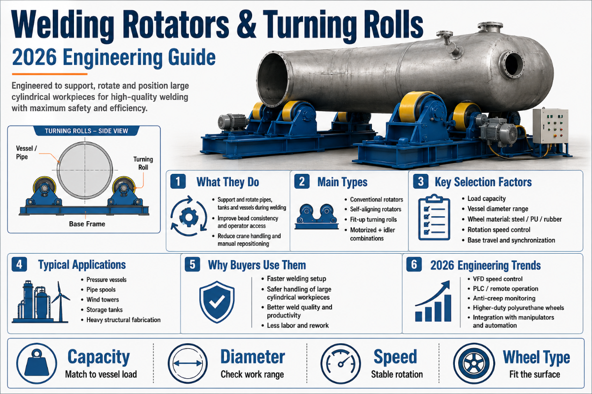
How Welding Rotators & Turning Rolls Work: A Fabrication Engineer’s Guide
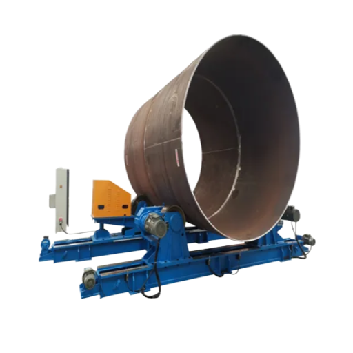
Welding rotators & turning rolls are powered roller beds that spin a cylindrical workpiece — a pipe, tank, boiler, or pressure-vessel shell — at a controlled surface speed so the welder and the arc can stay in one place while the seam comes to them. One set of drive rollers turns the job by friction; idler rollers carry the rest of the weight and keep it tracking straight. That single idea — move the part, not the operator — is why welding rotators and turning rolls sit at the heart of almost every heavy cylindrical fabrication line, from 1-tonne pipe spools to 1,000-tonne wind-tower cans.
This guide is the engineering companion to a buying decision, not a catalogue. If you already know what you need and want models and tonnage tiers, see Aubrik’s welding rotators and turning rolls range. If you want to understand how the machine actually does its job — the rotation-speed math, the wheel engineering, the physics of drift, the setup that decides whether a vessel runs true, and the standards that govern weld quality — read on.
Quick Specs: Welding Rotators & Turning Rolls
| Load capacity (per set) | 1–1,000 t standard; custom builds to ~2,000 t |
| Workpiece diameter | 200–6,000 mm |
| Rotation speed | 0.5–15 rpm, VFD stepless (large work runs well below 1 rpm) |
| Drive wheels | Polyurethane ~70–85A or steel |
| Common types | Conventional, self-aligning, anti-drift, fit-up |
| Typical work | Pressure vessels, storage tanks, pipelines, wind-tower sections, boilers |
What Welding Rotators & Turning Rolls Actually Do
What turning rolls do is deceptively simple: hold a round part on two parallel rollers and rotate it smoothly so a circumferential (C-) seam passes under a fixed welding head. Because the part turns instead of the welder walking around it, the arc sees a constant travel speed, heat input stays even, and the operator never has to reposition mid-pass. That yields a more uniform weld with fewer stop/start defects, and a large cut in manual handling.
Motorized turning rolls that rotate cylindrical workpieces at a controlled rotation speed cut worker fatigue and raise productivity at every pipe welding station, because one operator can run a long seam that once needed a crane and a crew. On a manual setup, craning a heavy vessel a quarter-turn between passes can eat 30–40% of arc-on time and tire a two- or three-person crew within a shift; on powered rolls the same job runs as one continuous pass.
At minimum, a setup is four things: a drive roller (a motor-driven wheel that spins the workpiece), one or more idler rollers (free-spinning wheels that support and balance the load), a geared motor with speed control, and a frame. “Welding rotator” and “turning rolls” describe the same family of machine — the terms are used interchangeably across regions, with “turning rolls” or “tank turning rolls” more common in heavy tank and vessel shops.
Across a fabrication shop the same roller bed shows up under several names — welding turning rolls, tank turning rolls, a pipe roller set, or simply a roller stand — but the job is constant: rotation of cylindrical workpieces so a seam can be welded in the flat position. Typical work runs from small-diameter workpieces and short pipe spools up to pressure vessels, storage tanks, heat exchangers, boiler drums, and the wind-tower cans and offshore monopiles that anchor a turbine to the seabed.
What is the difference between a welding rotator and turning rolls?
There is no functional difference — they are two names for the roller-bed machine that rotates a cylinder for welding. A welding positioner is a different machine: it clamps a part to a tilting faceplate and rotates it on one or two axes, which suits brackets, flanges, and short assemblies. Turning rolls suit long, heavy cylinders that you can’t — or shouldn’t — cantilever off a faceplate. For a structured walk-through of that choice, Aubrik publishes a rotator-versus-positioner selector.
Inside the Machine: Drive Train, Rollers & Controls
Everything a welding rotator does well comes down to one mechanism: friction drive. Torque is transmitted only where the drive wheel touches the workpiece, so the contact patch — its area, the wheel material, and the angle between the two rollers — sets how much weight you can turn — the loading capacity — before the wheel slips and the surface speed wobbles. Understand the contact patch and you understand most of the machine.
| Component | Function | Symptom if wrong |
|---|---|---|
| Drive roller + geared motor | Spins the workpiece by friction | Slip → uneven travel speed, ragged weld |
| Idler roller | Supports and balances the load | Sag, end-lift, or wandering axis |
| VFD / speed controller | Sets and holds rotation speed | Wrong surface speed → burn-through or cold lap |
| Wheel-spacing adjustment | Matches the contact angle to diameter | Too-wide spacing → low torque, slip |
Wheel spacing matters more than buyers expect. Move the two rollers apart and the workpiece sinks lower between them, increasing the wrap angle but reducing the vertical force component that generates traction; move them too close and a large vessel becomes unstable. Leadscrew- or bolt-hole-adjustable beds let you tune that balance for each diameter. Because that drive roller is a powered, rotating contact, its guarding sits under machine rules such as OSHA 29 CFR 1910.212.
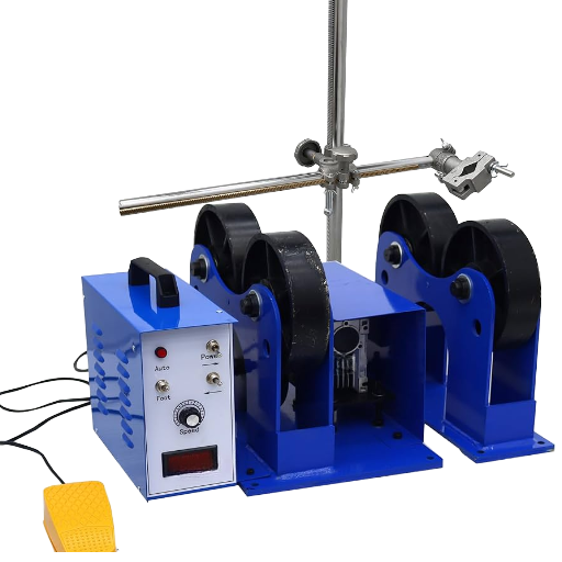
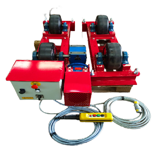
A powered drive turns the job, but the operator sets the pace. Most welding rotators and turning rolls give you speed-adjustable controls — a variable speed VFD dial on the panel, plus pendant or foot pedal options so the welder can fine-tune rotation without leaving the arc. Good controls turn torque into precise rotation and a stable rotation speed under load; cheap open-loop boxes are where stable rotation quietly slips away.
The Surface-Speed Law: Matching Rotation Speed to Your Weld
Welding cares about the surface speed at the weld — the travel speed of the arc along the seam — not the rpm of the rollers. Those two are linked by one relationship, which we will call the Surface-Speed Law:
v = π × D × N → N = v ÷ (π × D)
v = weld travel speed · D = workpiece diameter · N = rotation speed (rev/min)
v = weld travel speed · D = workpiece diameter · N = rotation speed (rev/min)
Its consequence is the part most people get wrong: rotation speed is inversely proportional to diameter. Double the diameter and you halve the rpm for the same weld speed. And for big work the numbers are tiny. Work the two examples:
- 📐6″ (152 mm) pipe, MIG at 5 in/min: N = 5 ÷ (π × 6) = 5 ÷ 18.85 = 0.27 rev/min.
- 📐48″ (1,219 mm) vessel, submerged arc at 24 in/min: N = 24 ÷ (π × 48) = 24 ÷ 150.8 = 0.16 rev/min.
Those are fractions of one rpm — which is exactly why a converted lathe makes a poor turning roll: a lathe’s slowest spindle speed is typically 50–100 rpm, hundreds of times faster than a vessel weld needs. Purpose-built welding rotators reach these low speeds through deep gear reduction plus a VFD.
| Workpiece OD | Process / travel speed | Rotation N = v ÷ (πD) |
|---|---|---|
| 6″ (152 mm) | MIG · 5 in/min | 0.27 rpm |
| 24″ (610 mm) | SAW · 20 in/min | 0.27 rpm |
| 48″ (1,219 mm) | SAW · 24 in/min | 0.16 rpm |
| 120″ (3,048 mm) wind-tower can | SAW · 30 in/min | 0.08 rpm |
📐 Engineering Note
An AC drive loses 2–5% of its rpm under load (motor slip), so the speed you dial in unloaded isn’t the speed you weld at. Set the target ~10% high, then verify the actual surface speed with the real workpiece on the rolls before the production pass. For carbon-steel MIG, weld travel is usually 4–8 in/min; a TIG root on stainless may drop to ~2 in/min; submerged arc runs much faster. Match N to the process you are actually running.
How do you calculate the rotation speed for a welding rotator?
Take your weld travel speed and divide it by the workpiece circumference: N = v ÷ (π × D). Use one consistent length unit. A 600 mm pipe welded at 300 mm/min needs N = 300 ÷ (π × 600) = 0.16 rev/min. Then add ~10% for motor slip and confirm with the loaded part. If you would rather not run the arithmetic for every job, the welding rotator capacity-match calculator pairs diameter and weight with a suitable roller set.
Polyurethane vs Steel Wheels: The 70–85A Durometer Band
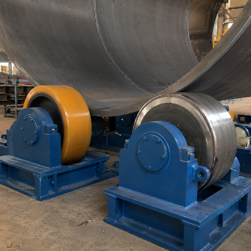
Drive-wheel material is the quietest decision on the spec sheet and one of the most consequential. Most industrial welding-rotator drive wheels use polyurethane in a hardness band of roughly 70–85A on the Shore scale — what we call the 70–85A Durometer Band. It is soft enough to grip and absorb shock, firm enough to carry load without crushing, and it doesn’t mar the workpiece the way steel can.
One honest caveat that wheel marketing tends to skip: durometer is only a hardness measurement. Per the ISO/ASTM hardness-test framework (ASTM D2240), there is no simple relationship between a durometer reading and load capacity or wear life. The 70–85A figure tells you the wheel feels right for traction; it doesn’t guarantee tonnage or service life, which depend on the polyurethane formulation, the wheel geometry, and the contact area. Treat the window as a starting point, then size on rated load, not hardness.
✔ Polyurethane (70–85A)
- High grip, non-marking on finished surfaces
- Roughly 3× the wear life of rubber
- Damps vibration → steadier surface speed
- Compliant contact patch spreads load
⚠ Steel
- Best at extreme tonnage and near-arc heat
- Tolerates spatter and scale that degrade urethane
- Can dent, mar, or score the workpiece
- Lower grip → more prone to slip; transmits shock
In practice, polyurethane for the great majority of pressure-vessel and pipe work; steel where tonnage is very high, where the wheel sits close to a hot weld zone, or where abrasive scale would chew up urethane in months.
Conventional, Self-Aligning, Anti-Drift & Fit-Up: How Each Geometry Solves a Different Problem
These four common roller geometries are not a good/better/best ladder — each one answers a specific constraint. Pick by the problem you actually have.
9 Rotator Types at a Glance
| Type | Drive / mechanism | Capacity class | Best-fit work |
|---|---|---|---|
| Conventional | Manually set wheel spacing | Light–heavy | Stable diameters; cost-sensitive |
| Self-aligning | Floating brackets find the diameter | Light–heavy | Mixed diameters; out-of-round shells |
| Anti-drift | Canted idler axes resist axial walk | Medium–heavy | Long, precision C-seams |
| Fit-up rotator | Screw/hydraulic shell alignment | Medium–heavy | Joining shell sections end-to-end |
| Pipe rotator | Narrow-spaced rolls | Light–medium | Long pipe spools |
| Elevating / growing-line | Height-adjustable frame | Heavy | Tank-building courses |
| Heavy-duty (steel wheel) | Steel rollers | Very heavy (>100 t) | Extreme tonnage; near-arc heat |
| Bogie / trolley | Multi-wheel self-aligning trolley | Very heavy | Very long, heavy vessels |
| Blasting & painting | Sealed-bearing rolls | Light–medium | Surface-prep rotation |
| Light / benchtop | Small polyurethane rolls | Light (<1 t) | Small pipe and tube |
A self-aligning welding rotator earns its keep when diameters change often: the wheel brackets pivot so the rollers find the workpiece automatically, regardless of ovality, which removes most of the manual re-spacing time. This principle is old and well documented — US patent US 4,407,621 (Self-adjusting turning roll assembly) describes a floating bracket that accommodates workpiece diameter without manual setting. A fit-up rotator, by contrast, is about geometry control before the weld — nudging two shell sections concentric so the root gap is even all the way round.
For short-run or one-off jobs, a lightweight, portable turning-roll set — bought, rented, or leased — is often more cost-effective than committing to a special-purpose heavy line you will only use a few times a year.
Why Workpieces Drift — and the Drift Triangle Behind It
“Walking” or axial drift — the vessel creeping toward one end of the bed as it turns — is the classic turning-roll headache, and on a long pressure-vessel shell it can quietly ruin an otherwise clean C-seam. It is rarely one cause. Think of it as the Drift Triangle — three forces that combine, each nudging the workpiece off its intended track:
The Drift Triangle
- Shell-shape imperfection. Out-of-round or barrelled shells present a changing radius to the rollers. The anti-drift patent literature names this as the primary driver of drift.
- Drive/idler misalignment. Rollers not truly parallel, or at unequal height, steer the part sideways — even a small height difference makes a vessel walk.
- Unbalanced job mass. Off-centre weight (nozzles, internals, fixtures) loads one roller more than another and biases the track.
The cost of ignoring it is real. Even a few millimetres of walk per revolution drags the arc off the joint, and recovering a wandered C-seam can mean grinding out and re-welding a metre of pressure-vessel seam — hours of rework on a single shell, plus the schedule hit on a code job that has to pass radiography.
Anti-drift turning rolls counter this with geometry, not brute force. As described in US patent US 8,342,493 (Anti-drift turning roll system), idler rollers are journalled on axles set slightly obliquely to the workpiece axis; that small cant introduces an axial force component pushing the part back against the drift. More recent work — for example Korean filing KR 2023-0106190 (2023) — automates the correction from a drift sensor, nudging the cant in real time. For long pipe runs that drift badly, a dedicated pipe rotator with anti-drift idlers is usually the right tool; these anti-drift systems fix the geometry instead of fighting it.
“Axial movement during C-seam welding is introduced mainly by imperfections in the cylindrical shape of the workpiece; the correction is to orient the idler axes obliquely so they generate an opposing axial force component.”
— US Patent 8,342,493 B2, Anti-drift turning roll system
Setup & Alignment: The 70% Setup-Error Principle
Here is the honest version that vendor pages rarely tell you: most turning-roll trouble is self-inflicted. Maintenance and field teams commonly report that on the order of 70% of turning-roll problems trace to setup rather than equipment failure — a field observation, not a laboratory statistic, but one that matches what most shops see. Call it the 70% Setup-Error Principle: before you suspect the machine, check the setup.
- ✔Level and parallel. Check both rollers with a straight edge and level; non-parallel or uneven-height rolls steer the part sideways.
- ✔Support at 30–40% from each end. Placing the rolls roughly a third in from each end keeps the middle from sagging and the ends from lifting.
- ✔Verify electrical phase. Reversed phase spins the rolls backward on start — a five-second check that prevents a scary first motion.
- ✔Tune wheel spacing to the diameter. Set spacing for stability and adequate traction torque, not just to fit the part on.
⚠️ Safety: powered rolls have nip points
That gap where a turning wheel meets the workpiece is an in-running nip point. US machine-guarding rules — OSHA 29 CFR 1910.212 — require guarding of rotating parts and nip points. Keep hands, sleeves, and slings clear of the roller line, and brief operators on it before the first rotation; operator safety here is a procedure, not a guard alone.
One counter-intuitive corollary: buying more capacity does not fix drift or slip. A 20–30% load margin over the actual job weight (fixtures included) is sound practice, but past that, oversizing only adds capital cost and floor space. Drift and slip are geometry and setup problems — you solve them with alignment, wheel choice, and anti-drift idlers, not with a bigger tonnage number.
Weld Quality & the Standards That Govern It
One buyer question deserves an honest answer: is there a certification a welding rotator must hold? No — there is no single “welding rotator” product certification, and we will not claim otherwise. That machine carries CE marking for its own electrical and mechanical safety, but weld quality is governed by the welding-quality framework around it, in which the rotator is an enabler of consistent travel speed.
| Standard | What it governs |
|---|---|
| ISO 3834-2:2021 | Full quality requirements for fusion welding (Part 2) |
| ASME BPVC Section IX | Welding procedure and welder qualification |
| AWS D1.1:2025 | Structural welding code for steel |
| ISO 17662:2025 | Calibration / verification / validation of welding equipment |
Newest of these, ISO 17662:2025, is the one most relevant to rotators: it covers verification and validation of equipment used to control welding process variables. Any rotator whose surface speed you can document and reproduce is exactly the kind of equipment that framework expects — which is why instrumented speed control is becoming a quality requirement, not a luxury. The pain it prevents is expensive: one failed radiograph on a code seam can force a cut-out, reweld, and re-inspection — days of schedule gone on a single pressure-vessel job, and the kind of non-conformance an ISO 3834 audit will flag.
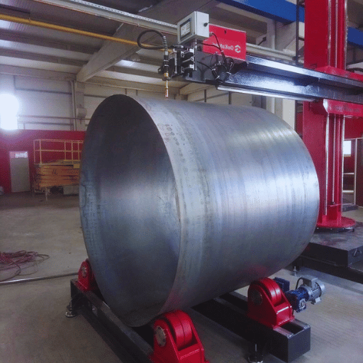
Integrating Turning Rolls Into a Welding Cell
In a real shop the rolls rarely work alone. Most heavy-fabrication cells pair turning rolls with a column-and-boom manipulator carrying a submerged-arc head: the rolls turn the can at the calculated rpm while the boom holds the wire and flux stationary over the seam. Synchronising the roll surface speed to the SAW deposition rate is the whole game — get it right and a long C-seam lays down in one continuous, even pass — the kind of repeatable result the ISO 3834 quality framework expects from a welding cell.
Inside that cell the rolls are designed to hold the seam on a constant centerline, so the arc lays one continuous weld bead pass after pass; on clad work the same steadiness lets a head run a continuous overlay around the bore. This is where automation pays off — a synchronized roll-and-boom workflow raises weld consistency, cuts changeover downtime, and makes heavy cylindrical vessels far more cost-effective to manufacture than hand-walking the weld. On a busy heavy-fabrication cell, lost changeover time can swallow close to a fifth of the working day; synchronizing the rolls to the boom is how a shop claws that hour back, shift after shift.
Aubrik builds welding rotators as part of complete lines — wind-tower production lines and H-beam welding lines among them — rather than as stand-alone units, so roller sets are specified around the manipulator, seam tracker, and flux recovery they will run with. For very long vessels, multiple roller sets share the load along the length, each carrying its 30–40% support zone, so a 12-metre wind-tower can rotates as one rigid body under the arc instead of sagging between two supports.
Maintenance, Troubleshooting & What’s Changing in 2026
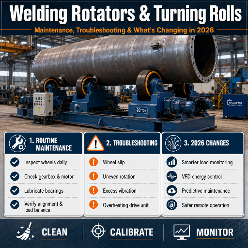
| Symptom | Likely cause | First fix |
|---|---|---|
| Workpiece slips, speed varies | Wheel wear or spacing too wide | Re-tension spacing; replace flat-spotted wheels |
| Part walks toward one end | Roll height/parallelism or mass imbalance | Re-level; engage anti-drift idlers |
| Surface speed wanders at low rpm | Open-loop drive, motor slip | Add encoder feedback; verify under load |
| Noise / vibration in drive | Gearbox or bearing wear | Inspect gear oil; replace bearings |
Clearest direction of travel for 2026 is the move from open-loop AC drives to closed-loop encoder or servo speed control. Its driver isn’t fashion: consistent surface speed has become a documented weld-quality input under frameworks like ISO 17662:2025 and in-process monitoring regimes, so a rotator that merely “turns at about the right speed” won’t satisfy a traceable quality system. For buyers chasing that traceability, the practical action is concrete: specify encoder feedback on the rotation axis, not just a VFD, on any cell that will be audited against ISO 3834. (The wider welding-positioning market — on the order of a few billion dollars and growing at mid-single-digit rates — is useful background context, but the buying decision is driven by that quality-traceability requirement, not the headline market number.)
Frequently Asked Questions
What is the difference between turning rolls and a welding positioner?
View Answer
Turning rolls support a cylinder horizontally on two rollers and spin it about its own axis, which suits long, heavy pipes and vessels. A positioner clamps a part to a tilting faceplate and rotates it on one or two axes, which suits brackets, flanges, and shorter assemblies. Long cylinders go on rolls; awkward shapes that need tilting go on a positioner.
What surface speed should I use for welding on rotators?
View Answer
Set the surface speed to your process travel speed, then convert to rpm with N = v ÷ (π × D). Carbon-steel MIG typically runs 4–8 in/min; a TIG root on stainless may be ~2 in/min; submerged arc runs faster. Because rpm falls as diameter grows, large vessels turn at well under 1 rpm. Add about 10% for motor slip and confirm on the loaded part.
Are polyurethane or steel wheels better for welding rotator drive rolls?
View Answer
Polyurethane around 70–85A is the default for drive wheels: it grips well, absorbs shock, does not mar a finished surface, and outlasts rubber by roughly three times. Choose steel only where tonnage is very high, where a wheel sits close to a hot weld zone, or where abrasive scale would quickly chew through urethane. And remember durometer is a hardness figure, not a load rating.
How much load-capacity safety margin should I add?
View Answer
Size for 20–30% above the actual job weight, including fixtures and internals. That margin absorbs weighing inaccuracy and the occasional heavier job. Going much higher mainly adds capital cost and floor space without solving drift or slip, which are setup and geometry problems rather than capacity ones.
Why do pipes walk sideways on turning rolls?
View Answer
Axial drift comes from the Drift Triangle: out-of-round shell geometry (the primary cause in the patent literature), non-parallel or unequal-height rollers, and off-centre job mass. Re-level the rolls and, for stubborn cases, use anti-drift idlers whose canted axes generate an axial force back against the walk.
Do welding rotators need a specific certification standard?
View Answer
There is no single welding-rotator product certification. The machine itself carries CE marking for safety, while weld quality is governed by the surrounding framework — ISO 3834 for quality requirements, ASME BPVC Section IX for procedure and welder qualification, AWS D1.1 for structural steel, and ISO 17662:2025 for validating the equipment that controls welding variables.
Any rotator with documented, reproducible speed control supports those systems; it doesn’t replace them. In practice, ask the supplier for the machine’s CE declaration of conformity, and confirm your own welding procedures are qualified to ASME Section IX or your governing code — the rotator’s role is to make that qualified procedure repeatable, pass after pass.
Where This Guide Comes From
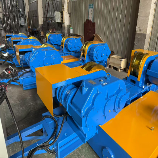
Aubrik (formerly Wuxi ABK Machinery) has built welding and cutting equipment since 1999, producing around 1,000 sets of welding equipment a year for wind-tower, pressure-vessel, and pipeline fabricators across more than 40 countries. The rotation-speed worked examples, the Drift Triangle, and the setup checklist here reflect how turning rolls behave inside the welding lines we engineer and certify to ISO 9001 and CE. Reviewed by the Aubrik (Wuxi ABK Machinery) technical team.
References & Sources
- US 8,342,493 B2 — Anti-drift turning roll system — USPTO
- US 4,407,621 — Self-adjusting turning roll assembly — USPTO
- KR 2023-0106190 A — Anti-drift turning roller for heavy-duty workpieces (2023) — KIPO
- 29 CFR 1910.212 — General requirements for all machines — OSHA
- ISO 3834-2:2021 — Quality requirements for fusion welding — ISO
- ISO 17662:2025 — Calibration, verification and validation of welding equipment — ISO
- ASME BPVC Section IX — Welding, Brazing & Fusing Qualifications — ASME
- AWS D1.1/D1.1M:2025 — Structural Welding Code, Steel — AWS