Get in Touch with Aubrik Company

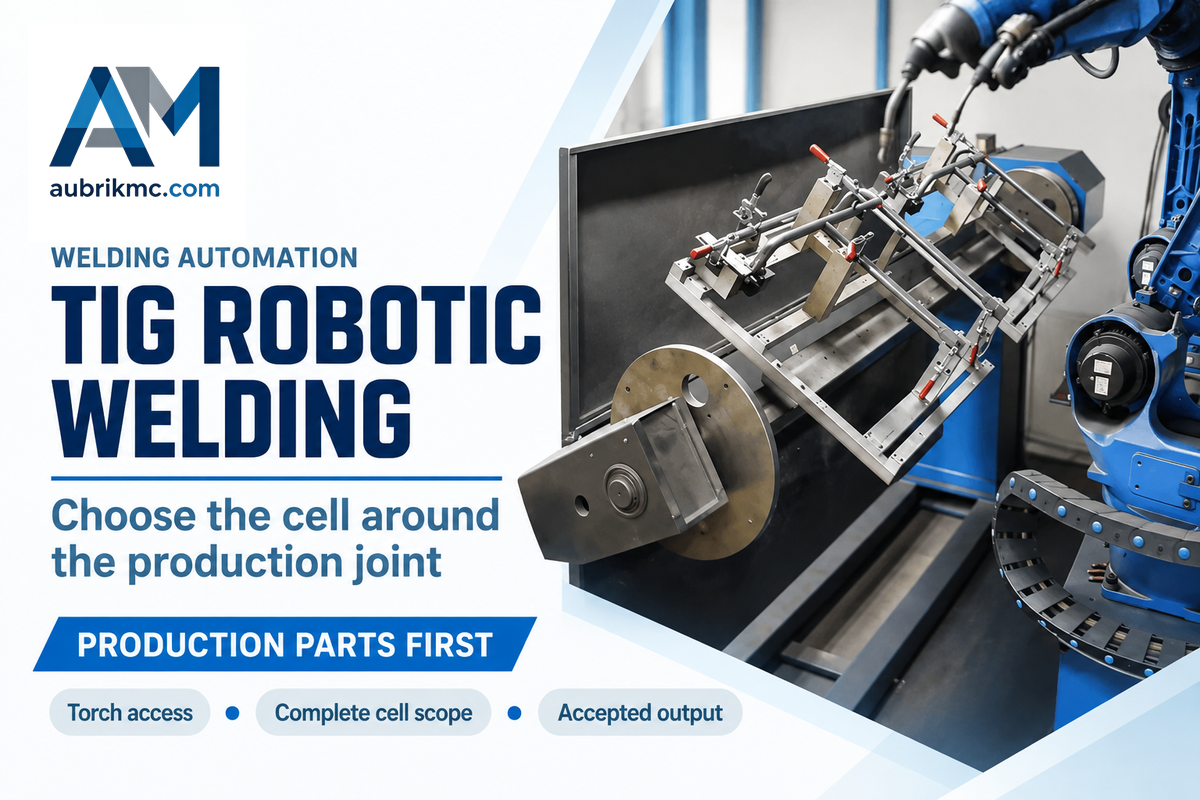
TIG robotic welding uses programmed motion to guide a gas tungsten arc welding torch, with filler added separately when required. Start with the production joint: repeatable fit-up, torch access and a reason to choose TIG. Think about whole part time and accepted output before choosing the arm or pricing the cell.
A robot can repeat its path while the weld pool moves differently. In stainless steel experiments, differences in sulfur content shifted the fusion zone toward the lower sulfur plate. Therefore, consistency of the plate and repeatability of the fixture, as well as the welding parameters, should be considered when making the automation decision.
TIG robotic welding suits recurring, accessible joints that need controlled heat and weld finish; the buying decision depends on fit-up, complete cell scope and cost per accepted part.
Process at a glance
- Electrode: nonconsumable tungsten; filler is separate or omitted.
- Shielding: inert gas, commonly argon or helium.
- Motion choices: robot arm, coordinated positioner or an orbital head for suitable circular joints.
- Purchase basis: a demonstrated production joint and a defined installed scope.
Key takeaways
- Choose TIG for the joint requirement, then choose the motion platform.
- Match the torch and wire envelope to the actual fixture.
- Count loading, cleaning and inspection in the cycle.
- Keep robot positioning accuracy separate from joint-gap tolerance.
How TIG robotic welding works
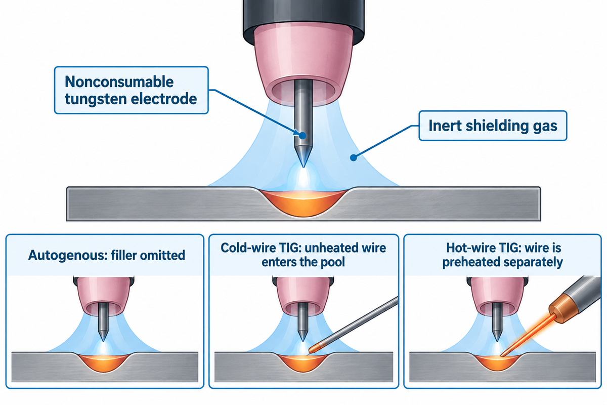
A robotic TIG system separates movement, heat and filler control. Think of the robot as a steady hand carrying the torch: the power source creates the arc, shielding gas protects the pool, and a feeder supplies wire when the joint needs it. The coordination of the system is the key integration challenge.
The American Welding Society’s GTAW explanation identifies a non-consumable tungsten electrode. Unlike MIG welding, the electrode does not continuously feed into the weld.
| TIG architecture | Filler arrangement | Selection consequence |
|---|---|---|
| Autogenous | No added filler | Close-fitting joints must supply the required weld volume. |
| Cold-wire TIG | Unheated wire enters the pool | Wire aim, start timing and clearance enter the process specification. |
| Hot-wire TIG | Wire is preheated separately | Additional equipment and control interfaces enter the cell scope. |
Can robots TIG weld?
A robot can carry a TIG torch and coordinate the welding process with a compatible power source, gas controls and optional wire feeding. The system needs process specific interfaces and a qualified setup. A robot already used for MIG requires the appropriate TIG equipment and integration to perform TIG.
The core tasks of the TIG weld process that still apply when TIG welding with a robot are preparing the joint, maintaining the electrode, and controlling arc length. AWS notes that filler metal can be added as a separate rod and that close-fitting joints can be welded without filler. A complete automated TIG system sequences ignition, current changes, filler starts when needed and crater filling. When reusing an existing arm, specify in the purchase order the control interface for each of these functions.
Which parts are suitable for automated TIG welding?
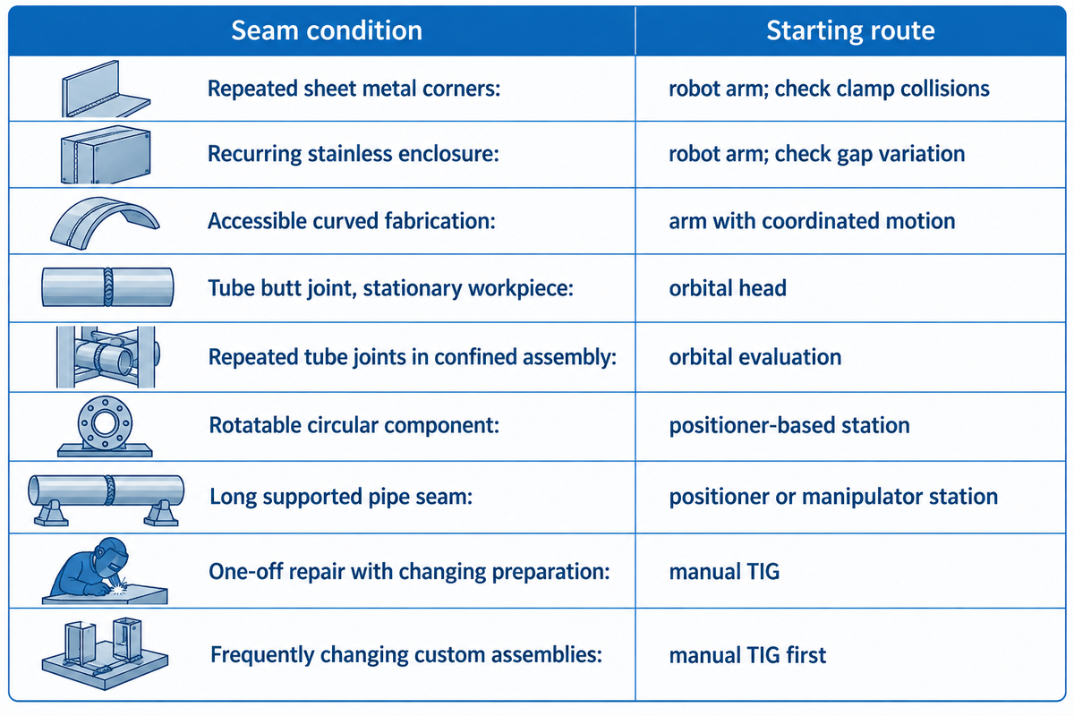
Recurring parts with stable joints and clear torch access are the strongest candidates for automated TIG. Thin stainless steel fabrications and assemblies with demanding finish requirements deserve evaluation, but material alone does not decide suitability. Joint geometry, incoming variation and the ability to present the seam consistently determine the practical route.
The 4-Route Seam-to-Cell Fit Matrix below routes a part toward an arm, orbital head, positioner or manipulator station, or manual TIG.
| Part or seam condition | Starting route | Reason | Rejection condition |
|---|---|---|---|
| Repeated sheet metal corners | Robot arm | Programmed access to several seam directions | Torch or feeder collides with clamps |
| Recurring stainless enclosure | Robot arm | Repeatable sequence around an assembly | Variable gaps exceed the developed process window |
| Accessible curved fabrication | Robot arm with coordinated motion | Controls torch approach through the seam | Position changes cannot preserve access |
| Tube butt joint with a stationary workpiece | Orbital head | Electrode travels around the circular joint | Head cannot fit around the tube |
| Repeated tube joints in a confined assembly | Orbital head evaluation | Compact joint-specific motion | Clearance or joint form is incompatible |
| Rotatable circular component | Positioner-based station | Part rotation can simplify torch movement | Clamping distorts the joint |
| Long pipe seam with controlled support | Positioner or manipulator station | Supports workpiece presentation | Support deflection changes the seam position |
| One-off repair with changing preparation | Manual TIG | Skilled adaptation between irregular joints | Recurring demand later justifies dedicated tooling |
| Frequently changing custom metal assemblies | Manual TIG first | Avoids programming and fixture work for every variation | A stable part family emerges |
Consider an enclosure that repeats every shift, but a flange is blocking the filler nozzle. Adjusting robot reach won’t provide the required clearance. A revised assembly sequence or fixtures may enable the part to be processed. Buying a larger arm first may still leave the joint obstructed. Such TIG welding applications require access reviews at the joint level before the equipment layout is finalized.
Fixture Guidance presents Melton Machine’s recommendations to locate before clamping and to test clamp force on actual thin sections. For pipe fabrication, pipe welding manipulators provide another equipment route when the workpiece presentation favors a supported torch station.
Robotic TIG vs MIG, orbital welding and manual TIG
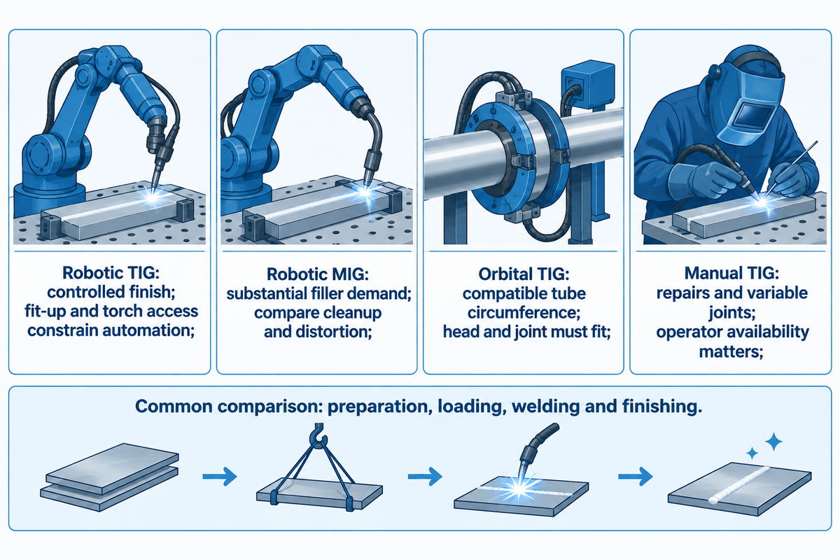
Choose robotic TIG when controlled filler and heat input serve the product requirement; compare MIG when deposition is the main constraint. TIG welding retains its place for different work requirements and fits better in this case. The fair comparison includes preparation, loading and finishing for the same accepted part.
| Method | Useful starting application | Production tradeoff |
|---|---|---|
| Robotic TIG | Recurring joints needing controlled finish | Fit-up and torch/wire access constrain automation. |
| Robotic MIG | Fabrications with substantial filler demand | Compare spatter, cleanup and distortion against the drawing. |
| Orbital TIG | Compatible tube or pipe circumference | The head and joint preparation must fit the assembly. |
| Manual TIG | Repairs, prototypes and variable joints | Output depends on operator availability and sustained technique. |
Swagelok Edmonton states orbital welding is electrode travel around a stationary workpiece. A rotary welding positioner instead rotates the workpiece. These choices for motion address different access constraints.
A 2020 study by Mitru and colleagues examined an eight-axis GTAW system on 3.2 mm 304L test pieces with 1.2 mm ER308L filler. Welding time fell 50%, total parts execution time fell 25%, and argon consumption fell 44% in that comparison.
For a bracket with a large groove, speed and deposition may favor robotic MIG welding. For an enclosure whose appearance drives downstream polishing, TIG and MIG welding deserve a whole-part comparison. Record the time required to achieve the specified finish rather than assuming that a cleaner-looking bead eliminates finishing. Welding speed, alone, leaves metal fabrication operations out of the productivity comparison.
The Fabricator’s process comparison also emphasizes upstream repeatability. Where tack preparation dominates the shift, a faster arc can leave the factory’s actual constraint unchanged. Compare welding technologies for your metal products using the time spent preparing, loading, welding and finishing the same accepted part.
Choosing a TIG welding robot and cell
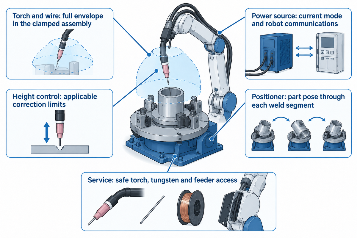
Select the welding robot around the loaded fixture and complete torch envelope. Reach, alone, misses feeder clearance, cable motion and angle required to approach the joint. The power source and current mode, as well as the control interface, then must align with the material and welding method developed for that part family.
A TIG welder connected to a robot arm requires controls for ignition, current adjustment, and fault handling throughout welding operations, as well as a start signal. Use a generic robot listing to shortlist arms, and then use process development to select the equipment and procedure for aluminum and stainless steel.
| Equipment feature | What to specify | Failure it addresses |
|---|---|---|
| Torch and wire package | Full envelope in the clamped assembly | Nozzle collision or inaccessible filler angle |
| Power source | Required current mode and robot communications | Uncontrolled starts or unavailable process settings |
| Height control | Applicable arc voltage control and correction limits | Arc-length variation along the path |
| Positioner coordination | Part pose through each weld segment | Poor access or unfavorable welding position |
| Service arrangement | Safe torch, tungsten and feeder access | Long recovery after routine maintenance |
Robot repeatability describes motion. The allowable joint gap belongs to the developed weld process. Touch sensing or seam tracking can correct certain positional deviations within set limits; it can’t supply missing metal across an uncontrolled gap. Assess precision and weld quality by checking weld positioning and joint acceptance, separately from the arm’s specified precision welding capabilities.
A cobot welder can be easier to program for certain tasks, while traditional robots may be suited to other production layouts. Compare collaborative welding systems for the entire application, including risk control. Our robotic welding machine configurations provide an equipment starting point for defining the required TIG package. Program the robot around the approved sequence after the process and tooling are established.
Robot welding cost: compare the complete TIG cell
A helpful TIG cell price covers the agreed scope of the work: welding equipment, tooling and integration, with acceptance duties defined. Arm-only prices and complete robotic welding systems have different scope boundaries. Compare matching scope first, then calculate cost per accepted part using the same demand, shift time and accounting basis.
How much is a robotic welder?
Melton Machine’s general pricing guide puts entry-level robotic welding cells at US$80,000 to US$150,000, particularly cobot configurations for simpler applications. Generally speaking, that’s a comparison to robotic-welding. Compare a TIG cell configured for your part, including the arm, torch, power supply, fixtures, controls, protective measures and any required filler equipment. Include process development and installation costs in each total, as these costs can reverse a ranking based on arm prices alone.
For integrated welding cells, procurement should compare included tooling and commissioning against the same acceptance test. Finance gets allocated operating costs; the plant manager gets the resulting output at demand. General price bands for robotic-welding mix processes and configurations, so a TIG purchase requires a part-specific installed quotation.
| Quote item | Comparison boundary | Budget owner |
|---|---|---|
| Arm and welding package | Compatible controller, torch and power source; feeder where filler is used | Engineering |
| Fixtures and part motion | Production part families and changeover tooling | Production |
| Safeguarding and extraction | Installed application and factory interfaces | Plant management |
| Commissioning and training | Programs, trials and handover responsibilities | Procurement |
| Operating costs | Labor allocation, gas, consumables, service and capital charges | Finance |
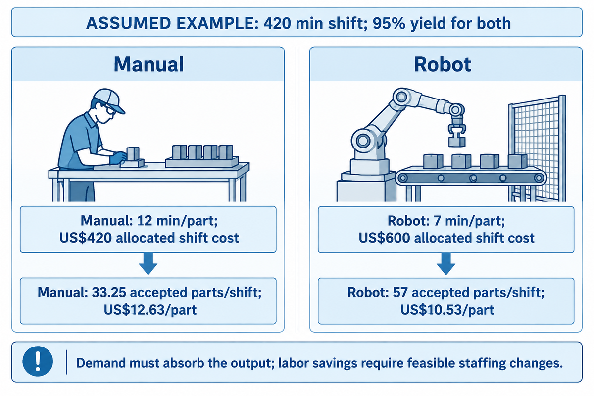
Worked example with assumed inputs: take a 420 min shift, manual cycle of 12 min/part, robot cycle of 7 min/part, and 95% yield for both. Suppose total allocated shift costs are US$420 and US$600, respectively.
Accepted output = available minutes ÷ complete-part cycle × yield. Manual output is 420 ÷ 12 × 0.95 = 33.25 accepted parts/shift ; robot output is 420 ÷ 7 × 0.95 = 57 accepted parts/shift . Cost per accepted part is therefore 420 ÷ 33.25 = US$12.63 versus 600 ÷ 57 = US$10.53 , rounded. Demand must absorb the output, and labor savings require an achievable staffing change or redeployment. Staffing changes and redeployment must yield labor cost savings.
Changes to the process also impact comparisons. A 2024 experimental study reported 2 min for robotic activated-TIG vs. 10 min for manual multipass TIG on 6.14 mm P91/304L joints. Flux and interlayer and filler arrangements also varied. The difference in time belongs to the combined process comparison, not to robot motion alone.
Where robotic TIG welding loses repeatability
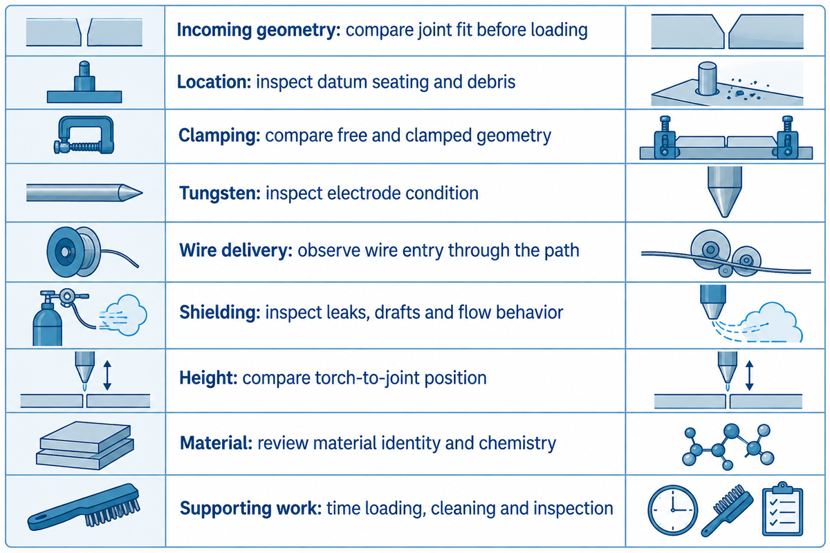
Robotic TIG loses consistency when the joint presented to the torch changes, the arc becomes unstable or filler reaches the wrong place. Diagnosis begins with the observed defect and its timing. Separate geometry, material and process causes before changing the taught path; each calls for a different corrective action.
Why is TIG robotic welding not working?
Start with the earliest repeatable change: part seating, tungsten condition, gas coverage, wire entry or arc length. A defect that follows a material batch points toward different causes from one that appears after a torch service. Save the program and compare a known setup before making several parameter changes together.
Miller’s TIG troubleshooting guidance explains that too much gas flow can create turbulence and draw in contaminants. Too much flow can also compromise the shielding gas. Shortening an excessive TIG arc can improve directional control, but welding engineers still need to relate the adjustment to the qualified procedure and joint.
| Fault group | Observed symptom | Discriminating check | Intervention |
|---|---|---|---|
| Incoming geometry | Intermittent open root | Compare joint fit before loading | Correct preparation or reject out-of-window parts |
| Location | Seam offset follows loading | Inspect datum seating and debris | Restore the locating surfaces |
| Clamping | Thin section changes shape | Compare free and clamped geometry | Revise support and clamp force |
| Tungsten | Arc changes after contact | Inspect electrode condition | Restore the specified electrode preparation |
| Wire delivery | Filler stubs outside the pool | Observe wire entry through the path | Correct nozzle position or timing |
| Shielding | Porosity or unstable arc | Inspect leaks, drafts and flow behavior | Restore the specified gas coverage |
| Height | Fusion changes along a contour | Compare torch-to-joint position | Correct path or bounded height control |
| Material | Fusion shifts across a dissimilar batch | Review material identity and chemistry | Evaluate the material/process interaction |
| Supporting work | Good welds but low shipped output | Time loading, cleaning and inspection separately | Address the actual constraint |
“A fixture cannot fix poor incoming parts.”
The results of Mishra and colleagues’ stainless-steel GTAW experiments showed the fusion zone moved toward the lower-sulfur steel. Should asymmetric fusion occur after a batch change and the position of the torch remains stable, check the difference in sulfur content before modifying the programmed torch path.
Which suppliers offer robotic TIG welding systems?
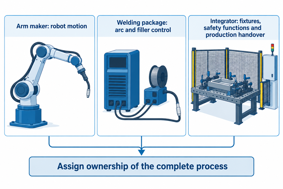
THG Automation supplies robotic TIG integration, while documented OTC and Liburdi installations show other equipment routes. An arm maker supplies motion; the welding package supplies arc and filler control; the integrator combines these with fixtures, safety functions and production handover. Assign ownership of that complete process when comparing suppliers.
A production example is Universal Robots’ Raymath case study, which details the use of THG’s cold-wire feed push/pull TIG system to manufacture stainless steel and aluminum parts. The case study provides a good example of a working TIG integration rather than inferring process capability from the robot brand.
A documented installation helps identify the distinction. Dalian University of Technology lists an OTC FD robot with a DA300P TIG source, cooling and wire feeding. Its published 10–300 A current range describes that installation. The same university also lists MIG and plasma configurations using FD series robots.
The Ma²JIC laboratory capability listing identifies a custom five-axis Liburdi TIG system for adaptive welding research. This is different from a standard production system.
At Aubrik, our welding automation equipment includes robots and cells. Bundle the TIG process and part-handling system together, so that one party owns the welding solution. Compare robotic welding solutions by this responsibility split, instead of treating every supplier of robotic systems as a complete cell integrator.
Proving weld quality on production parts
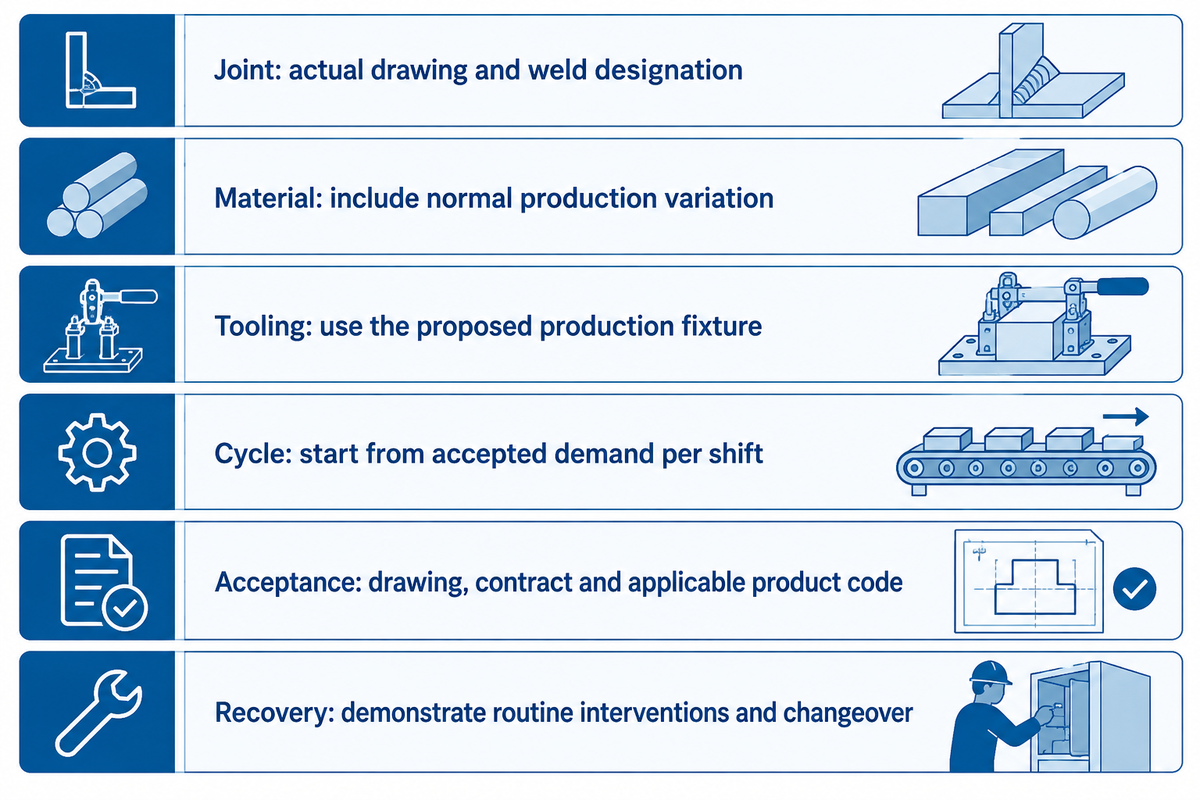
Include real preparation and handling in the trial. A visually smooth demonstration bead answers only part of the question; the handover needs acceptable welds at the promised complete-part cycle.
Identify the joint in the drawing. The fabricator will select a welding procedure for the joint that satisfies the applicable code and contract requirements. The drawing, contract specifications and product code provide the acceptance criteria for the finished weld. ISO 14732:2025 specifies qualification requirements for welding operators and weld setters engaged in mechanized and automatic welding of metallic materials. The arm’s repeatability specification describes how consistently it returns to a position. Assess the finished joint against the weld acceptance criteria.
Suppose production needs 50 accepted parts in 420 min at an assumed 95% yield. The allowable average complete-part cycle is 420 × 0.95 ÷ 50 = 7.98 min/part. That budget must accommodate the operations assigned to the cell, including the observed changeover and recovery burden.
| Parameter | Trial requirement | Why it matters | How to verify |
|---|---|---|---|
| Joint definition | Start with the actual drawing and weld designation | Defines the required weld | Mark trial joints against the drawing |
| Material and preparation | Include normal production variation | Exposes fit-up sensitivity | Compare representative prepared parts |
| Access and tooling | Use the proposed production fixture | Reveals torch and wire obstructions | Observe the complete seam path |
| Cycle requirement | Start from accepted demand per shift | Connects process time to output | Time the agreed complete-part boundary |
| Weld acceptance | Drawing, contract and applicable product-code acceptance criteria | Defines which welds pass | Record the agreed inspection results |
| Changeover and recovery | Include planned routine interventions | Exposes support needs | Demonstrate restart and part-family change |
For a rotating assembly, inspect the welds after the complete clamping and orientation sequence. Producing high-quality welds in a stationary coupon doesn’t establish quality throughout the sequence. Quality, production and maintenance should each sign off their own handover duties. Store the accepted program revision with the process settings and fixture identification so later troubleshooting starts from a known configuration.
Industry outlook: safer integration and practical utilities
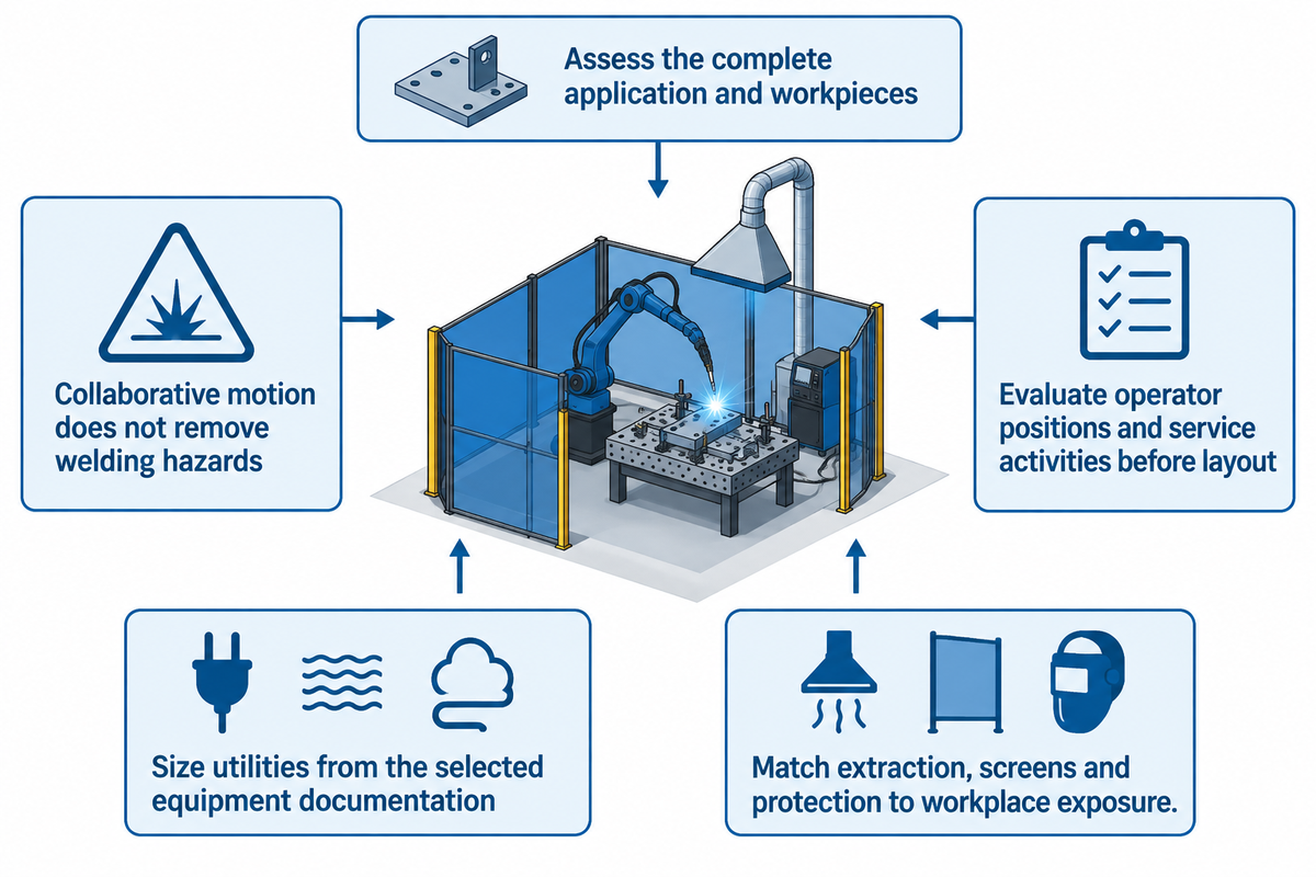
The main change for buyers is a more complete application of the robot safety process. The 2025 robot safety revisions bring the specific welding task, workpieces and supporting equipment into the integration discussion. That matters for welding because safe motion is only one consideration alongside managing the arc, hot metal and airborne contaminants.
A3’s explanation of the updated ISO 10218 standards says the 2025 editions replace the 2011 versions. This revision details the shift to the robot application and its workpieces and programmed tasks. For a buyer, this change means the protective measures have to be adjusted to the task and the equipment in the surrounding work environment.
The ISO 10218-2:2025 catalogue covers integration through operation and maintenance. Safety functions for a collaborative task may come from the collaborative robot, a protective device or a combination. People who work alongside a welding cobot still face welding hazards. The planned operator positions and service activities belong in the application assessment before the floor layout is fixed.
Integration & Utility Requirements
Size utilities from the selected equipment documentation. The robot, TIG power source and cooler may have different electrical connections and service requirements. Gas must reach the torch under operating conditions, and separate provision must be made for back-purging if the procedure calls for it. Define cable routes and grounding with the equipment supplier so routine motion does not strain the service lines.
OSHA’s welding safety resources describe hazards associated with welding and related work. Fume extraction, screens and protective equipment must match the process and exposure in the workplace. A robot system also needs a service plan for welding torches, consumables and recovery from faults.
Specify responsibility for utility connection, protective controls and commissioning before shipment. Quotes for the arm’s power connection may not include cooling or extraction, leaving an installation gap. Automated welding requires a documented, maintainable application with clear interface ownership. This is the case even for using robotic equipment for a different part family.
Frequently asked questions
What is another name for TIG welding?
Gas tungsten arc welding (GTAW) is another name for tungsten inert gas (TIG) welding. Both names describe an arc formed with a nonconsumable tungsten electrode under inert shielding gas. Adding a robot changes how the torch moves; it does not create a different basic welding process or make filler mandatory.
What gas is used for TIG welding?
AWS identifies argon and helium as the inert gases typically used to shield the molten weld pool in TIG welding. Choose the gas to suit the material and welding procedure. Set the flow according to the procedure, accounting for torch hardware, joint access and drafts that affect coverage. Millerwelds explains that excessive flow creates turbulence that can draw airborne contaminants into the shielding gas and destabilize the arc.
Are TIG robotic welding systems safe?
Yes, a TIG robotic welding system can be operated safely when protective measures for its particular task are assessed, implemented and maintained. Motion controls address only part of the exposure. Arc radiation, fumes, electrical hazards and hot parts also require attention, including during maintenance and recovery. A collaborative arm doesn’t make every welding layout suitable for people to enter during operation.
Can I teach myself to TIG weld?
Self-study can introduce TIG technique. Production work needs supervised practice and workplace training, with additional instruction for programming, process setup and safe recovery on automated equipment.
What are the benefits of robotic TIG welding?
Robotic TIG can repeat a developed torch path and coordinate heat with separate filler delivery. Recurring joints can benefit from a consistent sequence and reduced dependence on sustained hand motion. Automating the welding process retains the need for stable incoming parts and fixtures. When loading or inspection dominates the cycle, arc automation alone may deliver little additional output. Compare accepted parts over the complete shift and include the time needed to maintain the process.
Is TIG robotic welding still used?
Yes. Raymath uses a THG cold-wire push/pull TIG system for stainless steel and aluminum parts, as documented in the production case study discussed above.
How do you become a robotic welder?
Build welding-process knowledge alongside robot operation and troubleshooting skills. A skilled TIG background helps explain the pool behavior, while automation adds frame setup, path teaching, sequence control and recovery. Begin with supervised work on the actual equipment and learn the plant’s safe operating procedures. Practice checking datum frames, locating a seam and recognizing a change in arc behavior before taking responsibility for a running cell. Qualification duties depend on whether the role sets the process, adjusts parameters or only loads parts. ISO 14732 distinguishes relevant operator and setter roles; workplace training remains necessary for loading duties too.
Will you automate TIG welding? Send Aubrik the part drawing, material, joint details and accepted demand per shift. Provide the current handling sequence and finish requirement to ensure the discussion is covering the complete cell. Discuss a TIG cell for your parts using the acceptance and scope checklist above.
Related reading
- Robot configurations for a complete welding package
- Collaborative welding equipment and application choices
- Integrated cell scope and part handling
- Rotary workpiece positioning
References & Sources
- American Welding Society: What Is GTA Welding?
- Mishra et al.: Experimental and theoretical GTAW study of stainless steels
- Mitru et al.: Eight-axis adaptive robotic GTAW study
- Journal of Manufacturing and Materials Processing: Robotic A-TIG comparison
- The Fabricator: Robotic GTAW or GMAW?
- Dalian University of Technology: Welding laboratory equipment
- Ma²JIC: Laboratory capabilities
- ISO 14732:2025: Welding operator and setter qualification scope
- A3: Updated ISO 10218 FAQ
- ISO 10218-2:2025: Robot application integration
- OSHA: Welding, Cutting, and Brazing