Get in Touch with Aubrik Company

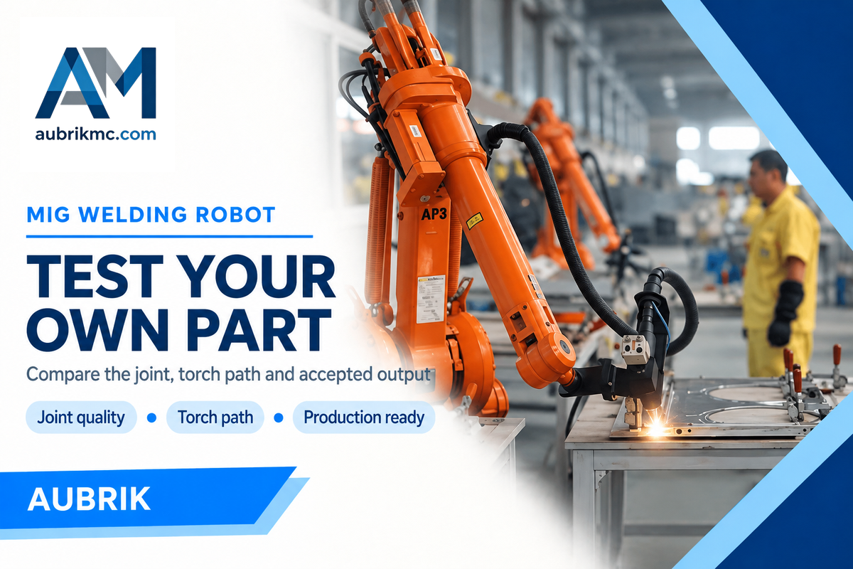
Choose a MIG welding robot by running your own part in the proposed cell. Check whether the loaded joint repeats, whether the torch can follow the entire seam, and how many pieces pass inspection in the time available. Then compare quotations for the same installed equipment and acceptance test.
Imagine a batch of bent brackets lined up next to the welding table. They have the same drawing number, but one has a flange that has sprung back a little farther after bending. A robot can repeat yesterday’s path exactly, and miss today’s joint. That bracket belongs in the supplier trial. Testing that bracket can tell you more about cell selection than the arm specification alone.
What a MIG welding robot does at the joint
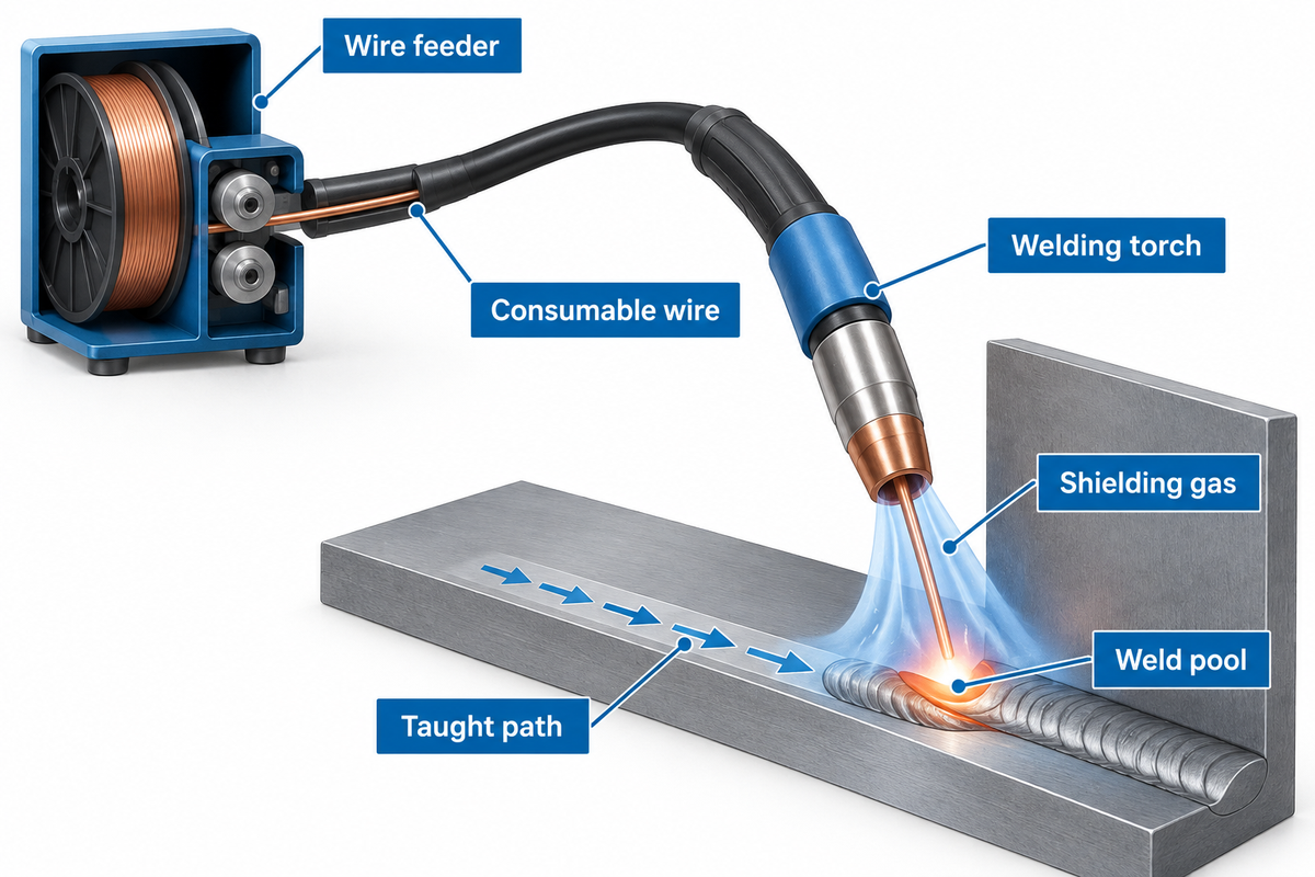
A MIG welding robot moves a welding torch along a taught joint, while a wire feeder delivers the consumable wire electrode. AWS says the wire feeds continuously through the gun. The arc between the wire and the workpiece melts the filler and base metal. Shielding gas protects the weld pool. The robot can repeat the weld across a batch of frames if the fixture holds each seam on the taught path. On a bent bracket, the flange near the locator may return to the same position while the free end shifts. When comparing cells, check whether the torch follows the actual seam at both ends of each bracket.
Can MIG welding be automated?
Yes, the robot controller calls the weld schedule and synchronizes arc start, torch travel and the crater end sequence with the power source. The welder selects the approved wire, gas, transfer mode and parameters, and the loading operator seats the designated part faces against the fixture stops. The American Welding Society describes the underlying welding process as gas metal arc welding (GMAW). Industrial catalogs often group MIG and MAG equipment together. Shielding gas determines which term is applicable.
Follow the control chain for the robotic MIG welding process demo. Which device detects a seam shifted by a tack? What stops the welding operation if the wire fails to feed? Knowing the answers tells you which issues the equipment identifies and which issues require an inspection.
A side-by-side trial on production parts is a practical test for automated welding. Compare manual MIG welding and automated MIG welding on a part your skilled welders already make. Keep the drawing revision and acceptance criteria the same. Look for differences in weld quality.
Which metals can a robotic MIG welder weld?
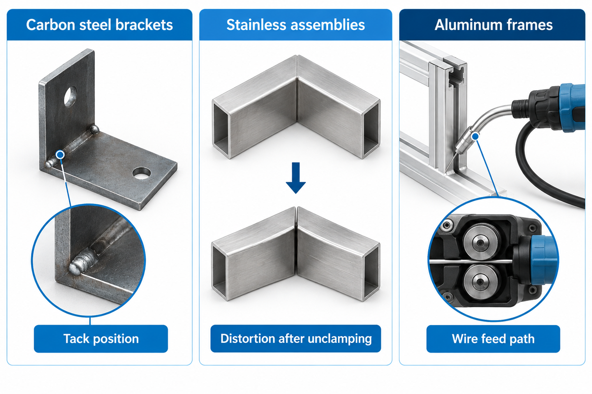
What will a MIG welder weld?
In a MIG welding system, the power source, shielding gas, filler wire and qualified procedure determine what the setup can join. A material name alone doesn’t give the supplier enough information. Send the actual alloy, thickness on either side of the joint, condition of the surface and weld symbol.
| Part family | What to ask the supplier to demonstrate | What to record |
|---|---|---|
| Carbon steel brackets | Start, tie-in and finish on a bracket prepared the same way as production stock. | Tack position, scale or coating and inspection result. |
| Stainless assemblies | Run the specified filler and gas on the joint, including any heat-sensitive corner. | Procedure, shielding arrangements and distortion after unclamping. |
| Aluminum frames | Feed the selected wire through the proposed torch at the least favorable wrist pose. | Feed path, liner, drive rolls and repeatability of starts. |
A robotic MIG welder can weld steel and aluminum, but the wire-feed setup matters when switching between the two. Lincoln Electric notes that a helically wound steel liner commonly used for steel wire can scratch soft aluminum wire and collect the shavings. In the push-pull system described by the company, an assist motor at the feeder pushes the wire while a motor in the gun pulls it. Include the time to change the torch, liner, gas and spool in the mixed-batch estimate.
Changing the metal can change the bid. A robotic MIG welding system quoted for steel may need a different liner and drive rolls for aluminum. For mixed welding applications, read the process callout on each drawing. If a drawing requests TIG welding or plasma welding, flag it for a separate process review before adding it to the sample lot.
In Sikström and Öberg’s fillet-weld experiment, researchers employed 1.2 mm copper-coated steel wire and supplied shielding gas at 20 L/min. Those values describe the test setup. Use the procedure for the actual alloy and joint on the purchase trial.
Will the joint stay under the torch?
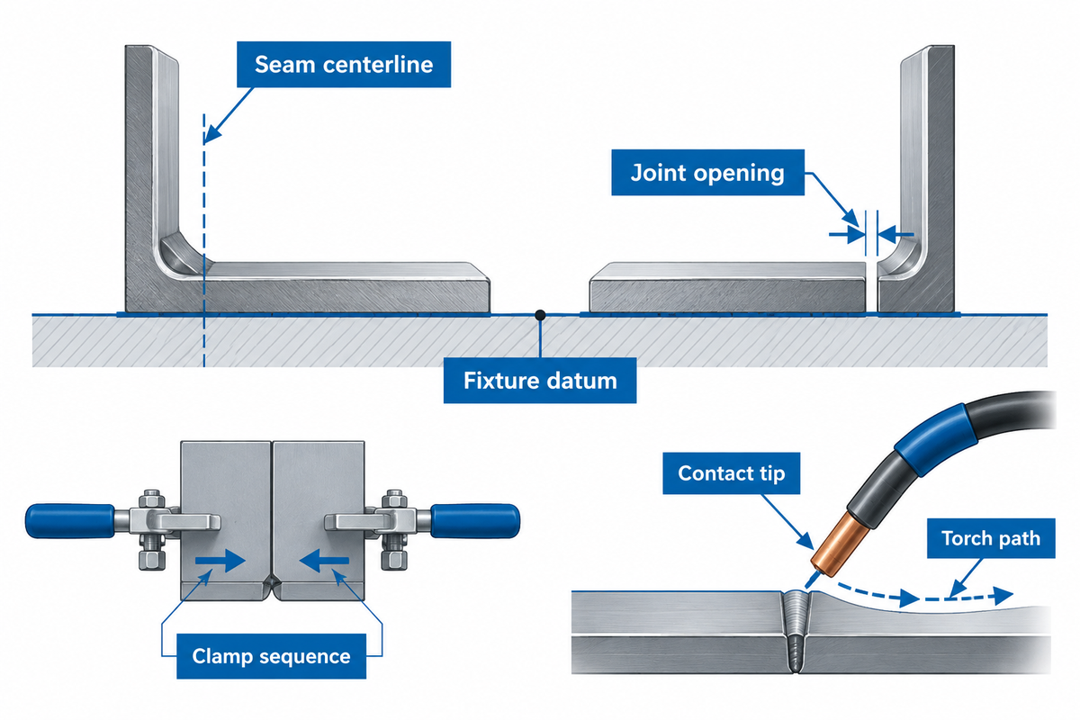
Yes, if the fixture reliably holds the joint on the torch path along the entire seam (i.e. at the starting point, center, and end marks). When assemblies are loaded from different production lots, use the standard clamping sequence to position the parts, and note the position of the seam center with respect to a fixture datum at each of the marks. In a separate column, note the opening between the mating parts. A closed clamp can hold an assembly in the right location while leaving a gap in the joint.
Miller mentions a target location for joints on simpler parts of approximately half the diameter of the wire used. The acceptance requirements applicable to your parts may be specified in the drawing or referenced in the welding procedure. Even with the wire correctly located, a changing joint opening can affect penetration. Sikström and Öberg studied how joint gap affects penetration in one-sided fillet welds and explained why an inspector generally cannot judge penetration from the finished surface.
If either of the two robotic systems misplaces a bead, check how the part seats against its locators. Don’t assume the fixture is at fault. Check the contact tip and verify the tool center point using the cell’s approved setup procedure. A worn contact tip can change where the wire emerges even if the robot repeats its programmed pose. Keep the torch-angle check on the trial sheet. Have the welding and quality leads select representative extremes and agree how the weld will be assessed.
When the clamp closes, watch the torch angle at the far end. Reducing travel speed changes heat input along the programmed path. It can’t move the programmed path onto a missing joint.
Choose a cobot or an industrial welding cell
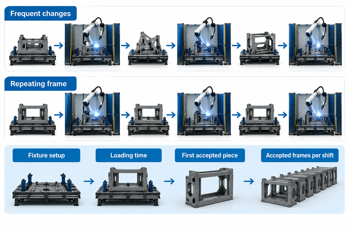
A collaborative robot set up for cobot welding can suit frequent changes between short runs when the operator can quickly teach a new seam and release the first acceptable part. A conventional welding cell is worth testing when welding the same part repeatedly takes up most of a shift. For either of these layouts, a rotary welding positioner may present another face without the need for manual refixturing. Batch size alone can’t resolve the choice.
| Shop condition | Test both proposals on | What can change the decision |
|---|---|---|
| Many revisions of a bracket | Time from the released drawing to the first accepted piece. | Fixture setup and program verification can exceed arc time. |
| A repeating frame on a production line | Accepted frames per shift, with routine loading and tip changes. | Part supply, inspection or unloading may set the pace. |
| Heavy work or a seam on the underside | Positioner load, access and an actual change of orientation. | A second setup can erase a faster welding pass. |
The US Occupational Safety and Health Administration treats the arm, end effector, controls, fixtures and safeguards as an integrated system. Even in a collaborative application, the arm carries an arc-welding torch. Assess the site risks for arc radiation, spatter, hot parts, fumes and the positioner’s motion. The 2025 US robot safety standard uses the term “collaborative application.” Have the integrator and the site’s safety lead identify who validates the installed arrangement.
Two robotic welding cells can use the same type of industrial robot and still vary in how easily the operator loads the jig. For repetitive welding on a high-volume production line, time the operator loading the heavy part as well as the arm making the weld. When comparing traditional robots and collaborative robots, who will demonstrate changeover using your clamps and lifting equipment?
For arrangements where operator, guarding and arm occupy the same floor space, see the welding cell layout guide.
Size the arm, torch and positioner around the part
Aubrik lists 1,400 mm of reach for its collaborative configuration and 1,700 mm for its standard industrial cell. The extended configuration lists 2,000 mm plus external axes. Read the comparison in the robotic welding machine configurations and request a layout that dimensions the arm and any rail separately.
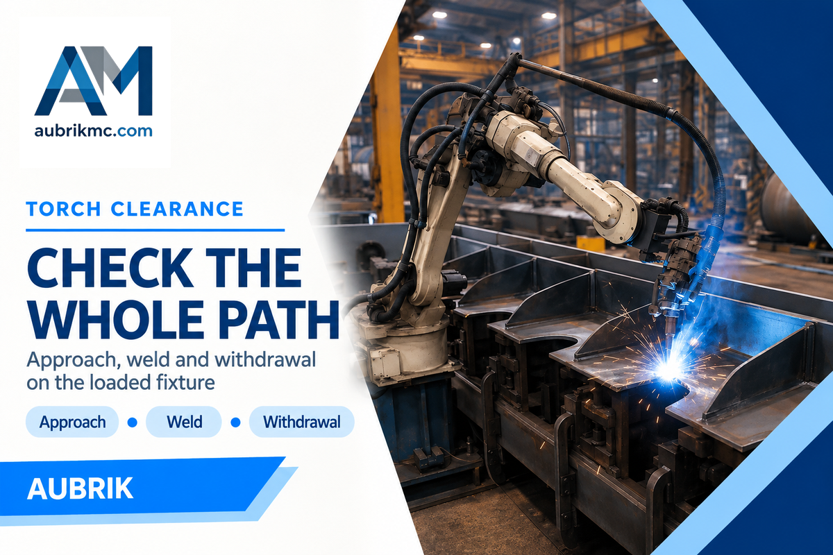
On an automotive bracket, ensure the gun clears the return flange. On long frames, the far flange may be inside the arm’s nominal reach. Check that the torch has clearance at the angle the weld requires. The torch neck still needs room to maintain its work angle, the wrist must be able to take a continuous path through the corner, and the cable needs a route past the clamps. Dry runs of approach and the entire weld and withdrawal should reveal any constraints. Isolated checks of end positions may not reveal problems that occur partway through a turn.
Size the positioner for the combined mass of the assembly and fixture, and account for the offset of their combined center of gravity from the axis of rotation. Different demands may be placed on the same rotary axis by a large, light frame and a compact, heavy casting. Provide drawings of the largest assembly and the smallest awkward one, labeling the workpiece mass and showing the fixture base and closed clamp handles. Check torch clearance for the angle the weld requires. In SwitchWeld’s example, the cobot holds the torch at 45 degrees and welds a steel part which is clamped to a table.
A robotic arm that can touch the start of a seam may run out of wrist movement before the end. With complex parts, have the bidder show approach, welding arc and exit on the fixture drawing. If the bid includes offline programming, have the bidder show how a technician corrects a mismatch at the teach pendant.
For a cylindrical assembly on rollers, the rotator sizing guide considers drive torque and roller angle. A faceplate fixture, on the other hand, requires the loaded center of gravity and its distance from the tilt axis.
How much does a robotic welder cost?
How much is a robotic welder?
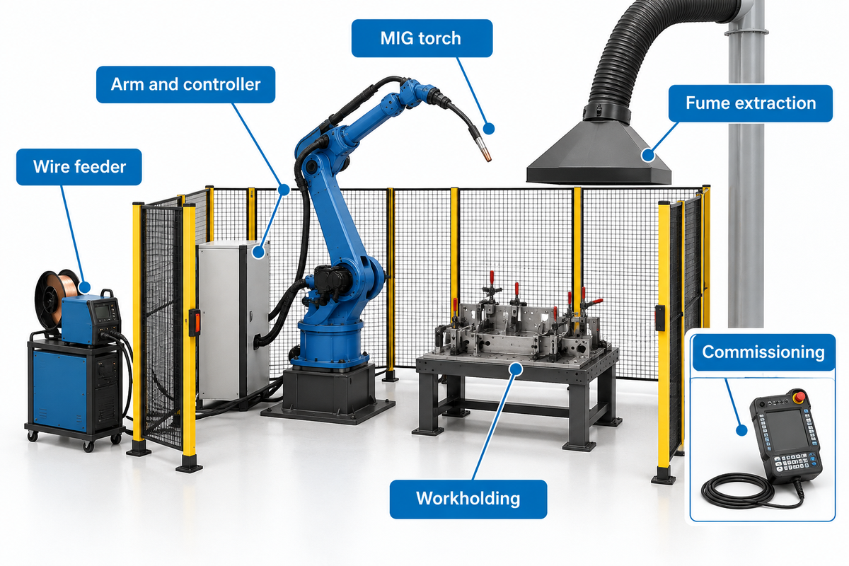
Hirebotics lists a US starting price of $105,000 for its Cobot Welder. The package it described included a Universal Robots arm, a Miller Auto Deltaweld power source, an air-cooled MIG torch and a cart. Hirebotics lists seam-tracking software and a rotary kit as options. For your plant budget, compare the base package price with a separate installed quote that itemizes the options you plan to use.
| Cost category | Ask each bidder to identify | Cost that can sit outside the headline price |
|---|---|---|
| Welding equipment | Arm, controller, feeder, torch, cables and cooling. | Options needed for the specified duty or material. |
| Workholding and motion | Number of fixtures, clamps and any coordinated external axis. | Tooling for the next family and engineering changes. |
| Site integration | Electrical supply, extraction, safeguarding and commissioning owner. | Site labor, installation and validation. |
| Release to production | First program, acceptance trial, training, software and support. | Recurring licenses, travel and additional programs. |
| Fume extraction | Hood location and required airflow at the torch. | Ducting, filters and airflow verification. |
| Part handling | How heavy assemblies arrive at the fixture. | Hoist, slings and operator loading time. |
| Seam sensing | Joint type and variation the sensor can measure. | Sensor mounting, calibration and program changes. |
| Replacement parts | Tips, liners and cables with reorder references. | Wear parts consumed before the next planned service. |
| Program ownership | Who can retrieve and edit the released program. | Training, backups and software access after handover. |
Leave the line open in the proposal until the bidder assigns responsibility for that work. When one proposal includes the first fixture and another offers a bare table, procurement can compare the totals only after adding the missing scope. For a used industrial robot, ask who will support the controller and welding interface and how the complete cell will be shown.
Compare robotic welding solutions on an itemized basis. Separate the initial investment from ongoing service costs. A welding automation bid may bundle programming software with the cell. Another bid may list separate charges for extra seats or training. Have the people who will maintain the robotic welding system check which software access the contract includes.
Ask for the payload worksheet too. Aubrik cites a payload range of 3 to 20 kg across its machines and gives a roughly 3 kg MIG torch as an example. Evsrobot lists its QJR6S-1 small-part unit with a 6 kg payload and a reach of 750.6 mm. For either case, the integrator needs to weigh the fully dressed torch and check the allowable wrist moment before finalizing the arm selection.
Run a sample-part trial before ordering
Agree on acceptance criteria for the sample welds with the supplier before shipping the parts. Send production parts, including the difficult revision and the extremes your incoming inspection usually accepts. Use the actual tack sequence, fixtures, wire and gas. Identify the welds the drawing requires and who can approve the results. Production sample approval and any contractually required welding procedure qualification need separate records.
Part-family acceptance sheet
| Record for each sample | Evidence to keep |
|---|---|
| Part and fixture identity | Drawing revision, lot, clamp state, loading direction and tack positions. |
| Joint condition and access | Location against the datum, root opening, torch clearance and any repositioning. |
| Time and result | Elapsed load-to-release time, first-pass result, rework and final disposition. |
| Release | Inspection method, acceptance criterion, exceptions and responsible person. |
| Consumables fitted | Wire grade and diameter, liner, drive roll and tip fitted for this run. |
| Thermal condition | Required preheat or interpass limits from the procedure and any interruption while waiting for the joint temperature. |
| Program identity | Controller revision, weld schedule and the operator authorized to release changes. |
| Joint measurement | Separate fixture location error from the opening between the mating edges on each sample. |
| Recovery after a stop | Reason for the stop, repair time, rejected piece disposition and who released the restart. |
Assume a trial takes 72 minutes from changeover through inspection. The team attempts nine pieces and accepts eight. This provides a measurement of 9 minutes per accepted piece. Dividing by all nine instead gives 8 minutes per attempt, which answers a different production question. For each part that’s returned for rework, count the time before accepting it.
Miller advises starting the trial below full speed. Miller gives a staged commissioning example with three or four initial pieces and another check at a 50% speed setting. Have the integrator identify what speed setting the test changes, and who’s authorized to make that change in the cell’s validated procedure. If the trial ends before the first contact-tip change, record that downtime as unobserved. To estimate full-shift productivity, extend the run time to include a tip change or include an additional maintenance allowance. Have the production team repeat the trial with the next part family and time how long it takes to retrieve the saved program. This shows what the team can reproduce after the demonstration crew leaves.
When measuring the benefits of robotic MIG welding compared to manual welding, give both operators the same inspection rule. A bid offering high-quality welds should identify the drawing or inspection criterion that defines an acceptable piece. Record the welding parameters for each repaired piece. This allows the next shift to repeat the welding tasks and investigate the cause of the rework.
When seam sensing earns its place
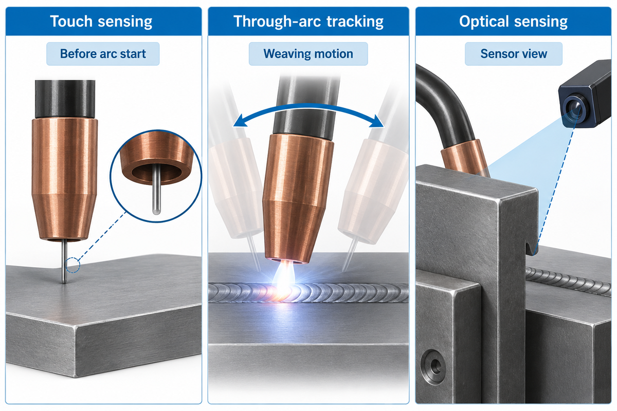
First record when and where the joint moves. If the starting position of the joint shifts as a unit from part to part, touch sensing may locate a reference before the arc starts. If the joint wanders during a given pass, consider using an active seam tracking process with the supplier. Locating the centerline still leaves a fit-up problem when the two parts open apart between clamps.
Wire touch sensing locates a conductive surface by touching it with a wire. Motoman lists two limitations for this method. First, its ability to detect joint gaps is limited, and second, it can’t find square butt joints. Through-arc tracking monitors the arc response during welding. The method that Motoman describes requires a weaving motion and thicker material. For optical sensing, check whether contamination or tooling obstructs the sensor’s view of the seam.
On the trial record, indicate the path programmed, what the sensor changed, and how the finished weld was accepted. If cleaning the locator restores joint position on repeated loads, add cleaning to the setup routine. Repair if wear or damage keeps the part from seating. If a sensor follows a shifting seam, but the part fails inspection, check the fit-up and welding process.
During the robotic arc welding trial, check whether the optical sensor keeps the seam in view throughout the arm’s turn. Ask the supplier to show the sensing option on the proposed MIG welding system with the actual joint coating and fixture. Record which faults stop the robotic welding process. Keep the fault log with the rejected part so the integrator can reproduce the problem.
Frequently asked questions
What are the downsides of robotic welding?
A welding robot needs a repeatable joint, access for the torch, a workable fixture and somebody who can release a changed program. In a mixed shop, programming and changeover can consume much of a short run. In a busy production line, the bottleneck may move to part supply or inspection. Try a normal order that includes a changeover and a difficult part, then count accepted pieces and record the hours spent correcting any rejects.
Can I use my existing MIG power source?
Yes, if the exact power-source model works with the feeder and the robot interface supports the control and feedback signals needed for automated starts, stops and fault handling. A power source that welds well by hand may still require an interface or different controls for automated starts, stops and fault handling. Have the supplier demonstrate arc initiation, communication after an interrupted cycle and recovery using the intended equipment before crediting a reuse saving.
How much does a MIG machine cost compared with a complete robot cell?
The US package in the cost comparison starts at $105,000 before the optional rotary kit and seam-tracking software. A standalone MIG machine and a robotic cell have different purchasing scopes. The machine supplies welding power and may include a feeder and torch. The complete system also needs motion, control, workholding and the equipment required to commission it at your site. Compare a current model-specific machine price with itemized cell quotations. For scale, the package price above includes the arm and process equipment, while some software and additional motion are priced separately by the supplier.
Who programs the next part?
Assign a trained program owner to make authorized changes for the next part and, if a shortage of skilled welders prompted the purchase, identify the welding professionals who can release those changes on each shift. Have that person retrieve the correct revision, check the fixture, make the authorized program change and obtain first-piece approval during acceptance. Agree who may edit weld parameters and who keeps a backup of the released program.
Can a welding cobot run while someone loads the next part?
Yes, but only if the installed weld cell layout, operating mode and validated safeguards permit that specific loading sequence while the cobot welds. When an operator loads a second fixture, the cell’s safeguards must protect the operator from arc radiation, spatter and contact with the arm or a moving positioner. Have the integrator demonstrate the intended loading sequence under the site’s approved risk assessment before building simultaneous loading into a production estimate.
To review a sample part, send Aubrik the weld drawing and fixture layout with the material, batch mix and acceptance criteria. Indicate the seam that gives your team the most trouble.
References & Sources
- American Welding Society’s GMAW guide
- Lincoln Electric’s aluminum wire feeding guide
- the original fillet-weld penetration study
- OSHA’s industrial robot system safety guidance
- Hirebotics’ US package pricing
- Miller’s welding automation trial guidance
- Yaskawa’s comparison of sensing methods
- ANSI, industrial robot safety standard revision
- The Fabricator, design objectives for robotic welding fixtures