Get in Touch with Aubrik Company

Updated July 2026 · Reviewed by the Aubrik (Wuxi ABK Machinery) technical team.
Welding rotator vs positioner is the equipment-selection question every fabrication shop eventually faces, and it shows up every time a job doesn’t fit last year’s fixture list. Both machines rotate a workpiece so the welder can hold one position while the arc does the work, but they accomplish that in radically different ways, and getting the selection wrong can cost far more than a wasted quote.
Quick Specs: Positioner vs Rotator
| Primary motion | Positioner: tilt + rotate (1–2 axes) | Rotator: rotate only (1 axis) |
| Typical capacity | 50 kg – 50,000 kg (custom) | 1,000 kg – 2,000 t (custom) |
| Best-fit geometry | Brackets, flanges, short or irregular parts | Long cylinders: pipe, tank, vessel shells |
| Workholding | Chuck, T-slot table, custom fixture | Powered rollers — no clamping |
| Typical buyers | Job shops, structural steel, robotic cells | Pressure vessels, wind towers, pipelines |
A welding positioner attaches a workpiece to a tilting table and moves it on one or two axes for tricky-angle access. A welding rotator, by contrast, lays a round workpiece on powered rollers and spins it on one fixed axis for long seams. They solve different geometry problems, not the same job at different prices.
Key Points
- Capacities for positioner and rotator overlap heavily in the 1-50t range. For parts in this weight class, workpiece configuration and center of gravity determine which machine best suited the application, not weight alone.
- The rotator’s drive rollers must comply with OSHA 1910.212 general machine guarding. For a positioner, the chuck (or for either machine, any frame that also serves as the return current) must comply with OSHA 1910.254.
- Search interest for “rotary welding positioner” is up 51 percent this year, following the increase in automated welding cells.
- No single source compares rotator and positioner pricing by capacity, so expect cost estimates from vendors to be only a general comparison.
What’s the Real Difference: Welding Positioner vs Rotator
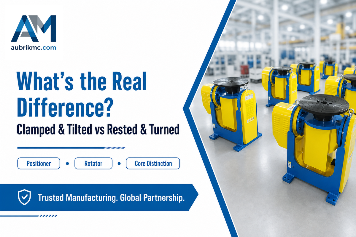
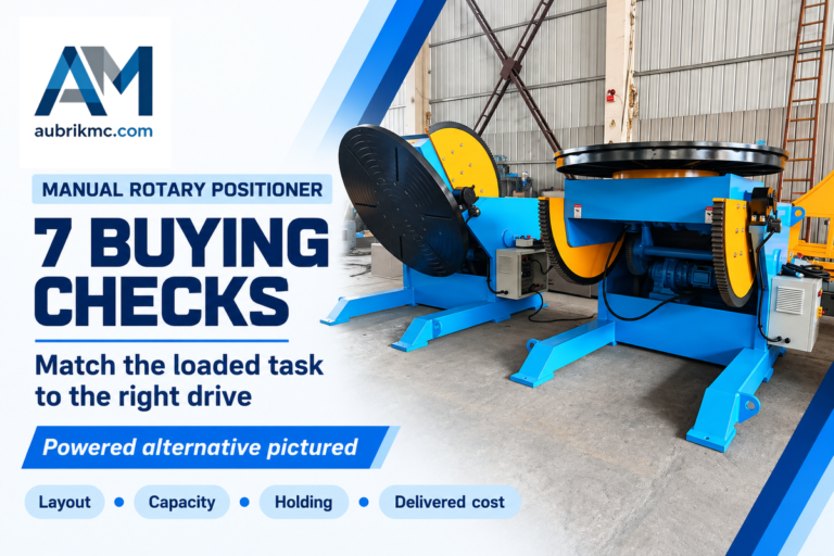
A welding positioner is a workholding machine: it clamps a part to a table, chuck, or fixture, then tilts and rotates it so the welder or robot reaches every joint in a flat, overhead, or vertical position for the best weld quality across manual welding and automated welding operations. A welding rotator does the inverse: it rests a cylindrical workpiece on powered rollers and turns it by friction, with no clamping at all.
💡 The Clamp-or-Rest Test
That single difference between “clamped and tilted” and “rested and turned” separates almost everything in this article, from capacity and cost to the safety review you’ll need across nearly every welding application this positioning equipment supports. Make a key decision. Before pulling out your spec sheets, ask this simple question: Does the joint require you to clamp and tilt the workpiece, or does the part just need to rest and turn?
Clamped-and-tilted calls for a positioner; rested-and-turning points to a rotator. This single question typically bypasses the discussion about capacity and cost and eliminates one type of machine altogether. As the decision matrix below details, it’s the ultimate deciding factor.
Use the correct terminology on the shop floor, deliberately. The word “rotator” is frequently used interchangeably with “positioner” out of habit, and that habit is exactly what leads to ordering the wrong type of machine.
Between them sits a third category: a column-and-boom welding manipulator moves the welding torch itself rather than the workpiece, and it’s usually paired with a rotator or positioner rather than replacing one. When the job needs the arc to travel along a joint on a stationary or lightly-fixtured part, a manipulator, not either machine in this guide, is probably the missing piece.
Motion & Geometry: Tilt-and-Clamp vs Rotate-and-Rest
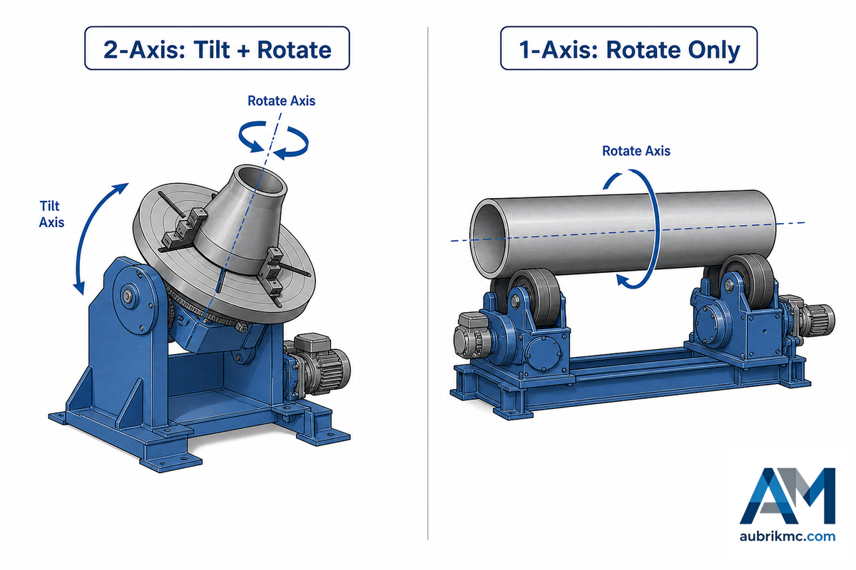
The rotary welding positioner operates in one axis for the table, but adds a second axis of tilt (making it, in the truest sense, a 2-axis positioner), meaning that no matter where a joint is on an irregular part, it will always be able to be presented horizontally. A rotator, on the other hand, only works on one axis: continuous rotation of the table through 360 degrees to rotate the workpiece about its own centerline, with no argument about presenting it flat since it never lifts off its resting line.
⚠️ Common Mistake
Guessing wrong on this axis question is a common and expensive mistake: a fabricator who fixtures an irregular bracket onto a rotator, because the shop’s floor is built around pipe and vessel production, ends up hand-tilting the part between passes anyway, which defeats the entire purpose of powered rotation and can add 20-30% to cycle time on a single job. Aubrik’s applications team sees this most often on retrofits, where a shop expanding from round-part work into bracket fabrication forgets to budget for the tilt axis a positioner adds.
Guessing wrong on this axis question is a common and expensive mistake: a fabricator who fixtures an irregular bracket onto a rotator, because the shop’s floor is built around pipe and vessel production, ends up hand-tilting the part between passes anyway, which defeats the entire purpose of powered rotation and can add 20-30% to cycle time on a single job. Aubrik’s applications team sees this most often on retrofits, where a shop expanding from round-part work into bracket fabrication forgets to budget for the tilt axis a positioner adds.
What is a rotary welding positioner?
Rotary welding positioners are positioners whose table indexes continuously instead of stepping incrementally, with tilt held constant or adjusted pass to pass under the same OSHA 1910.212 guarding scope as any other rotating table. Most of us would call this configuration a positioner without hesitation — it suits flanges, rings, or hubs needing a constant, predictable turn with no tilt variation for any given weld pass.
📊 Field Note
Shop-built rotators used for low-speed tig welding jobs generally have a minimum speed of around 0.05 to 0.3 RPM — that’s a turn every three to fifteen minutes, about as slow as the average welder can keep up with while feeding a filler rod and watching the weld pool to hold a perfect weld. When a quoted machine’s minimum speed sits well above that, ask for the usable range, not just the maximum RPM on the nameplate.
Shop-built rotators used for low-speed tig welding jobs generally have a minimum speed of around 0.05 to 0.3 RPM — that’s a turn every three to fifteen minutes, about as slow as the average welder can keep up with while feeding a filler rod and watching the weld pool to hold a perfect weld. When a quoted machine’s minimum speed sits well above that, ask for the usable range, not just the maximum RPM on the nameplate.
Positioner Types at a Glance
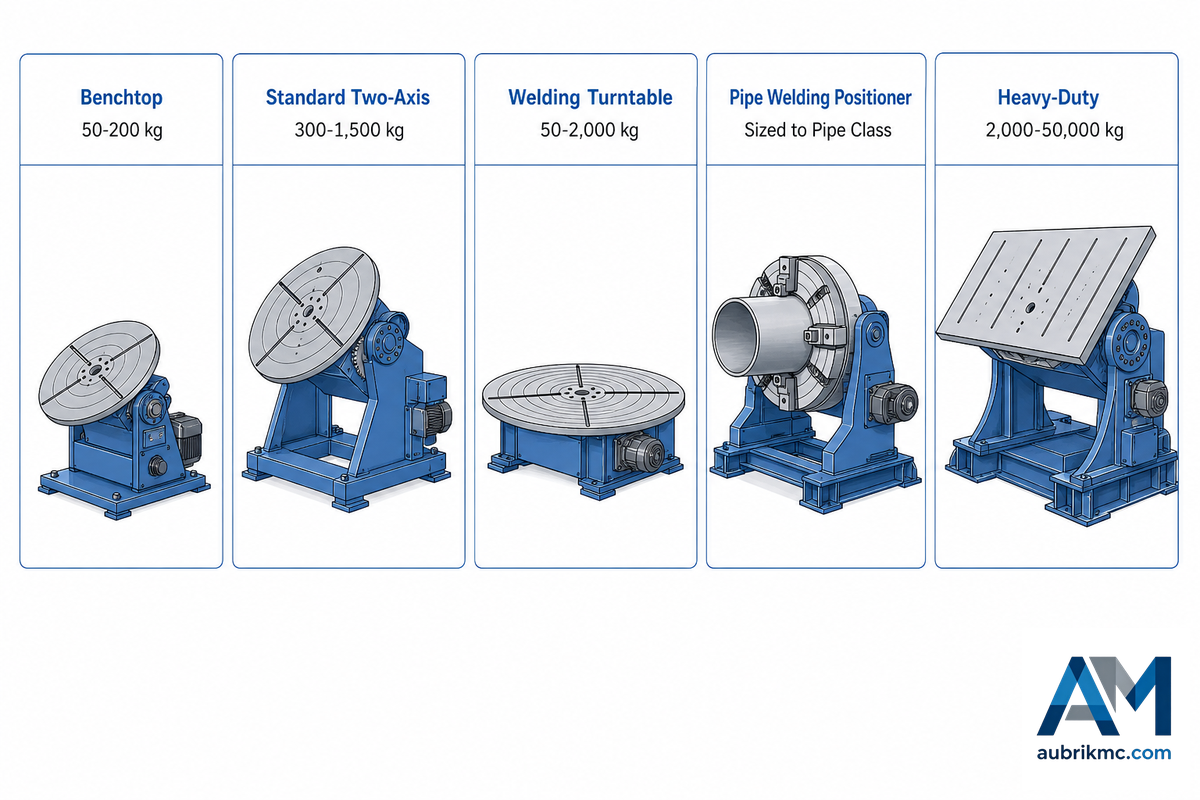
Not every positioner is an over-the-top heavy-duty unit, so just going by nameplate can get a user positioning equipment that’s far from adequate for the workpiece. Welding positioner design varies more than the name implies, and there are five general categories of these different types of welding positioners below to guide you through the entire variety of welding applications, from the bench top to heavy structural fabrication.
| Type | Capacity range | Best-fit work |
|---|---|---|
| Benchtop (manual welding positioner) | 50–200 kg | Small benchtop welding TIG parts, tube-to-flange work |
| Standard two-axis | 300–1,500 kg | Bracket and flange fabrication, bridge into semi-automated cells |
| Welding turntable (rotary table) | 50–2,000 kg | Rings, flanges, symmetrical parts needing steady rotation only |
| Pipe welding positioner (headstock-tailstock) | Sized to pipe diameter class | Pipe spools and flange assemblies needing chuck grip; also built as headstock tailstock positioner pairs for long tube welding shafts |
| Heavy-duty | 2,000–20,000 kg standard; to 50,000 kg custom | Pressure vessel heads, wind-tower flanges, structural weldments |
Picking by name alone, rather than by motion and capacity, is a mistake that shows up on the shop floor within the first week: a “standard two-axis” table ordered for what turns out to be a 1,800 kg bracket, 300 kg over its rated ceiling, because nobody checked the fixture weight, the welding positioner chuck rating, or the drive class (manual index vs. an automatic welding positioner with encoder feedback) against the class boundary. Full sizing specifics, including how fixture weight and center-of-gravity offset change the usable load, are covered in Aubrik’s heavy-duty positioner selection guide; this article focuses on the point where a positioner stops being the right answer.
Rotator & Turning-Roll Types at a Glance
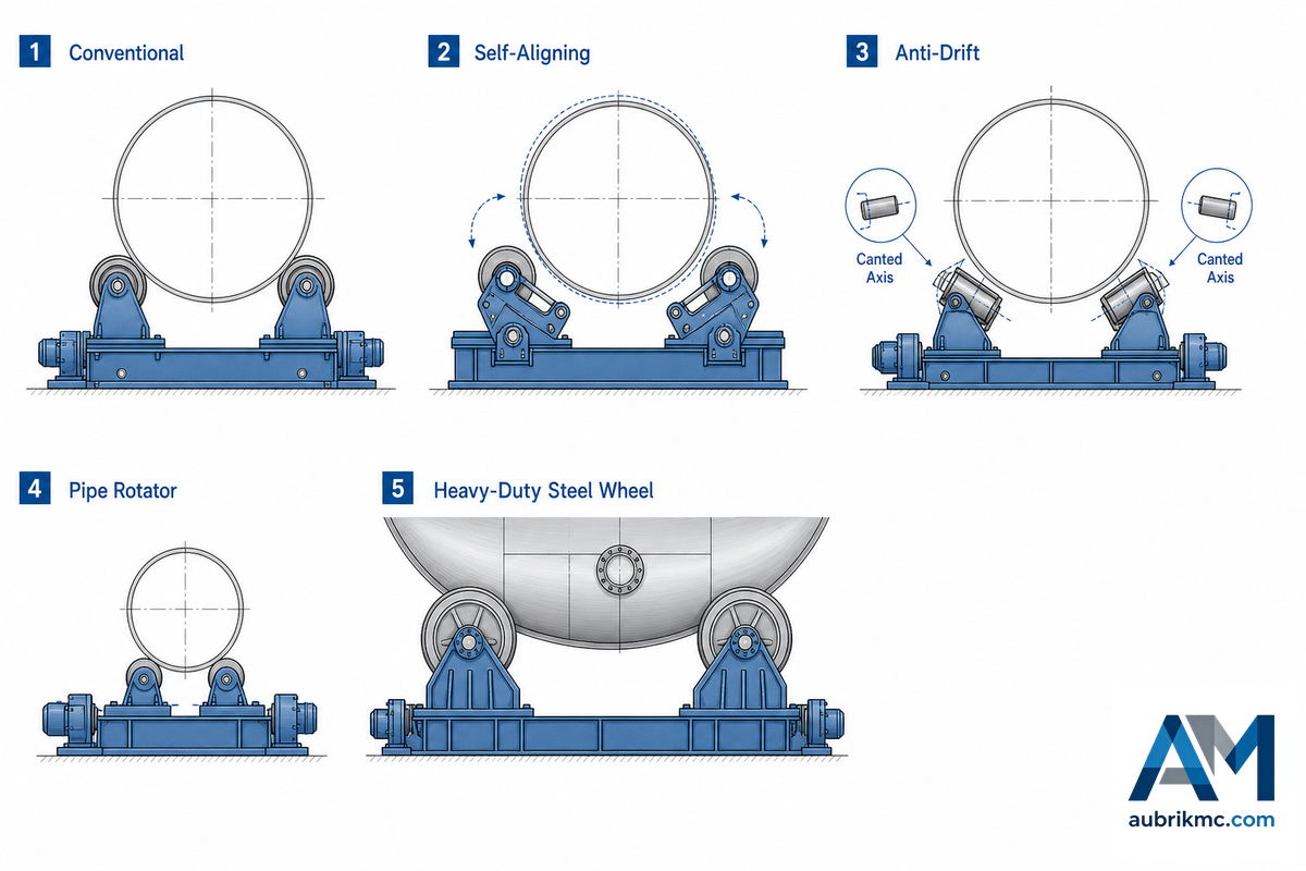
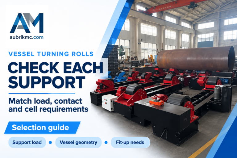
“welding rotator” and “turning rolls” are terms that identify the same general family of roller-based equipment, though “turning rolls” are the preferred nomenclature in shops specializing in tank and pressure vessel construction. Selection rests more on the workpiece’s diameter consistency and drift risk than on simple weight capacity for these heavy workpieces, since a bearing that supports the load in each roller is what lets the powered wheels rotate the workpiece by friction alone.
| Type | Mechanism | Best-fit work |
|---|---|---|
| Conventional | Manually set wheel spacing | Stable diameters, cost-sensitive runs |
| Self-aligning | Floating brackets track the diameter | Mixed or out-of-round shells |
| Anti-drift | Canted idler axes resist axial walk | Long, precision circumferential seams |
| Pipe rotator | Narrow-spaced rolls | Long pipe spools |
| Heavy-duty (steel wheel) | Steel rollers, standard 1–1,000 t; custom to 2,000 t | Extreme tonnage, near-arc heat |
This anti-drift geometry is old, well-documented engineering: US Patent 8,342,493 B2 describes canting the idler axles slightly oblique to the workpiece axis so they generate an opposing axial force against drift. Choosing a conventional rotator for an out-of-round shell is a common and costly mistake in the field, because even 2-3% ovality is enough to make the workpiece walk several centimeters off-track over a single pass, forcing a re-grind of the joint. Aubrik’s rotator and turning-roll engineering guide walks through that mechanism and the surface-speed math in full; this article won’t repeat it.
The Weight-Class Handoff Zone: When to Switch from Positioner to Rotator
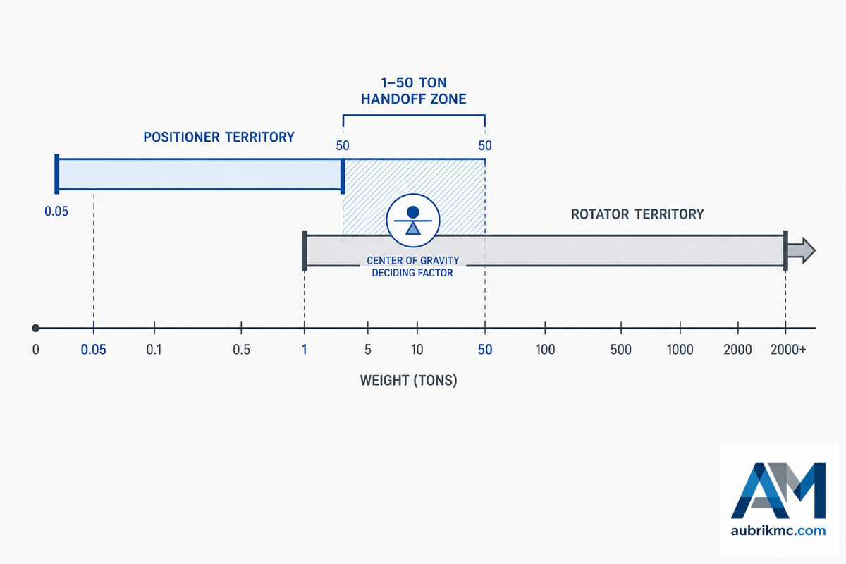
Most purchasing guides imply a clean weight line separates the two machines. It doesn’t: Aubrik’s own published ranges show a heavy-duty positioner scaling to 50,000 kg custom, while a standard rotator starts at roughly 1,000 kg, which means the 1 to 50 metric-ton band is genuinely shared territory, not a boundary.
The Weight-Class Handoff Zone
| Below ~1 t | Positioner territory — rotators rarely built this small; geometry usually needs tilt anyway. |
| 1–50 t (the handoff zone) | Both families are available. Decide by geometry and CG, not weight — see the worked example below. |
| Above ~50 t | Rotator territory — a positioner in this class would need an unusually large custom tilt drive; shells this size are rarely clamped to a faceplate. |
Inside that shared band, one factor decides it: where the center of gravity sits, not what the scale read. As a workpiece’s CG moves away from the positioner’s table face, it multiplies the torque the tilt drive has to resist. That’s the same eccentric-load physics the US Department of Energy’s Hoisting & Rigging Fundamentals documents for lifting gear, an off-center load can drastically cut a machine’s usable capacity versus a centered one.
📐 Engineering Note — Worked Example
Suppose we’re quoted a 3,000 kg pressure-vessel head with a 500 kg fixture attached (3,500 kg total) and a center of gravity 450 mm from the table face, offset 300 mm from the rotation centerline — typical heavy-fab RFQ numbers. By weight alone, that’s comfortably inside a heavy-duty positioner’s range. Run the Clamp-or-Rest Test anyway: does the joint need tilting to a new angle for root-pass access, or does it just need to turn?
Suppose we’re quoted a 3,000 kg pressure-vessel head with a 500 kg fixture attached (3,500 kg total) and a center of gravity 450 mm from the table face, offset 300 mm from the rotation centerline — typical heavy-fab RFQ numbers. By weight alone, that’s comfortably inside a heavy-duty positioner’s range. Run the Clamp-or-Rest Test anyway: does the joint need tilting to a new angle for root-pass access, or does it just need to turn?
Should the head need tilt, size the positioner against its load chart at that specific CG offset, not the nameplate maximum. A long shell section with no tilt requirement skips that review entirely — a rotator sized to the same 3.5 t never lifts the CG off-center in the first place.
Cost & Total Cost of Ownership Comparison
Beware any site offering one single number for “welding rotator vs positioner price” — there’s no such same-capacity, apples-to-apples comparison published anywhere, and this guide isn’t going to invent one. Typical figures start somewhere around $50,000 for an engineered rotary positioner from an industrial supplier, again, this is from one specific vendor’s blog, take it as a directional starting point, not a market average. What really moves the needle up or down for either machine, and whether it will increase productivity on your specific welding project, comes down to one short list of drivers.
- Rated capacity and, for positioners, the tilt-torque class at that capacity
- Speed-control precision, open-loop AC drives cost less than closed-loop encoder or servo control
- Custom fixturing or chuck tooling relative to a catalog table
- Robotic-cell interface readiness (repeatable fixture points, signal access)
⚠️ Common Mistake
Buyers who skip the pricing caveat above and compare a $12,000 benchtop turntable quote against a $50,000 heavy-duty positioner quote, assuming they’re shopping the same product, make an expensive apples-to-oranges mistake before the RFQ even goes out.
Buyers who skip the pricing caveat above and compare a $12,000 benchtop turntable quote against a $50,000 heavy-duty positioner quote, assuming they’re shopping the same product, make an expensive apples-to-oranges mistake before the RFQ even goes out.
For total cost of ownership, the honest comparison isn’t machine price, it’s cycle-time impact for your specific part mix, plus whatever it costs to close any OSHA 1910.212 guarding gap out of the box rather than as a retrofit later. Rotators carry fewer moving axes and typically a smaller maintenance footprint than a positioner’s tilt gearbox and chuck assembly, but that advantage only show up if your parts are actually round enough to skip the tilt axis. Ask any quoting supplier for usable load at your real center-of-gravity offset, not just a headline capacity number, that single question, more than any spec sheet, separates a supplier acting as a consultant from one just moving a catalog item.
Which Industry Needs Which?
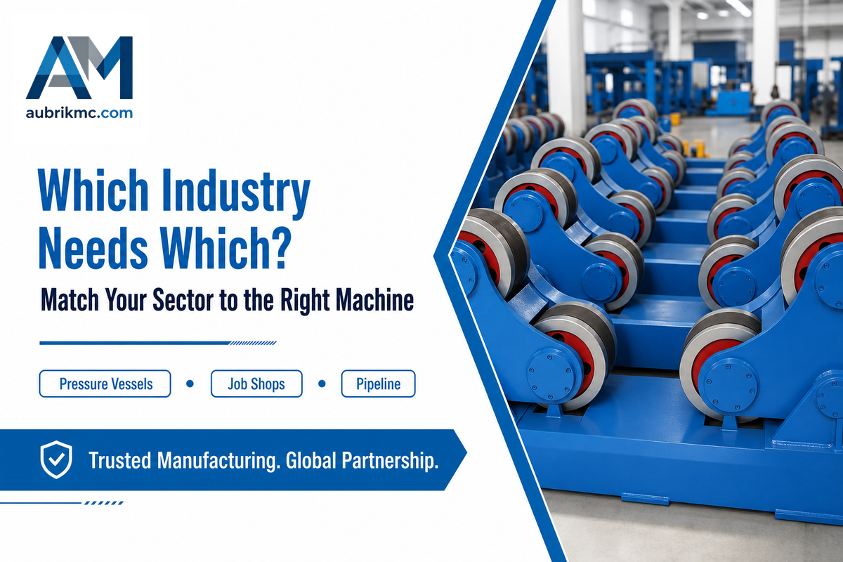
Industry pattern is quicker than a spec-sheet analysis when you’re winnowing options before an RFQ, and it heads off the classic mistake of specifying against the wrong default for your sector. Pressure-vessel and pipeline shops default to rotators; job shops and structural fabricators default to positioners — the table below breaks down five common industry and part-family patterns against their typical machine choice.
| Industry / part family | Typical default |
|---|---|
| Pressure vessels, boilers, tanks | Rotator — long shell, no tilt needed |
| Wind tower and large pipeline sections | Rotator, often paired with a manipulator |
| Pipe spools, flanges under ~2 t | Positioner (chuck-mounted) — size drives the split |
| Structural steel brackets, job-shop repair | Positioner — irregular geometry needs tilt |
| Robotic welding cell integration | Positioner as the coordinated axis; rotator when the part is a long cylinder |
Trade press confirms the robotic pattern directly: a case documented by The Fabricator describes a structural-beam cell where the beam moves directly to a station that holds the workpiece and indexes it while a robot is welding every joint; the positioner functions as a coordinated axis of the robot, not a standalone table, and supports continuous loading and unloading so the next beam is staged the moment one finishes.
Grounding & Guarding: The Safety Gap Between the Two Machines
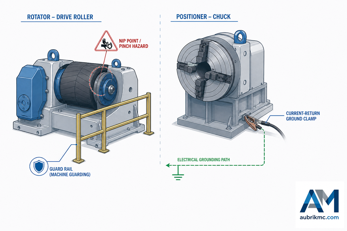
And don’t fall into the trap of thinking there’s a single standard for rotators and a different one for positioners – either standard can apply to either machine, depending on configuration. 1910.212 (general machine guarding) applies to any machine with “point of operation, ingoing nip points, rotating parts, flying chips and sparks,” which is also why manual handling near an unguarded roller raises the likelihood of weld defects along with the injury risk, since a slip that nudges alignment mid-pass hits both at once. Thus, the uncovered drive rollers on a rotator are just as susceptible to this regulation as the rotating table of a positioner, and 1910.254 separately demands ground connections for current carrying welding current to be “mechanically strong and electrically adequate,” with requirements extending to “any structure, fixture, or conveyor… which is used as a part of the current-return circuit.”
⚠️ Important
Don’t make assumptions regarding the grounding system for your particular machine type – ask the supplier what scheme is intended for your application. When it’s in the design-build plan that the robotic-welding cell is next up on the design list, then know that the robotic arc-welding robot and related systems and equipment will fall into their own standards layer – AWS D16.1M. Then it can be part of the discussion once the positioner or rotator has been specified for the cell.
3 Common Buying Mistakes That Hit Both Sides of the Aisle
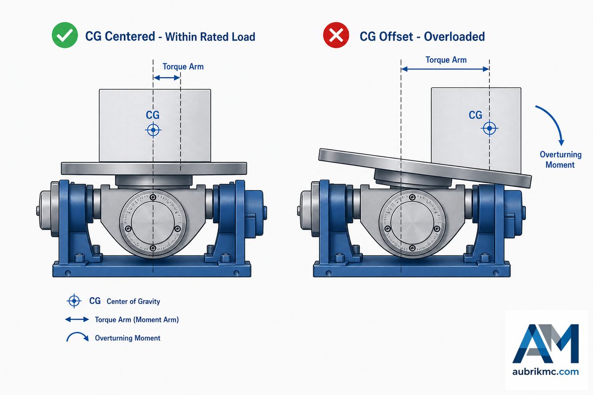
Errors on these two machines run in both directions-towards the apparent capacity error and toward a more-rarely talked about tendency to defaulting to the more-complicated machine when a simpler one would work much faster. Shops using welding positioners for years sometimes forget that not every job calls for one; a welding clamp on a basic welding table is occasionally the right, cheaper answer when a part doesn’t need powered rotation at all. The center-of-gravity mistake in the table below traces back to the same eccentric-load physics the US Department of Energy’s Hoisting & Rigging Fundamentals documents for lifting gear.
| Mistake | Consequence | Better RFQ question |
|---|---|---|
| Sizing a positioner by rated load alone, ignoring center of gravity | A 5-ton-rated table can still be overloaded by a 3-ton part if the fixture pushes the CG far enough off center — torque, not raw weight, breaks a tilt drive | What is usable load at my actual CG offset, not just the nameplate maximum? |
| Defaulting to a tilt positioner for round or nozzle-shaped parts out of habit | Turning rolls would let the arc lay a continuous bead without repositioning between passes — a real welder’s account of nickel-alloy nozzle work put it plainly: rollers bring the joint to the welder in one pass, a tilt positioner forces stop-and-reposition | Does this part actually need a tilt-angle change mid-weld, or just continuous rotation? |
| Buying on price and getting unstable low-speed control | A drive that “spins slowly” unloaded can lose 2–5% of that speed once the real workpiece is on the table | What is the usable low-speed range under load, confirmed on my actual part? |
Industry Outlook: Automation & the Rotary-Positioner Growth Curve
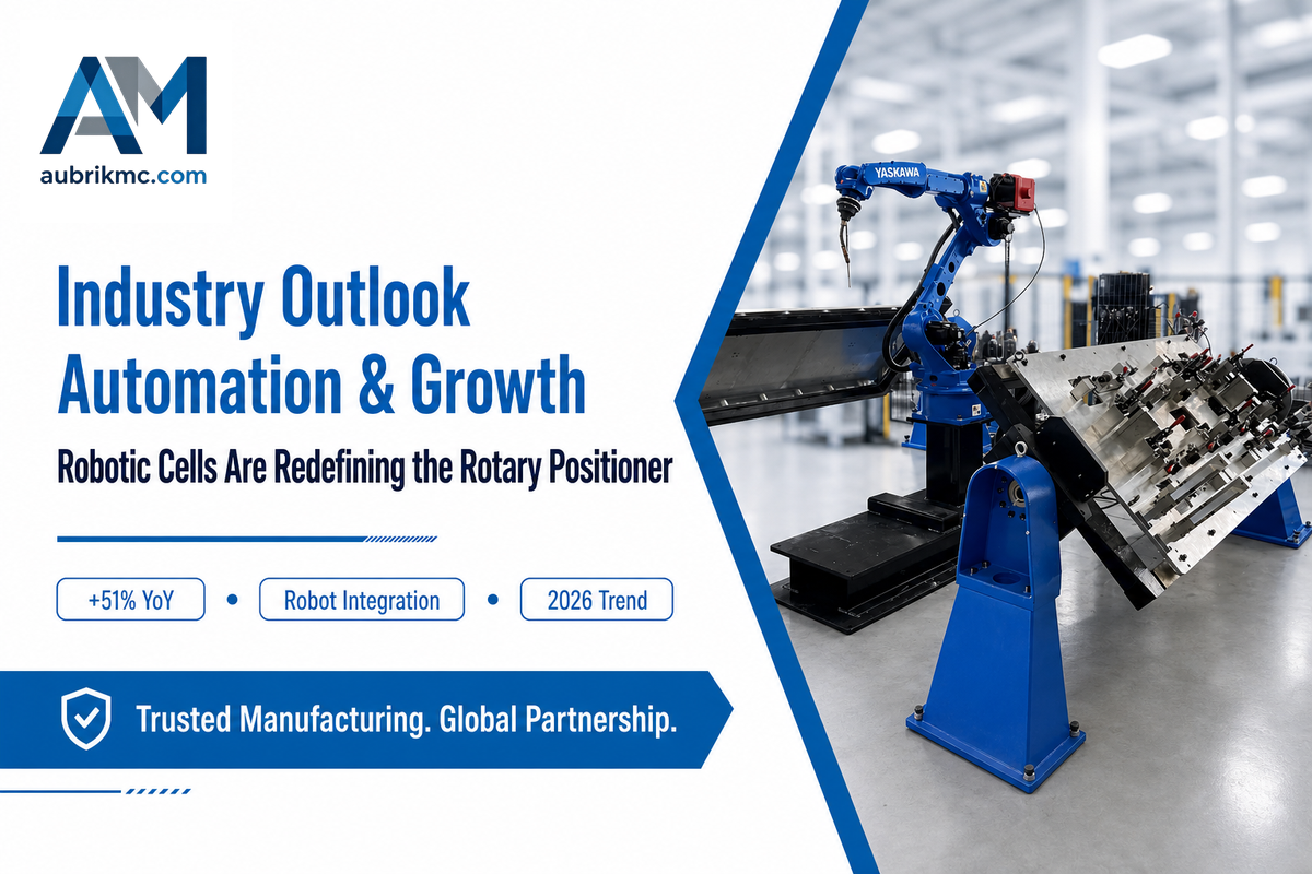
Robotic-cell integration is the driver worth watching here, not just some vague “the industry is automating.” Demand for the configuration most commonly paired with a robot arm as a coordinated axis — “rotary welding positioner” — has grown 51% year over year as of mid-2026, against stagnant-to-declining growth for “welding positioner” more broadly. Take market-size estimates with a grain of salt: the overall industrial robot installed base keeps growing (542,000 units installed in 2024 per the IFR World Robotics 2025 report, the fourth straight year above 500,000 units), but country-level sector mix shifts year to year, so a single robot-installation statistic doesn’t by itself prove welding-cell demand.
“Our engineering team frames it simply: if the workpiece needs to change angle mid-weld, it goes on a positioner. If it just needs to keep turning, it goes on rollers. Everything else in the spec sheet is downstream of that one answer.”
— Aubrik Engineering Team
Skipping that step is a costly mistake Aubrik’s applications team sees repeatedly: a shop that buys a bare-bones positioner today, because the upfront price runs 10-15% lower without encoder feedback, often pays for a full control retrofit within two years once a robot arm joins the production line. If the current purchasing plan is a simple tabletop machine for 2026, the smart choice now is to call out automation readiness up front, as stable, low-speed rotation under load, consistent fixturing locators, and an uncluttered control interface cost relatively little up-front and are prohibitively costly to add later with the robot arm.
Which Should You Choose? Decision Framework
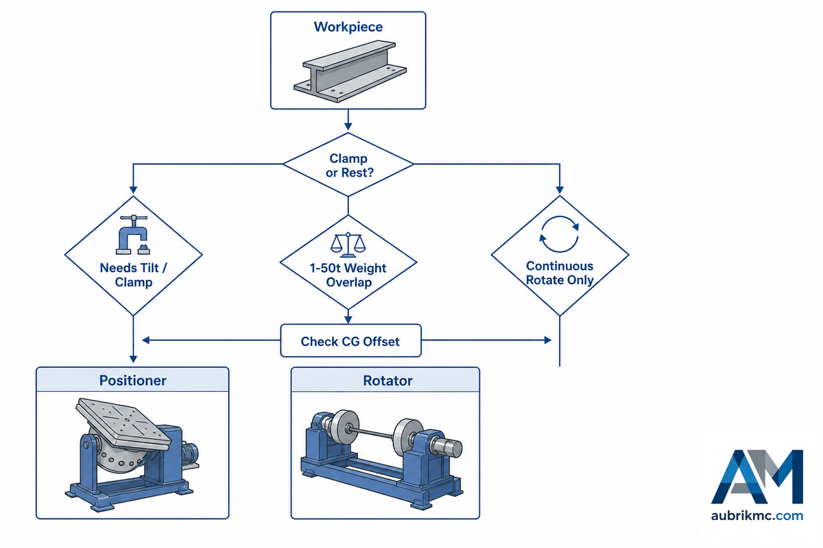
Skipping this checklist is the single most expensive mistake in this whole guide, because a wrongly specified machine gets discovered only after the workpiece is on the floor and the fixture is bolted down — a rework and re-order cycle that can cost weeks, not just a change order. Aubrik’s own RFQ intake catches this at the geometry-and-CG question, not the weight question, in roughly nine cases out of ten.
The 10-Type Machine Reference Table
Every positioner and rotator subtype covered above, side by side in one place — the single table this guide exists to provide, since no other page compares both machine families at once.
| Type | Family | Capacity / mechanism | Best-fit work |
|---|---|---|---|
| Benchtop | Positioner | 50–200 kg | Small TIG parts, tube-to-flange work |
| Standard two-axis | Positioner | 300–1,500 kg | Bracket and flange fabrication |
| Welding turntable | Positioner | 50–2,000 kg | Rings, flanges, steady rotation only |
| Pipe welding positioner | Positioner | Sized to pipe class | Pipe spools, flange assemblies |
| Heavy-duty | Positioner | 2,000–50,000 kg | Pressure vessel heads, wind-tower flanges |
| Conventional | Rotator | Manual wheel spacing | Stable diameters, cost-sensitive runs |
| Self-aligning | Rotator | Floating brackets | Mixed or out-of-round shells |
| Anti-drift | Rotator | Canted idler axes | Long precision circumferential seams |
| Pipe rotator | Rotator | Narrow-spaced rolls | Long pipe spools |
| Heavy-duty (steel wheel) | Rotator | 1–2,000 t | Extreme tonnage, near-arc heat |
Machine-Family Decision Table
- Part is round or cylindrical, no tilt-angle change needed mid-weld → Rotator.
- Part is irregular, bracketed, or needs the joint presented at a new angle → Positioner.
- Weight falls in the 1 to 50 ton hand-off range, and geometry is uncertain – verify center of gravity offset against the supplier’s load chart before choosing either machine.
- The part will enter a robotic cell as a coordinated axis, and needs to be designed from day one to accommodate the positioner with the necessary signal access and repeatable mounting points.
- Still unsure after all four checks → run your exact weight, diameter, and tilt requirement through Aubrik’s interactive rotator vs. positioner selector for a structured recommendation.
For a deeper look at either machine family on its own terms, full sizing math, wheel materials, and standards detail, see Aubrik’s welding positioners range and welding rotators and turning rolls range.
Frequently Asked Questions
Q: What is the difference between a welding positioner and a welding rotator?
View Answer
A welding positioner clamps a workpiece — usually a cylinder but also irregular shapes — to a table, chuck, or fixture and moves it on one or two axes, presenting an irregular or angled joint flat for welding. Its counterpart, the welding rotator, rests a round or cylindrical part on powered rollers, rotating it about a single, stationary axis without clamping or tilt at all. Follow the “Clamp-or-Rest” test from earlier in this article: if the part requires a changing angle in the weld, you’ll want a positioner; if it just needs to rotate continuously, the simpler and less expensive rotator will suffice. Larger plants with mixed part families might use both machines to specialize lines for distinct part types-perhaps running rotators for their pressure-vessel shell work and positioners for structural brackets-rather than trying to force one machine to handle everything.
Q: What is the difference between a welding positioner and a welding fixture?
View Answer
Welding fixtures hold the actual workpiece that’s being manipulated by the welding positioner. Fixtures are custom-designed to hold a specific workpiece shape and can include locating pins, clamps, a welded plate, or even a 3-jaw chuck built to conform to a specific part family. While the welding positioner does the actual movement, providing rotation and tilt, it mounts on a table and is driven by the machine’s motion system; if the fixture doesn’t rigidly secure the workpiece, the positioner can’t compensate and achieve the necessary repeatable precision.
Q: Can a fabrication shop use both a positioner and a rotator together?
View Answer
Yes. Large, multi-line shops frequently use both machines. Usually, these shops are working with a mix of part types and are not using one machine for all jobs on the same part, but rather segregating the work by part geometry. A pressure vessel fabricator, for example, might use rotator lines for their long cylinders and a positioner cell for irregular shapes like structural brackets. If you have a genuine mix of long-cylindrical parts and irregular bracket-style parts, investing in both from the beginning often makes sense and saves cost over selecting a machine that will be underperforming for at least one of those categories.
Q: How much does a welding rotator cost compared to a welding positioner?
View Answer
Since no published source makes direct comparisons between Rotator and positioner prices at equivalent capacities, assume any number you see is a directional indicator rather than a market reference. Industrial rotary positioners are generally priced starting at about $50,000 for a fully engineered machine from at least one manufacturer. Rotators can start at a lower price for a lightweight pipe-work setup (they don’t need a tilt gearbox or chuck), but prices will increase significantly for complex custom vessel-handling systems. A positioner used to hold and rotate a part in position to weld it commands a price premium over a rotator at the same capacity, precisely because positioners are commonly used with extra tilt-axis hardware a rotator skips entirely. Get a quote at the capacity you actually need and with the required control precision, not a catalogue starting point.
Q: What size or weight of workpiece needs a rotator instead of a positioner?
View Answer
There’s no one-size-fits-all chart for weight – there’s considerable overlap between capabilities, typically from 1 to 50 tons in weight range. Above this, Rotators dominate; below it, positioners are preferred. In between, your decision comes down to your part’s geometry and the placement of its centre of gravity (CG), not the number on the scales.
Q: Should I buy a welding manipulator instead of either one?
View Answer
Yes, if you need to move the torch around the part – not the part around the torch. A column-and-boom manipulator can hold the welding torch on a stationary or lightly fixtured part and traverse it along a weld seam (e.g., submerged arc welding using a rotator for the vessel and the boom to keep the wire steady over the seam). This setup allows the welder to stay focused on arc quality on stationary parts while the robot or boom handles travel, a common pairing in submerged-arc welding operations on long vessel seams. However, if the workpiece itself must rotate or tilt, you’ll still need a Rotator or positioner below it to accomplish this.
Q: Are there drawbacks to welding positioners?
View Answer
Yes, and it’s wise to be upfront about them as they impact your decision-making. A positioner’s combined tilt and rotate action is inherently more complex mechanically than a Rotator’s roller-bearing setup, and positioners also tend to be large and heavy pieces of shop equipment in their own right. This generally results in higher purchase prices, more extensive maintenance requirements (gearbox, chuck, tilt-actuator), and a higher risk of overload if CG information isn’t included in the machine specification – the unit can be rated for weight but overloaded if the CG offset is excessive due to a skewed fixture. That complexity is exactly why welding positioners are specialized rather than general-purpose machines: a positioner allows any weld joint to be presented at the optimal angle for welding — flat, overhead, or vertical — which is what welding positioners enable that a rotator physically cannot; positioners can also cut cycle time on multi-joint parts even after accounting for the added mechanical cost. This doesn’t mean positioners are not suitable; it means that CG information must be factored into the capacity sizing calculation.
Why We Write This
We’ve manufactured both welding positioners and Rotators at Aubrik (Wuxi ABK Machinery) since 1999 and have regularly encountered buyers who assume the two are synonymous names for a similar type of welding positioner. The correct choice hinges on your part and processing needs, not an arbitrary weight designation — picking the right welding positioner or rotator lets a shop improve weld quality and deliver high-quality welds from the first article, not the hundredth. Reviewed by the Aubrik technical team.
References & Sources
- 29 CFR 1910.212, General requirements for all machinesOccupational Safety and Health Administration
- 29 CFR 1910.254, Arc welding and cuttingOccupational Safety and Health Administration
- Hoisting & Rigging FundamentalsU.S. Department of Energy
- World Robotics 2025, Industrial Robots (Executive Summary)International Federation of Robotics
- ISO 17662:2025, Calibration, verification and validation of welding equipmentInternational Organization for Standardization
- US 8,342,493 B2, Anti-drift turning roll systemUSPTO
- Structural beam welding automation, no programming requiredThe Fabricator
Related Articles
- Welding Rotators & Turning Rolls: 2026 Engineering Guidedrive design, surface-speed math, and drift physics in full
- Welding Positioners & Turntables: Selection Guidethe full positioner-family selection walkthrough
- Heavy Duty Welding Positioner: Capacity, Tilt and RPM Guidemoment-load sizing for the largest positioner class
- Pipe Rotator for Welding: The Operating Guidesizing and operating a dedicated pipe rotator
- Aubrik Robotic Welding Systemswhere positioners and rotators fit inside a robotic cell