Get in Touch with Aubrik Company

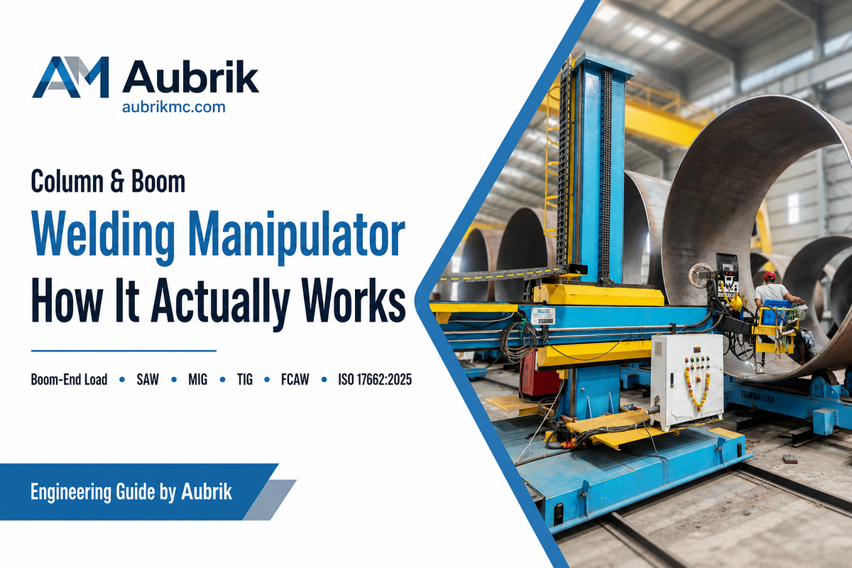
A column and boom welding manipulator is a machine that moves the torch over the joint at a consistent speed via a boom, instead of the operator hand-holding the torch and walking with it.
Quick Specs: Column and Boom Welding Manipulator
| Boom-end load capacity | ~7 kg (portable) to 600 kg+ (heavy duty), depending on model tier and mounting point |
| Column / boom stroke | Roughly 1–5 m per model class (published ranges run 42–192 in on common lineups) |
| Travel speed | 5–120 in/min (127–3,048 mm/min), variable-speed AC or servo drive |
| Supported processes | SAW, MIG/GMAW, TIG/GTAW, FCAW — single or dual-process heads |
| Arc-on time | ~10–25% manual/semi-automatic vs. approaching 100% for fully automated SAW. |
A column-and-boom welding manipulator keeps the torch on the joint while the column sets height and the boom sets reach. Specify the weld length, torch package, travel speed, working envelope, rail or floor arrangement and the load case before choosing a model. The acceptance list should also state seam tracking, operator access, interlocks and how the manipulator interfaces with the positioner.
In short
- A manipulator moves the torch, whereas a positioner or a rotator moves the workpiece, and most shops working with heavy materials eventually end up owning both.
- Load capacities of booms are location specific: AMET’s spec sheet only adds 50kg of capacity when the load is on the opposite end of the boom compared to being placed in the middle.
- The widely-quoted claim that “automation doubles or triples arc on time” is true directionally but generally exaggerated. Independently sourced data puts the real range closer to 10 to 25 percent for a manually welded application, compared to a SAW welding operation running almost 100% once fully automated.
- The new ISO 17662:2025 standard just published makes very little change, if any, and it’s focused on calibration rather than the design itself, contrary to the impression created by its ‘new edition’ title.
What a Column and Boom Welding Manipulator Actually Does
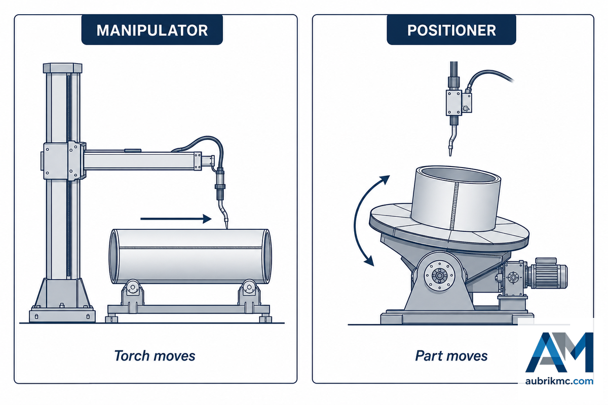
Column and boom welding manipulators feature a welding head that travels along the weld seam on a horizontal boom that moves up and down a vertical column.
This head travels at a constant speed while the workpiece may remain stationary or rotate on a device positioned beneath the column and boom. Moving the head, not the part, is the key differentiator between a column and boom and a positioner.
Although often referred to by various terms across the welding industry, every column and boom manipulator system performs the same function in welding applications: freeing the torch from manual operation and positioning it in a way that eliminates the need for constant operator intervention on long weld runs. One practitioner on the eng-tips.com forums pointed out to a novice engineer, in a real thread from 2010, that an arc manipulator like this “welding manipulator… consist of a single column with a radial arm or gantry that holds the welding head,” making it distinct from a positioner. Separately, a byline in a trade journal from a Lincoln Electric Canada marketing manager states plainly that a “welding manipulator” – what most customers looking for a column and boom welding machine or manipulator welding equipment are actually searching for – “is also called a column and boom, side beam, or gantry system,” and is the “standard mechanized automation form” for heavy industries like oil and gas, pressure vessels, shipbuilding, and structural steel, as opposed to a six-axis robot used in high-mix, low-volume automotive production.
Manipulator vs. Positioner vs. Rotator, Who Moves, Torch or Part?
Manipulator
Moves the torch along the seam. Part usually stays put or turns on separate equipment.
Positioner / Rotator
Moves the part — rotates or tilts it under a torch that stays fixed.
In reality most heavy fab shops own both since each machine answers a different question: A manipulator asks “How do I move the welding head down a 30 foot seam without a human having to walk with it?” A positioner answers “How do I rotate a round thing so that the seam lays flat on the ground beneath a stationary torch?”. One alone can’t do the job: A manipulator can’t rotate a wind tower can, and a positioner alone can’t traverse 20 feet down a wind tower can. For more about the guts of the second machine, see Aubrik’s welding positioner and welding rotator & turning rolls buying guides.
Inside the Machine: Column, Boom, Trolley & Control System
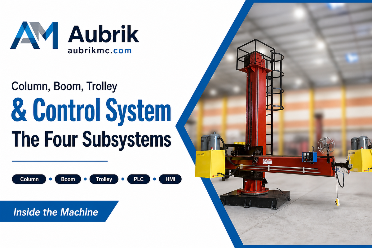
Four systems make the real weld at any column and boom: a column which controls the height of the work, a boom which controls the horizontal reach of the welding head, an optional motorized trolley, (often called a traveling car on a railed welding station), which moves the entire assembly along a rail to perform repeat seams, and a control system — anything from a simple pendant up to a full PLC/HMI — which sets travel speed through the operator controls for the whole cell. Make one mistake in any of these four, and you’ll see the result on the bead, not on the spec sheet; a drifting torch is really a welding head stability problem on the travel axis.
| Subsystem | Function | Symptom if wrong |
|---|---|---|
| Column | Sets working height, carries vertical load | Insufficient clearance over the part; cantilever loading on the base |
| Boom | Sets horizontal reach, holds the torch rigid | Deflection under load → torch drifts off the joint mid-pass |
| Trolley (rail-mounted) | Indexes the assembly between long seams | Manual repositioning eats the time the manipulator was bought to save |
| Control system (pendant/PLC/HMI) | Sets and holds travel speed, sequences multi-process recipes | Open-loop drives lose speed under load; no repeatable, auditable travel-speed record |
This four-system approach carries through Aubrik’s own column and boom welding manipulator model lineup, scaled in a manner that grows both columns and booms equally.
This tension between coarse position and fine speed is implicitly being purchased with any column and boom, as a real, patented design shows: EP4347177B1, “Welding boom,” Mv Welding Oy, Finland, 2025. The design incorporates a two-stage locking mechanism which allows a user to manually push a boom to the starting point and then engage a separate self-locking mechanism to drive the boom along the seam at controlled speeds, in part because the “slow and laborious” process of pre-weld adjustment for previous booms makes them “unsuitable for a productive workshop.”
The Boom-End Load Stack, Why Buyers Under-Size the Boom
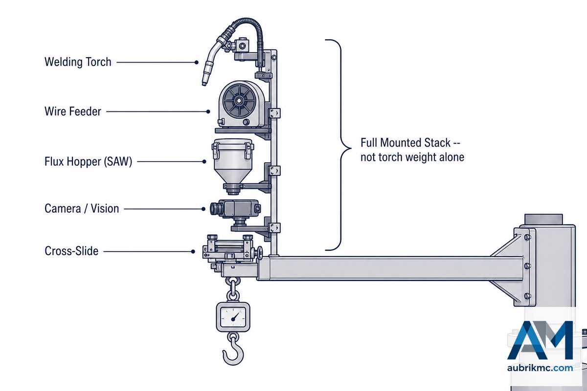
Boom-end load capacity refers to the greatest amount of weight that a boom can support at its working extension while maintaining torch positioning, and the figure displayed on a spec sheet isn’t universal across the boom’s reach. Koike’s own manipulator-sizing guide lines articulate the point explicitly: “manipulator load capacity should take into account all added weight, not just the welding head,” noting that operators frequently fail to add line items such as operator platforms and cross slides-a single operator platform can add many pounds once handrails and a safe working deck are counted. AMET’s own spec sheet supports the argument with a specific location-based illustration: maximum lift capacity of a manipulator is equal to its rated boom capacity plus an additional 50 kg (110 lbs)-but only if that added weight is placed at the opposite end of the boom. If you spec a 600-kg machine, assuming the figure accounts for a torch, feeder, flux hopper, and camera working at the boom’s working end, your available working margin will be less than you thought. Unlike most shop tools, column and boom welding manipulator price is almost never published openly. Each vendor interviewed for this guide quotes pricing on request; therefore, you’ll need to confirm the rated-point details above in writing before using the number on the quote to compare pricing from competitors.
| Duty class | Boom-end load | Typical use | Limitations / not suitable for |
|---|---|---|---|
| Ultra-light / portable | ~7 kg (15.5 lb) | Small MIG/MAG torch positioning | Not for a SAW head or flux hopper — torch weight only |
| Light | ~100 kg (at ~300 mm from boom end) | Small fabrication shops, entry automation | Load rating drops fast as extension increases beyond the stated point |
| Medium | ~200–300 kg | General SAW/MIG, structural fabrication | Same rating repeated across model sizes on some lines — check per-model, not per-family |
| Heavy | ~150–600 kg (+50 kg if opposite-end mounted) | Wind-tower cans, large pressure vessels, thick-wall pipe | The +50 kg allowance is location-specific — does not apply to working-end loads |
✔ Do
- Add torch, feeder, flux unit, camera, and cross-slide before comparing a load rating to your job
- Ask which point on the boom the published rating is measured at
✘ Don’t
- Quote a machine from the torch weight alone
- Assume “bigger capacity” is automatically the safer or more future-proof choice — see the sizing myth below
Let’s debunk a common misconception about the equipment: larger rated capacities don’t automatically mean more cost-effective or safer. Static capacity ratings on specification sheets don’t address eccentric loading, and the machine that has the right capacity for very large parts may not be cost-effective for precise, small work. Though larger machines don’t sacrifice precision intrinsically, the expense of holding any tolerance will rise with the rated capacity. When dealing with a mix of part sizes, shops will generally find it more practical to implement two right-sized, tailor-made solutions than a single, overly large special-purpose machine that’s attempting to cover every job-the same sizing methodology used when selecting among the various heavy-duty welding positioner options offered by Aubrik on the part-rotation side.
Process Compatibility: SAW, MIG, TIG and FCAW on One Frame
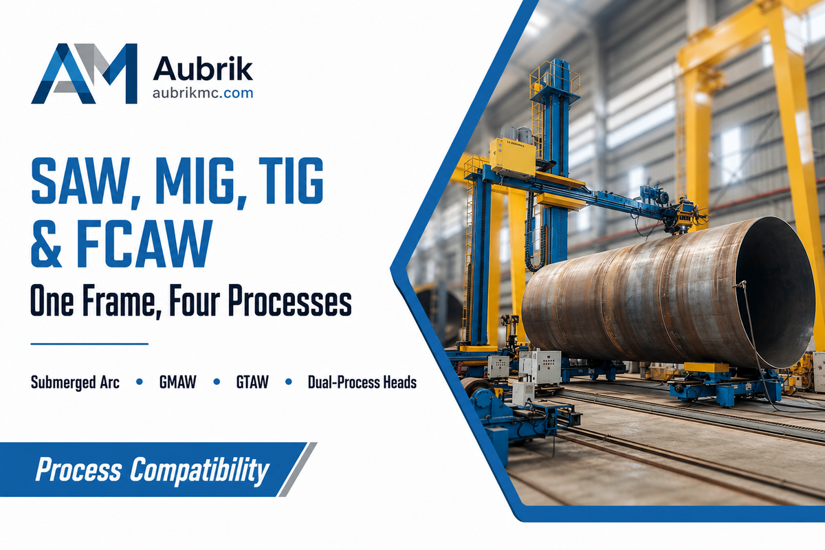
The majority of column and boom welding systems employ sub-arc (SAW), MIG welding (GMAW), TIG/GTAW, and flux-cored (FCAW) welding on a single boom, typically paired with a welding power source appropriate to the specific job and available at the shop. As an illustration of true dual-process capabilities, Koike’s Cricket-II manipulator, capable of SAW, GTAW, and GMAW, is rated for a maximum of 500 lb, and AMET individually configures dual-head arrangements – TIG + Plasma, TIG + MIG, and SAW + GMAW-as seen in a dual-headed MIG and SAW column and boom manipulator manufactured for LJ Welding and currently installed in a client facility. The verification of this two-manufacturer approach is critical, as it refutes the common mistake buyers make in believing a single manipulator locks the shop into one welding process for the machine’s service life.
SAW carries the group’s own productivity limit: an article from a Miller Electric welding engineer states the maximum deposition rate for single wire SAW to be around 40 lbs/hr and for double wire SAW it’s in excess of 100 lbs/hr, on metal between 3/16 and 5 inch thick at currents from 350A (thinner parts) up to more than 1,000A (thick parts), often at 100% duty cycle. MIG/GMAW can give up some of that ceiling but with a quicker set up and no flux recovery systems to maintain. TIG/GTAW can sacrifice its speed to achieve excellent root pass and cladding quality on corrosive work, delivering the most uniform welds and the steadiest weld performance of the three when quality welds matter more than speed. Aubrik’s pipe welding manipulator (FWM series) exemplifies how one machine frame has been constructed for pipe welding automation using a combined SAW and GMAW welding head.
Manipulator, Positioner, or Robot: The 3-Way Motion Split
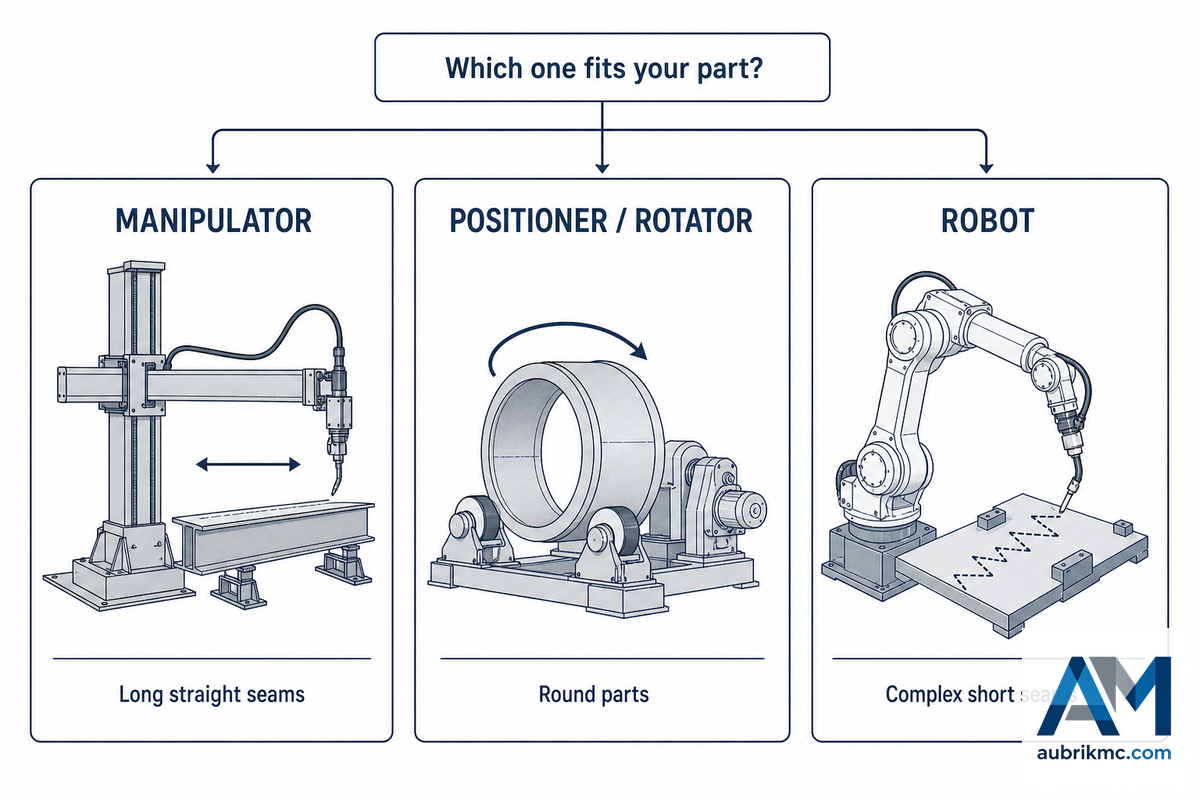
To select the best machine for a particular job three things need to be considered: what length is the seam, how large is the workpiece, and whether the geometry repeats from job to job. If you answer those three, then usually two out of three machine categories will be immediately discarded. A common mistake buyers make here is defaulting to whichever equipment class their shop already owns, rather than checking the seam and part profile against the table below first.
| Criterion | Column & Boom Manipulator | Positioner / Rotator | 6-Axis Robot |
|---|---|---|---|
| What actually moves | Torch travels; part usually fixed | Part rotates/tilts; torch fixed | Torch follows a taught 3D path |
| Best-fit seam | Long, straight or gently curved | Circumferential, on round parts | Short, complex, multi-angle |
| Typical part size | Large: tanks, vessels, wind-tower cans | Cylindrical, scales with capacity | Small-to-medium brackets, weldments |
| Programming effort | Minutes — set speed and angle | Minutes — set rotation speed | Hours — per-part teaching |
| Relative capital cost | Mid | Low-to-mid | Highest |
| Process fit | SAW/MIG/TIG/FCAW, high deposition | Same processes, part-side | Mostly GMAW, high part-mix |
| Repeat volume needed to justify it | Low — pays off on long seams even at low volume | Low-to-medium | High — teaching cost amortizes only with volume |
| Limitations / not suitable for | Complex multi-angle access without an added trolley/boom combo | Seams longer than the table or roller reach | Long, low-mix, single-geometry seam work — teaching cost rarely pays back |
Real world use of the three types of machines shows that they aren’t always either/or, but often the manipulator is accompanied by either a positioner or a rotator so that the torch stays static while the part rotates around it – this is what this family of machines was created to do. On real production lines running a mix of fabrication projects, the cost-effectiveness case usually comes down to repeatability and throughput: where the seam appears often enough, a manipulator’s increased productivity justifies the setup time and investment. Aubrik has produced a rotator vs. positioner selector tool which goes through the same three question approach as applied to the part rotation portion of the equipment combination.
Arc-On-Time Economics: the Real Operator-Factor Numbers
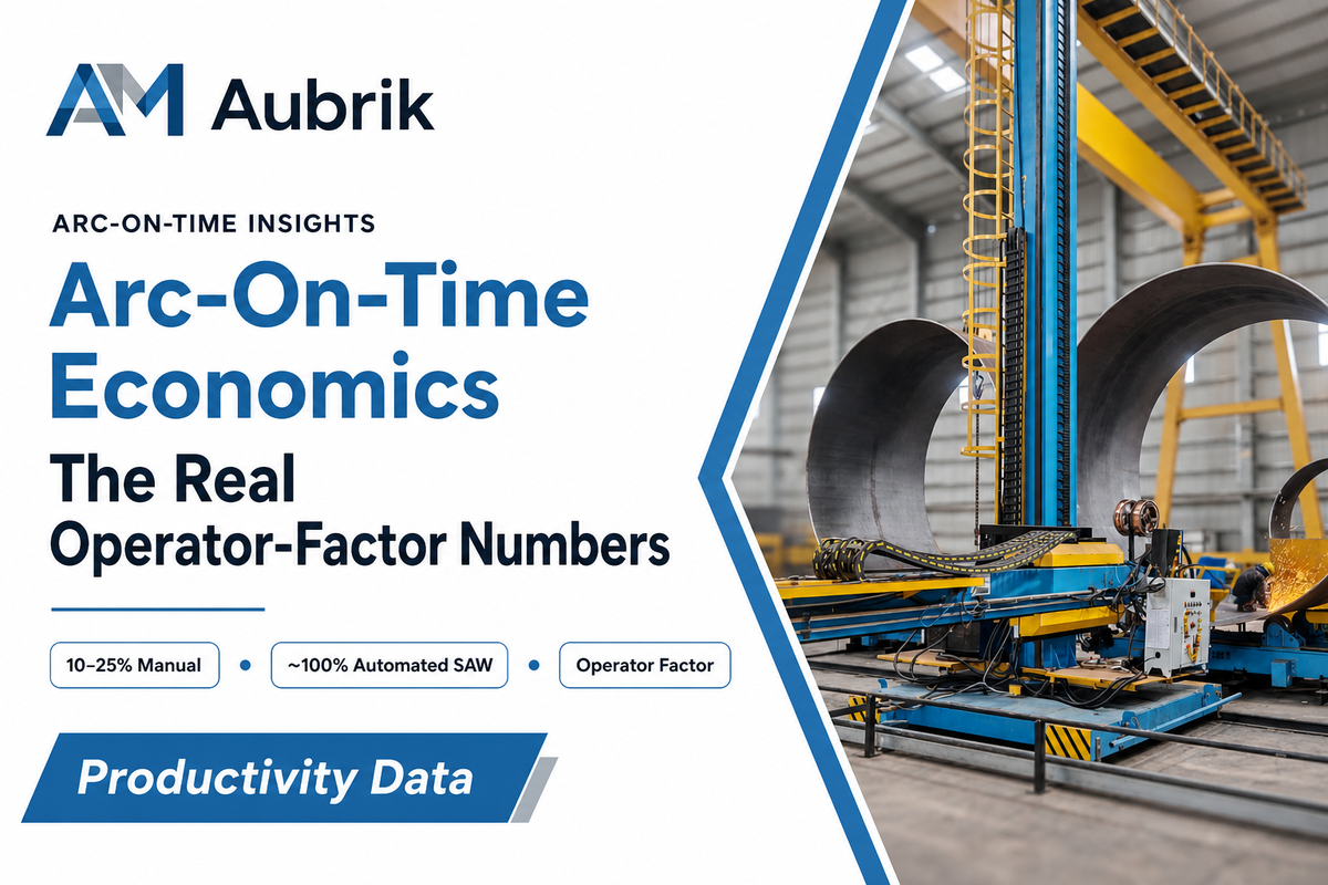
“Operator factor” — the ratio of arc-on time to total shift time — determines manual welding productivity more accurately than most buyers of this equipment realize. Miller Welds, for example, suggests the average semi-automatic welding operator has only a 10-12% operating factor, while one plant manager, utilizing cloud arc-monitoring on about 4,000 lbs of solid wire daily, feels that 25% is considered “solid” and 40% to be a remarkable high performance limit. In the May issue of The Welder, a publication of the Practical Welding Today magazine, the ESAB staff stated the average industry operating factor to be around 20%, which equates to 12 minutes of arc-on time per hour. “The only welding process that readily approaches 100% arc-on time, and will probably get there as more applications are fully automated, is SAW”. According to Airgas, a firm that has compiled the data from over 2,000 shops, the operating factor is now decreasing and is currently around 10-12% – five years ago it was approximately 15%.
“Five years ago, the operator factor for most shops was about 15%, but the more studies we do now, we’re seeing it creep down to 12% to 10%.”
That convergence point-approximately 10-25% for manual, creeping toward 100% only at fully automated welding, even for SAW-is a safer number to build a plan around than a single manual vs. automated data point, inasmuch as it’s based on four disparate, published sources, not on vendor marketing data. That economic logic remains the driving factor, and at 15% operator time, the welder still occupies just 9 minutes of each 60-minute hour welding joints; any gain in efficiency on a long, repetitive seam-without adding downtime, rework, or extra labor costs-will, over time, more than pay for a manipulator. One real-world, named example helps quantify the benefits: Custom Steel Fabricators Inc. (Columbia, TN) recently replaced a manual turning-roll and manipulator arrangement with a Pemamek column and boom system for a 156” dia x 0.5” thick 2205 duplex stainless alloy shell, president Tony Sciotto simply states, “By using the side-support arms we’re now able to support the cylinder as we fit the joint and also throughout the welding process. No more manual fit ups.”
Setup, Seam Tracking & Common Torch-Positioning Problems
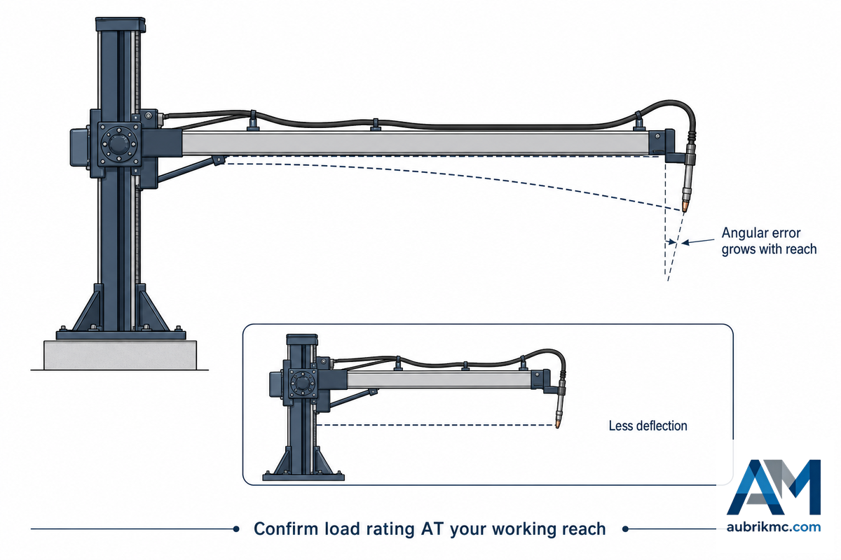
More often than not, torch positioning errors on a C/B manipulator aren’t due to a malfunctioning controller, but rather the boom itself — most pronounced on longitudinal welds and along longer lengths of pipe where a tiny angular discrepancy grows to become a significant issue as it travels further, disrupting the whole shop’s workflow for the remainder of that shift. On the online mechanical forum eng-tips.com, one mechanical engineer demonstrates the dynamics of a truly out-of-balance, 400-kg boom load: “you need to figure out the center of gravity of your boom and apply that information to your structure…what happens when you turn the boom through a few degrees and the loading is now bending your ‘vertical’ members?” — a cantilever action that manifests as boom drift just when you can’t afford for it to: i.e., the furthest point of reach, and least observed position.
Engineering Note: A column and boom manipulator will exhibit more, not less, deflection on its boom at maximum reach than when it’s retracted–so confirm its capacity at the *working* reach required, not the maximum listed figure. And keep the column and boom welding manipulator manual for your specific model handy when setting up, since it lists torque and cross-slide backlash specifications that differ enough between vendors to make a generic checklist unreliable.
In the field, the best method typically falls into a two-step pattern — and you can understand why designers continue to rework the system for optimal efficiency: first, give the operator the ability to quickly and easily position the torch close to its weld path in an unpowered state, then switch to an accurately controlled drive for the welding operation itself. Allowing an unpowered process just for the final torch positioning stage is often what wastes most of the manual effort. Aubrik’s own welding positioner load capacity calculator follows a similar real-world philosophy on the part-rotation end of a cell.
Standards That Govern Weld Quality on a Manipulator Cell
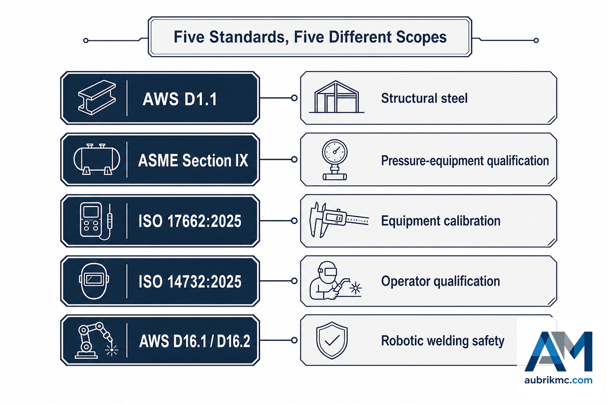
Whether your shop calls it a welding column and boom or a manipulator, there’s no single product certification for it – the machine itself typically carries CE marking for electrical and mechanical safety, while weld quality and cell safety are governed by a set of standards with genuinely different, non-overlapping scopes. Treating them as one undifferentiated “compliance stack” is itself a common mistake: AWS D1.1 is specifically the structural welding code for steel, not a general manipulator-cell authority, and it doesn’t cover the robot/automation safety questions a mechanized cell actually raises.
| Standard | What it actually governs |
|---|---|
| AWS D1.1 | Structural steel welding procedure and welder/operator qualification — scoped to structural steel, not a general-purpose authority |
| ASME Section IX | Welding procedure and performance qualification within pressure-equipment code contexts |
| ISO 17662:2025 | Calibration, verification and validation of already-installed welding process-control equipment — not a design or manufacture standard |
| ISO 14732:2025 | Qualification testing of the welding operator/weld setter running mechanized and automatic welding equipment |
| AWS D16.1 / D16.2 | Safety requirements for the design, manufacture, and operation of arc-welding robot systems and ancillary equipment, and a guide to the components of robotic/automatic welding installations |
Among these, the newest – ISO 17662:2025, published 2025-09-09, superseding the withdrawn 2016 edition – is worth reading precisely rather than by headline: its actual clause-level changes in this revision are limited to the stud-welding clause, adding soldering to the brazing clause, and a bibliography update – the arc-welding clause most relevant to SAW/MIG/TIG/FCAW manipulator calibration was not revised this cycle. It governs verifying equipment already in service, so a shop auditing itself against ISO 3834 needs travel-speed control that can actually be calibrated and documented against it – which is the practical argument for closed-loop, encoder-fed drives over open-loop VFD control, not a claim that the standard mandates any particular drive technology.
Integrating a Manipulator With a Positioner or Rotator
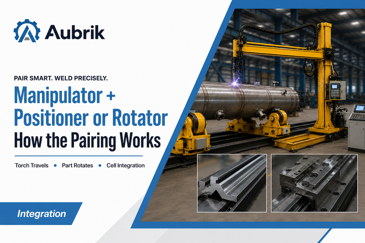
On cylindrical work, the standard cell pairing is a manipulator holding the torch stationary in travel while a positioner or rotator turns the part – and the scale mismatch between the two machines is worth planning for explicitly. AMET’s own product line illustrates it: its column and boom manipulators carry 150-600 kg at the boom end, while the turning rolls, turntables, and positioners it sells alongside them run from 2.5 to 150 tons. In that pairing, the manipulator is never the constraint on total part size – the rotating equipment is.
Koike’s pipe-welding package makes the same point from the product side: a Cricket-II manipulator paired with turning rolls and a flux hopper, sold as one system rather than two separate purchases – the same layout logic behind Aubrik’s own pipe rotator line pairing with a boom-mounted torch for long pipe spools.
Guarding and access, not motion, is the integration question that gets skipped most often.
As the moving axes, payload, and reach scale up – particularly once a manipulator is combined with a rotator underneath it – the guarding, restricted-space, and ventilation requirements around the cell scale with it; OSHA’s general machine-guarding rule (29 CFR 1910.212) applies to any powered rotating or traveling equipment on the floor, manipulator included, and higher sustained deposition rates from full automation raise the same fume-extraction question a shop would already be asking about its welding bays generally.
What’s Changing: Closed-Loop Motion Control and ISO 17662:2025
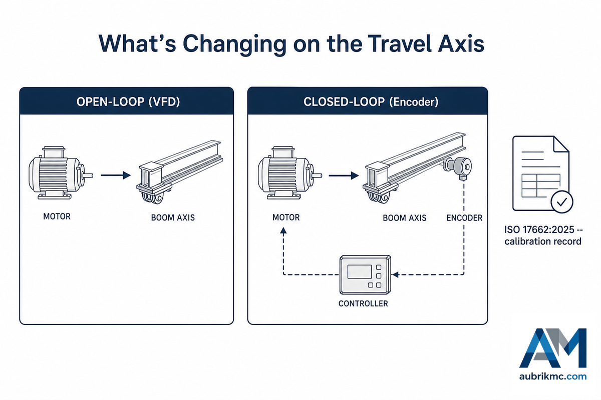
Documentation requirements, not just speed, are driving the current shift toward closed-loop manipulator control.
ISO 17662:2025’s calibration/verification requirement for process-control equipment gives shops running ISO 3834 quality systems a real reason to specify encoder-fed travel-speed control now rather than retrofit it later.
AMET sells that retro directly — a servo motor and encoder retrofit which converts any manual or open-loop boom axis to a unit with “precise programmable control,” that it labels as a boom performance upgrade rather than a full-machine replacement, meant to minimize boom idle time between passes when welding large pressure vessels and pipe sections. A further patent application granted within the same window, EP4347177B1, in the same period, suggests that manufacturers are also actively re-engineering the boom positioning system itself, rather than just its controls.
For a buyer contemplating a purchase in 2026, the pragmatic action is this: with even the remotest possibility of an ISO 3834 audit sometime in the machine’s lifetime, order travel-axis encoder feedback now, even if the current job doesn’t technically require it; late retrofit will always be more expensive, and the calibration evidence ISO 17662:2025 demands will always be more easily sourced from a closed-loop than from an open-loop axis. Broad market-size estimates for welding automation are readily available in many industry reports but will be used here merely as a point of reference and not the primary driver for this guidance, as reports differ significantly by source.
When Not to Buy a Column and Boom Manipulator
If the seam is too short, if the part geometry varies greatly job-to-job, or if the volume is insufficient to amortize even a few minutes of setup, then let the per-part teaching cost of a 6-axis robot (or the costs of manually welding) be the competitive factors; these will prove to be less costly overall than the purchase of a boom manipulator for those tasks.
This rationale also holds in reverse: the machine isn’t the right choice when rotation, not travel, is the bottleneck.
A manufacturer whose difficulty lies in welding round parts’ circumferential seams will be best served by first purchasing an appropriately sized positioner or rotator, onto which a boom manipulator can then be mounted. As discussed under “Sizing,” it’s rarely a wise decision to purchase the largest available manipulator frame “just in case”; capacity beyond your actual requirements adds costs through increased idle time without providing additional utility.
Key Takeaway
Size a boom welding manipulator to the full load carried by the boom and gun assembly at their full working extension, rather than at the maximum listed torch load (which often appears on a headline rating that implies an extreme but less common scenario). Make sure to check if AWS D1.1 for structural steel applies to your work, since it’s not an all-encompassing authority. Again, if there’s a reasonable probability of an ISO 3834 audit during the machine’s service life, specify encoder feedback now.
Reviewed by the Wuxi ABK Machinery (Aubrik) Technical Team
Since 1999, Aubrik has supplied a wide variety of welding and cutting automation solutions, including boom welding manipulators, positioners, and turning rolls. The guidelines on manipulator sizing and scope-of-work as discussed herein are derived from the methodology employed by our engineering team when specifying and configuring manipulator cells for customers transitioning from manual to automated welding.
We supplement this information by referencing independent trade-press articles, relevant standards, and patent filings, as we don’t rely on information from a single source.
Frequently Asked Questions
Q: What is a column and boom welding manipulator and how does it work?
A column and boom welding manipulator is a machine with a vertical column and a horizontal boom that carries the welding torch and moves it along a joint at a set travel speed, instead of the operator holding and walking the torch.
The column sets working height, the boom sets horizontal reach, and a motorized trolley can index the whole assembly along a rail for repeat seams. Underneath, the workpiece itself usually stays still or turns on a paired positioner or rotator. Four subsystems do the real work: column, boom, an optional trolley for indexing between seams, and a control system that sets and holds travel speed — get any one of the four wrong and the symptom shows up as a drifting torch or an inconsistent bead, not as a line item on the spec sheet buyers usually compare first.
Q: What is the difference between a welding manipulator and a welding positioner?
A welding manipulator moves the torch; a welding positioner moves the workpiece instead, clamping it to a tilting or rotating table under a torch that stays in one place.
Most heavy fabrication shops end up owning both: the manipulator holds and travels the head along long seams, while the positioner turns or tilts the part so the joint sits in the flat, downhand position. Neither machine substitutes for the other — a manipulator cannot rotate a round tank shell, and a positioner cannot travel the length of a long pipe spool or wind-tower can, which is why the two are so often specified as a matched pair rather than an either/or choice.
Q: What size manipulator do I need for my workpiece?
Start from the longest seam or largest radius you need to reach, then size the boom-end load for the full mounted stack — torch, wire feeder, flux-recovery unit, camera, and cross-slide — not the torch alone.
A submerged-arc package can weigh close to double a bare MIG torch. Buying one size larger than that real number just adds idle travel time and cost, not usable capacity — confirm the load rating point (working end vs. opposite end) with the supplier before ordering. Vendor spec sheets published for this guide cluster boom-end load into roughly four duty tiers, from about 7 kg on the smallest portable frames up past 600 kg on heavy-duty models, so matching your real stack to the right tier matters more than chasing the biggest number on the page.
Q: What welding processes can a column and boom manipulator run?
Most frames run submerged arc (SAW), MIG/MAG, TIG, and flux-cored (FCAW) on the same boom, single or tandem wire, and dual-process heads are a genuine, commercially available option, not just a marketing claim.
SAW suits thick structural and pressure-vessel work where deposition rate and arc-on time matter most; MIG handles faster medium-plate jobs without flux handling; TIG and cladding cover root passes and corrosion-resistant overlay where bead quality is critical.
Q: How is a column and boom manipulator different from a 6-axis robot?
A 6-axis robotic arm teaches a complex 3D path point by point, suited to small parts with many short, irregular seams; a column and boom manipulator is purpose-built for long, repetitive, mostly straight or circular seams where the travel path barely changes from part to part.
For that narrower job, a manipulator typically delivers a higher deposition rate per dollar of capital than a robot covering the same working envelope, because it needs far less programming and no per-part teaching — a robot’s teaching cost only amortizes once part volume is high enough, which is exactly backwards from how a manipulator pays off: it earns its keep on a single long seam, at low volume, the first time it runs.
Q: What is the boom-end load capacity, and why does it matter?
Boom-end load capacity is how much weight the boom can carry at full extension without losing torch positioning accuracy, and it matters because under-rating it is the single most common sizing mistake buyers make.
It has to cover the whole mounted stack, not just the torch, or the boom deflects and welds drift off the joint — and some vendors’ published capacity only applies at a specific mounting point, not uniformly along the boom.
References & Sources
- ISO 17662:2025, Welding, calibration, verification and validation of equipment — International Organization for Standardization
- ISO 14732:2025, Qualification testing of welding operators and weld setters — International Organization for Standardization
- AWS D1.1 Structural Welding Code, Steel — American Welding Society
- AWS D16 Committee on Robotic and Automatic Welding (D16.1 / D16.2) — American Welding Society
- 29 CFR 1910.212, General Requirements for All Machines — Occupational Safety and Health Administration
- Maximizing Arc-On Time — The Fabricator / The Welder
- Improving Deposition Rates With Submerged Arc Welding — The Fabricator / The Welder
- What Is Welding Arc-On Time and Are You Overestimating It? — Miller Electric
- EP4347177B1, Welding boom — European Patent Office / Google Patents
Related Articles
- Welding Rotators & Turning Rolls, 2026 Engineering Guide — the rotating half of most manipulator cell pairings
- Welding Positioners & Turntables Selection Guide — choosing the part-side equipment a manipulator pairs with
- How to Use a Welding Positioner — operating the paired equipment day to day
- Aubrik Column & Boom Welding Manipulators — model range, sizing tools, and quote request
- Pipe Welding Manipulator (FWM Series) — SAW/GMAW dual-process manipulators for 50–3,000mm pipe