Get in Touch with Aubrik Company

Wind Tower Girth Welder
Wind Tower Girth Welder — Automatic SAW System for ⌀3–8 m Tower Sections
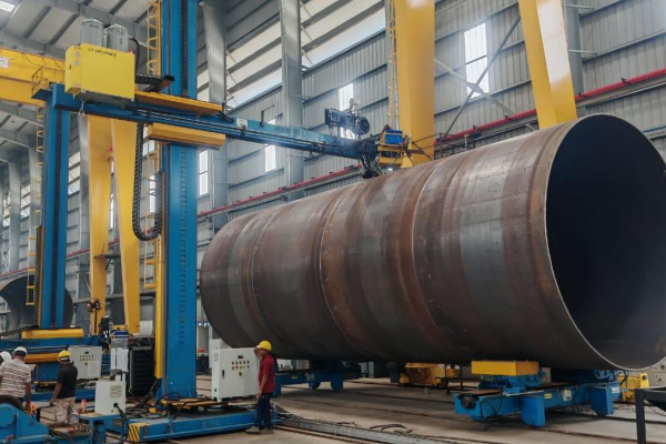
Automated wind tower circumferential welder used to produce the circumferential seam welds that hold 70-90m towers together. Aubrik produces consistent, NDT-welder grade welds on S355 sections – with laser seam tracking and 80% flux recovery designed-in.
✔ ISO 9001 & CE certified
✔ Est.1999 (Wuxi ABK / Aubrik)
✔ 1,000 welding sets / year capacity
✔ Up to 99.8% NDT pass rate in the field
⌀3.0–8.0 m
Tower diameter range
6.5–80 mm
Wall thickness
SAW
Submerged arc, DC1000/1200
±0.01 mm
Laser seam tracking
80%
Flux recovery rate
2 → 5 / day
Sections welded (field result)
[SYS-DIAGNOSIS]
Why manual girth welds put wind towers at risk
A wind tower girth welder is the automatic machine that fuses rolled steel “cans” into a completed tower section with a circumferential submerged arc weld. On a 70-90m tower, those circumferential joinings withstand wind load, thermal cycles, and – offshore – salt spray and fatigue. A single defected pass becomes a structural liability for the life of the turbine.
What manual girth welding costs you
SEC.01
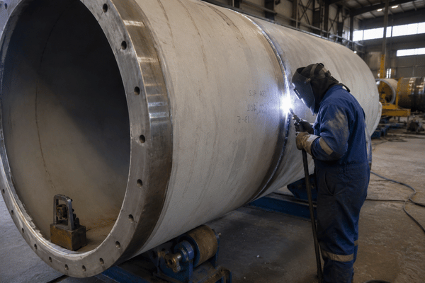
[DEFECT_RATE]
Manual circumferential welds with defect rates approaching 10% depend on operator skill, hour after hour, on a rotating structure.
SEC.02
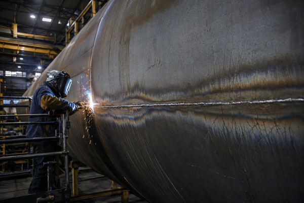
[STRUCT_STRESS]
A continuous metallurgical notch – the girth weld and its heat-affected zone sit under flexural stress, where cracks initiate and grow over time.
SEC.03
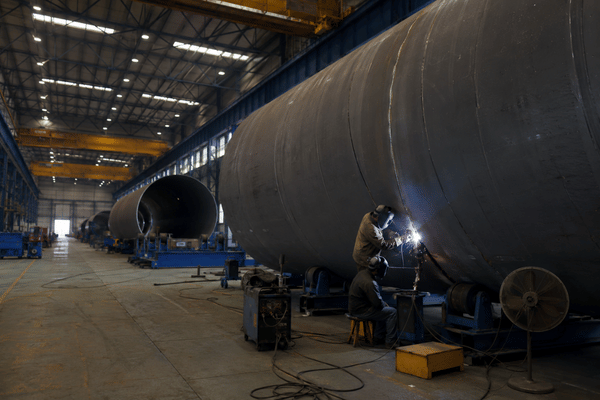
[PROD_LIMIT]
Limited throughput – manual arc-on time is only 20-30% of the shift, limiting how many sections a line can ship.
[Aubrik _ENGINEERING]
Aubrik engineers their girth welder specifically around this very failure mode. The reason manual girth welds miss is structural – consistent weld quality depends on consistent rotation and a head that won’t drift. So we use a stable AC frequency-conversion system to turn the tower at a steady speed, because seam tracking that holds the head to 0.01mm only works when the part in hand moves in a predictably regular way. Aubrik provides a defect-free circumferential girth weld with minimal human interaction, even on thick S355 sections preheated to 120 C and welded in ambient conditions down to 20 C.
[IMPACT_SCALE]
As wind power expands to fully realize its potential, every tower section that ships defect-free is another hurdle removed from the renewable power supply chain. Consistent wind tower circumferential welding – not heroic rework – is what keeps that pipeline flowing, and it is precisely what a dedicated Aubrik circumferential weld prep is built for.
[SYS-01] Automated Girth Welder
Aubrik Wind Tower Girth Welders WT-GW-I & WT-GW-II
Two models cover the entire onshore & offshore wind tower work scope. Both are built with industrial-precision parts selected for long service life in abusive fabrication settings – Lincoln Electric SAW power, Siemens frequency-conversion speed control, and SEW motor reducers.
Each is an automated girth welder (AGW): a mobile welding head that unilaterally controls seam tracking, bringing fully automated circumferential tower welds to a previously manual process. It is that transition that turns weld quality from an operator variable into a high-quality, repeatable result – and allows a line to ramp up productivity without adding skilled headcount.
We build two machines, not one, because a 40mm onshore wall and 80mm offshore wall will require different rotation torque and heat input – to run either job on a single frame can lead to 10% more slow, sloppy welds. That’s why the WT-GW-I and the WT-GW-II cover the waterfront. whether an EU buyer running 50ton onshore cans or a US buyer welding 120ton offshore sections will buy a frame on which the heaviest of their sections fits. After all, a configurable automatic girth welding machine built around your tower will always beat an off-the-shelf average.
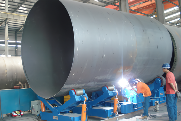
Girth Welder Models
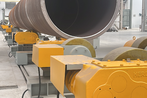
WT-GW-I
Onshore & mid-size towers
This is the machine designed for 3.0-4.5m sections in the 6.5-60mm thickness range. Hebei manufacturers use the WT-GW-I to produce 6 sets of 3.8m / 40mm onshore towers daily.
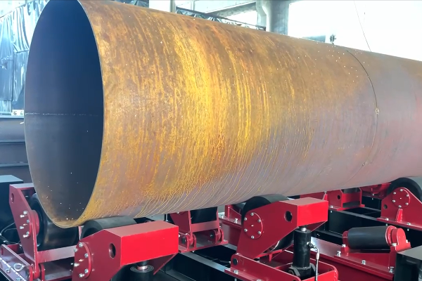
WT-GW-II
Large offshore & heavy-wall towers
This model handles the 4.5-8.0m range in the 8.0-80mm section thickness range. Fujian offshore project use a WT-GW-II on 7.5m / 70mm towers, delivering output similar to four man-welding equivalent rates.
[SPEC-02]
Specification Parameter Matrix
| Specification | WT-GW-I | WT-GW-II |
|---|---|---|
| Applicable tower diameter | ⌀3.0–4.5 m | ⌀4.5–8.0 m |
| Applicable wall thickness | 6.5–60 mm | 8.0–80 mm |
| Welding method | Submerged Arc Welding (SAW) | Submerged Arc Welding (SAW) |
| Welding power supply | DC1000 + NA-3 | DC1200 + NA-3 |
| Wire diameter | ⌀2.5–6.0 mm | ⌀3.2–6.0 mm |
| Welding speed | 0.3–2.5 m/min | 0.2–2.0 m/min |
| Rotation speed | 0.1–1.0 r/min | 0.05–0.8 r/min |
| Power supply | 380V / 50Hz, 3-phase | 380V / 50Hz, 3-phase |
| Overall dimensions (L×W×H) | 4500×1800×2200 mm | 5200×2000×2500 mm |
| Net weight | 3,800 kg | 5,200 kg |
| Applicable steel grades | Carbon / low-alloy / S355N/NL | Carbon / low-alloy / S355K2/NL |
[DATA-03]
The ⌀3–8 m Fit Window
The configuration built around your largest section, heaviest wall and your most ambitious output target can be found here in this single view. Highlighted row is for which component the machine is designed.
| If your towers are… | Diameter | Wall | Steel grade | Recommended model |
|---|---|---|---|---|
| Onshore, standard | ⌀3.0–4.5 m | 6.5–60 mm | S355N/NL | WT-GW-I |
| Mixed onshore/offshore | ⌀4.5–6.0 m | up to 70 mm | S355NL | WT-GW-I or II* |
| Offshore, heavy-wall | ⌀6.0–8.0 m | up to 80 mm | S355K2/NL | WT-GW-II |
| Non-standard / repair | custom | custom | custom | OEM build |
*Borderline diameter – we configure rotational and boom strength to best suite your largest sections. The automatic girth welder can be easily interfaced to column-and-boom welding manipulators, welding rotators, turning rolls, positioning machinery and CNC cutting machines from Aubrik ‘s extensive line, ensuring efficient integration with your existing material flow.
Automatic vs Manual Girth Welding – The Manual-Weld Penalty
Automation is more than a slogan – it’s a financial case backed by six tangible spreadsheet metrics comparing a proficient human crew to the AGW when working on the same structure component.
Look at the table as a throughput story, not a quality one. It is increased arc-on-time from one-quarter of a shift to three-quarters of a shift that leads to two-sections-a-day to five-sections-a-day – the key factor in on-schedule delivery. The flux and defects lines protect that hard-won capacity by eliminating waste.
It also factors in downtime. Traditional girth welding suffers from loss of time to reset position, strike the arc, correct uneven progress and even to move section to section, an unseen cause of lost capacity and added expense. As the Aubrik system continues to run without interruption after load once a tower section has been secured within, the causes for such interruptions such as operator fatigue or positional variation are eliminated by structure design. A saving of 20% of the working shift on heavy structures at both onshore and offshore manufacturing sites provides margin.
// Data MatrixAGW Comparison
Metric
Manual girth welding
Aubrik automatic
Circumferential weld defect rate
~ 10-12%
down to 0.2-0.3%
Arc-on time (shift utilisation)
20-30%
80%+
Tower sections per day
2
5
Off-centre / misalignment defects
up to 8%
0.2% (+/- 0.01 mm tracking)
Unused flux wasted
~ 25%
~ 5% (80% recovered)
Typical field NDT pass rate
~ 95% industry avg
up to 99.8%
[SYS.DOC] // WORKFLOW SPECIFICATION
The 4-stage defect-zero girth welding workflow
This is perhaps the most important thing; people always say “if it’s automatic then it has zero defect welds.” But no – even thick S355 offshore structures will suffer from cold cracks and hydrogen when they are put together too fast without any consideration for inter-pass conditions or heating or the time required to cool enough to inspect.
Let’s be frank, on its own, automation is not industry truth. In fact, it’s actually the hard trade-off between raw speed versus the discipline of controlling metallurgy, and Aubrik offers the solution to that compromise through smart process control under that automation – with no sacrifices on either side. That process control gets engineered into four stages – the exact four that Aubrik applies across the EU and US for its industrial clients on 120-ton offshore S355 sections heated to 120C.
[EXPERT.LOG] // METALLURGY CONTROL
“With heavy-wall S355, the machine is half of the picture,” explains Lead Structural Engineer Jian Li. “We size the rotation speed to each section to control cooling out of the cold cracking window, then we align it precisely with seam tracking-to hundredths of a millimeter.”
FIELD DEPLOYMENT
Proven Field Results — Offshore & Onshore Wind Projects
Aubrik Tower-Build Scenarios
Each recommended Aubrik setup matches one of the four scenarios shown here, and-in each case-we reference a real project to prove the point, not a “brochure” claim. In the case of a purchasing professional evaluating a new welding vendor, risk often involves unverified claims, or a trust deficit. That’s why every value reported by Aubrik corresponds to an actual 50-120 ton offshore tower fabrication, welded to a specified 120°C preheat, with a confirmed NDT pass rate.
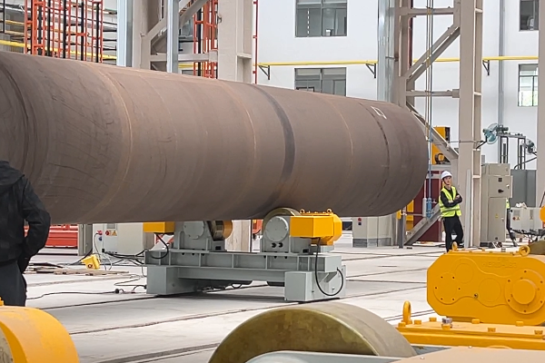
SYS-ID
Tower-Build Scenario
Setup
Named Result
[OP-01]
Onshore mass production
WT-GW-I, single-head SAW
Henan plant: 500 → 1,200 sections/yr, 99.7% NDT
[OP-02]
Offshore heavy-wall
WT-GW-II, controlled preheat
Guangdong Qingzhou III: 80 sections, 2 yrs undamaged, +35% efficiency
[OP-03]
On-site repair / reinforcement
Portable girth welder
Jilin Longzhao: 119 turbine bases reinforced, all passed NDT
[OP-04]
Related heavy fabrication
WT-GW-II, SAW
Jiangsu petrochemical: ⌀5.8 m tanks, 3× efficiency, 100% NDT
DATA // 01 120 sections zero NDT defects on ⌀6.2 m / 75 mm S355NL Jiangsu offshore wind farm — 30% shorter manufacturing cycle vs manual
DATA // 02 78% less flux waste, output 2 → 5 sections/day Shandong manufacturer, WT-GW-I — lower cost, faster delivery
DATA // 03 8% → 0.2% off-centre defects, 90% less correction time Jiangsu manufacturer — laser seam tracking ±0.01 mm
DATA // 04 180,000 RMB flux cost saved by one manufacturer (/yr) Through 80% flux recovery — alongside a jump from 2 to 5 tower sections per day.
Certifications & Compliance
Aubrik ships against european standards and our documentation will pass your toughest supplier audit – without exception. Skipping those procedures creates risk-because even a seemingly well-built machine may fail the audit in your own facilities. Each Aubrik girth welder to CE, ISO 9001, and ISO 15614-1 standards to enable US or European buyers to sign off for welding approval for a 120-ton offshore module without issue, including supporting documentation like certified WPQR to reflect our 120C preheat temperature for every S355 weld procedure.
01
ISO 9001
Quality management system02
CE
European conformity03
ISO 15614-1
Weld procedure (WPQR)04
S355 N/NL/K2
EN 10025 steel grades05
NDT: UT + MT
Post-weld inspectionEngineer’s note — offshore NDT timing
For thick-wall S355 offshore joints, codes require a post-welding waiting time before NDT (up to 48 hours) so that any Delayed Hydrogen-Assisted Cracking (DHAC) has a chance to reveal itself prior to acceptance. Our standard WPQR and inspection protocol includes this wait time, so a pass is a passing pass.
Procurement Guide — Lead Time, Warranty, OEM & After-Sales
The biggest risk in sourcing welding equipment from China isn’t the machine itself, but what happens in the 2+ years after you buy it. Around 30% of buyers report a gap in post-purchase support, with hidden costs in maintenance, spare parts, and shipping delays quietly swallowing any price savings.
The reason a EU or US buyer hesitates isn’t emotional, but structurally fundamental – a 120-ton offshore tower or even a 50-ton onshore one can’t wait three weeks for a key spare part. Aubrik provides the service structure to prevent these painful surprises.
What you get with an Aubrik girth welder
- 1-year free warranty on every machine.
- 24/7 live technical support with 4-hour response time: a single Guangdong-based project achieved an on-site, 24-hour fix and a 98% customer satisfaction rate on an emergency issue.
- OEM custom builds: One custom 7.8 m / 75 mm S355K2 offshore construction for a Fujian offshore platform has been running successfully for 2 years with a 99.9% NDT pass rate.
- On-site installation, commissioning, operator training, genuine OEM spare parts, and software updates.
[DATA-MATRIX]
Pricing & lead-time factors
Price and delivery lead time correlate directly to the specifications you require – not a generic estimate based on some typical configuration. We work with your parameters to build a custom quote. These key cost drivers are transparent.
Model & rotation sizing Largest diameter and heaviest wall thickness you weld
SAW power config DC1000 vs DC1200, single vs multi-pass duty
OEM scope Custom frames, integration with existing rotators/manipulators
Certification level WPQR scope, inspection package for your market
Wind Tower Girth Welder Engineering & ROI Evaluation Tools
model selector
Configure your optimal girth welding system based on specific shell diameters, plate thicknesses, and production line layout requirements.
Launch Selector
throughput roi calculator
Evaluate investment payback periods and calculate measurable duty-cycle capacity improvements driven by automated multi-arc welding integration.
Calculate ROI
flux savings calculator
Estimate cost reductions in welding consumables by simulating material recovery efficiency and precision flux distribution control.
Analyze Savings
Build towers that clear NDT the first time
Give us the inside-diameter, wall-thickness and ideal output rate for your tower: Aubrik engineers will present the optimum welding system and will then build the precise, itemised quotation covering every component for that particular setup along with detailed lead-times at each stage.
Frequently Asked Questions
01 What is the benefit of an automatic wind tower girth welder over manual welding?
Get a 99%+ NDT pass rate, and achieve 300-500% production increase over manual welding. Consistency is the critical component: Manual girth welding typically shows an 8-10% defect rate because the weld quality is inherently dependent on the welder’s performance while standing on a rotating structure. Aubrik technology’s controlled rotation and laser seam tracking systems minimize these risks and reduce defects to below 0.5%. In one Shandong-based tower fabrication shop producing 50 to 120-ton towers, adopting the Aubrik auto-welder improved weld quality from 12% to 0.3% defect rate, and increased productivity from 2 to 5 towers per day.
02 What tower diameters, wall thicknesses, and steel grades does it handle?
Our equipment set currently supports pipe and tower manufacturing, covering outer diameters of 3.0-8.0 m with wall thicknesses of 6.5-80 mm, specifically designed for welding S355N/NL and S355K2 materials. Customization is available-we recently delivered a custom 7.8 m / 75 mm S355K2 configuration to a Fujian offshore platform that has been operating flawlessly for two years with a 99.9% NDT acceptance rate.
03 How do the laser seam tracking and flux recovery systems work?
Advanced laser vision tracking combined with AI identification creates precise 3D seam data-accurate to within 0.01 mm-and automatically adjusts the welding head for uninterrupted 360-degree welding on any tower diameter. An efficient closed-loop flux recovery system uses vacuum suction and filtration to recapture and recycle up to 80% of excess flux. Clear viewports allow the operator to monitor flux levels without interrupting a welding cycle.
04 Is it suitable for offshore wind towers exposed to salt spray and corrosion?
Yes. The WT-GW-II was built with corrosion-resistant components and precision welding control to withstand the harsh offshore environment and includes hydrogen-cracking considerations when welding S355 material at greater thicknesses by including controlled preheat and NDT timely control. For instance, this girth welder is currently being utilized on an 80-joint project for Guangdong Qingzhou III offshore which, over two years, has experienced no damage. On the same project, our WT-GW-II has seen a 35% efficiency gain over manual welding processes.
05 How do we keep the flux recovery system running smoothly?
Check the vacuum for blockages and the filters weekly, refill the backup flux hopper monthly, and clean it once a year. One Jiangsu customer held a 99.5% operational rate for three years on that routine.
06 What after-sales support and warranty do you offer?
A total life-cycle warranty from day one: onsite installation and operationalization, thorough welder training and ongoing preventative maintenance, 24/7 telephone support (we promise to call back within 4 hours), all guaranteed with original spare parts and software updates under a one-year warranty. When a Guangdong-area project had an issue, an on-site Aubrik representative on-site arrived within 24 hours and a solution was reached in 48. The customer satisfaction was rated at 98% for that issue.