Get in Touch with Aubrik Company

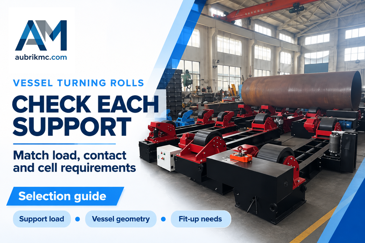
Vessel turning rolls support and rotate a cylindrical vessel on powered and idler rollers so a welder or welding head can work along a controlled seam. Choosing a set starts with the load at each support, the vessel’s contact geometry and the required rotation, not just its total weight.
A pressure vessel with a heavy head at one end can overload a support while remaining below the set capacity. A roll package that fits the diameter can still leave the crane, purge hoses or welding manipulator unable to do their job. This guide turns those questions into a capacity check, a scenario table and vessel details for a quotation.
Vessel Turning Rolls: What the Set Must Do
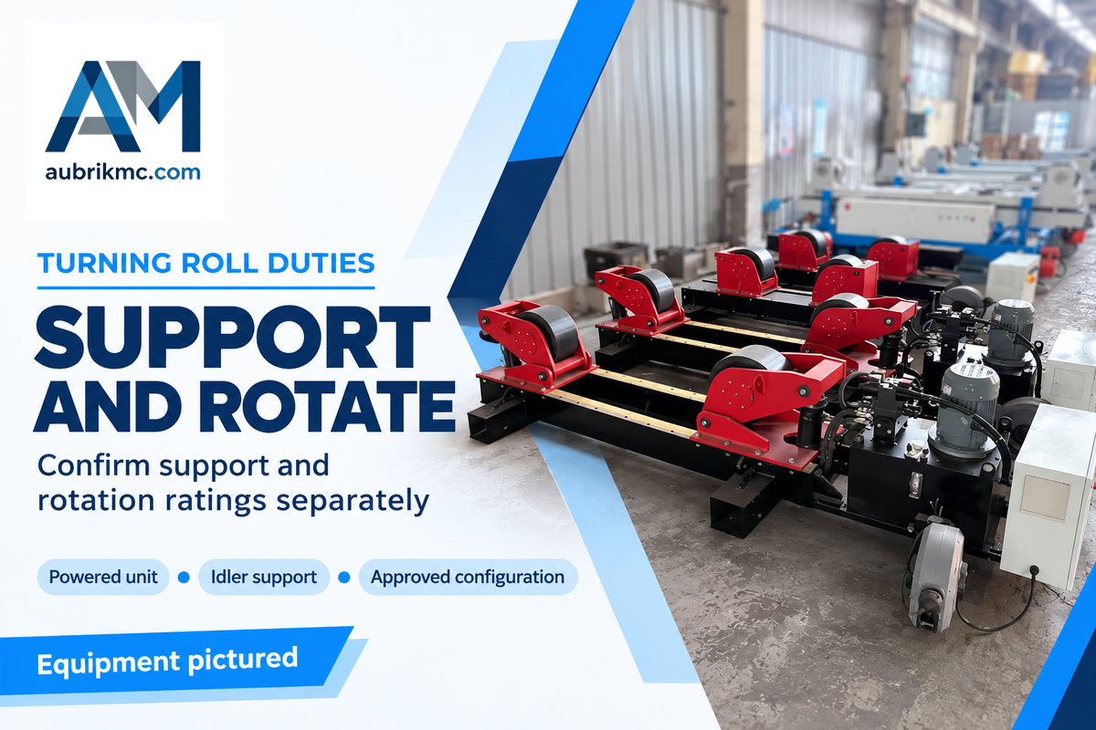
A vessel turning roll set must carry the workpiece, develop traction to rotate it and maintain the weld position, all at the same time. These are independent duties. Begin with the vessel drawing and welding sequence, and ask the supplier to identify support and rotation ratings and allowable operating conditions.
The powered unit transfers motor torque through its wheels; idler rolls support the other contact station without supplying that drive. A pipe or tank may look symmetrical while its heads, internal parts and attached nozzles move the center of gravity. The assembly drawing is more relevant than a bare shell weight estimate.
For heavy-duty pipe welding, specify how the rolls communicate with the welding equipment. Automation requires a defined sequence: which controller commands rotation, which receives a ready signal and what happens when welding work stops. The pipe fabrication team should agree that sequence with the machine integrator.
Koike’s turning-roll sizing guidance distinguishes support capacity from rotation capacity. Its examples describe specific combinations of drive and idler units, rather than a multiplier that applies to every roll machine. Use the same distinction when comparing a heavy-duty package with equipment available for a short rental.
For a general overview of drive arrangements and their operation, refer to the welding rotators and turning rolls guide. The consideration for the vessel here is more specific: is the configuration compatible with the complete fabrication at each stage of assembly?
Turning Roll Capacity: Check Each Support
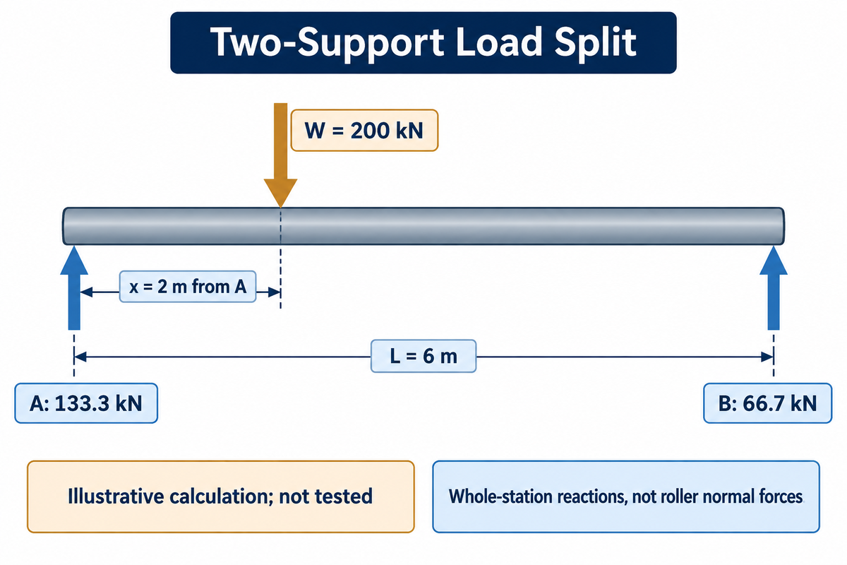
The vessel weight is not necessarily shared equally between the two supports. Their vertical reactions depend on the center of gravity along the vessel and the distance between support stations. Compare each reaction with the corresponding unit’s permitted support load, then check the separate drive and contact limits for that configuration.
Use the Two-Support Load Split before requesting a size
The Two-Support Load Split is a first-order approximation for a rigid vessel resting on two support stations. It’s based on the principles of static equilibrium, as explained in OpenStax examples. Measure the center of gravity from support A toward support B; use one consistent set of units.
Illustrative inputs: total vertical weight W = 200 kN; support spacing L = 6 m; center of gravity x = 2 m from A.
Reaction at B: RB = W × x / L = 66.7 kN.
Reaction at A: RA = W − RB = 133.3 kN.
The reactions add to 200 kN. A carries twice the vertical load of B in this example; choosing two units on an assumed 100 kN per support would miss the heavier end.
These values are calculated, not tested. The results are the vertical reaction of an entire support station, and don’t reflect the normal force on an individual roller. Contact angle, wheel configuration and shell stiffness affect the individual normal forces. Ask the manufacturer to review these against the actual drawing.
The following sensitivity calculation keeps W at 200 kN and L at 6 m and changes only the assumed center of gravity. It shows that for a given total load, changing the location of a heavy subassembly can influence the support rating.
| x from A | R at A | R at B |
|---|---|---|
| 0.6 m | 180 kN | 20 kN |
| 1.2 m | 160 kN | 40 kN |
| 1.8 m | 140 kN | 60 kN |
| 2.4 m | 120 kN | 80 kN |
| 3.0 m | 100 kN | 100 kN |
| 3.6 m | 80 kN | 120 kN |
| 4.2 m | 60 kN | 140 kN |
| 4.8 m | 40 kN | 160 kN |
| 5.4 m | 20 kN | 180 kN |
The calculations separate two different problems. A longitudinal offset of the center of gravity of the entire assembly affects the support reactions. A radial offset from the rotation axis creates a changing gravitational torque as the vessel rotates. Adding an idler can help carry weight, but does not by itself establish that the powered unit has enough traction or starting torque.
For three (or more) support stations, to achieve equal load sharing, justification regarding stiffness, alignment and contact is necessary. Send the proposed support layout back for calculation instead of extending the two-support formula by dividing the weight by the number of units. Always recheck the arrangement when heads, internal assemblies or center of gravity of a given component change.
Vessel Geometry: Diameter, Shell and Contact
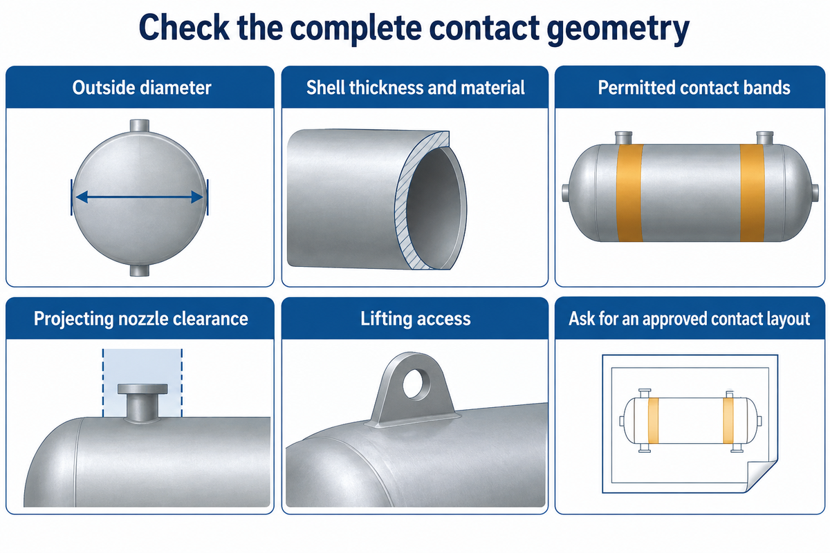
Vessel geometry is more complex than diameter compatibility. Rolls also must have suitable contact bands, adequate clearance for projecting elements and a support arrangement that the shell can bear. Request the smallest and largest outside diameters, local shell details and the full rotating envelope before finalizing wheel selection or setting roller spacing.
For a thin cylindrical shell, the issue is local contact as well as total mass. Give the supplier wall thickness and material, as well as the location of stiffeners and the permitted contact areas. A nozzle, weld reinforcement or temporary attachment crossing the wheel path changes the contact condition. Don’t presume that a higher capacity set would correct the problem.
Can roller spacing be adjusted?
The roller spacing can be adjustable, but how and within what range is model-specific. The conventional welding rotators may use repositioned wheel centers, while self-aligning designs may move their wheel brackets to suit the diameter. Request the manufacturer’s setting procedure and minimum workpiece limits for the smallest vessel in your production mix.
A maintenance buyer has another geometry question: what happens when a wheel needs replacing? In a 2024 Practical Machinist discussion about tank-roll wheel repair, the owner could no longer obtain support from the original manufacturer. Replies raised tread hardness and matching finished diameters. That’s a useful procurement question, not a validated repair specification: obtain an approved replacement-wheel drawing and material specification before accepting a used set.
For a small pipe, check that the wheels can grip the workpiece without the shell sitting outside the approved contact geometry. For a large vessel, include lifting access and clearances around the entire circumference. The pipe rotator selection guide covers smaller tubular work in more detail.
Material handling is next, and pipe rollers still need a documented contact arrangement. During assembly of large cylindrical sections, review material handling separately: where the crane places each section, where temporary supports sit and how the operator reaches the joint.
Self-Aligning vs Conventional Turning Rolls
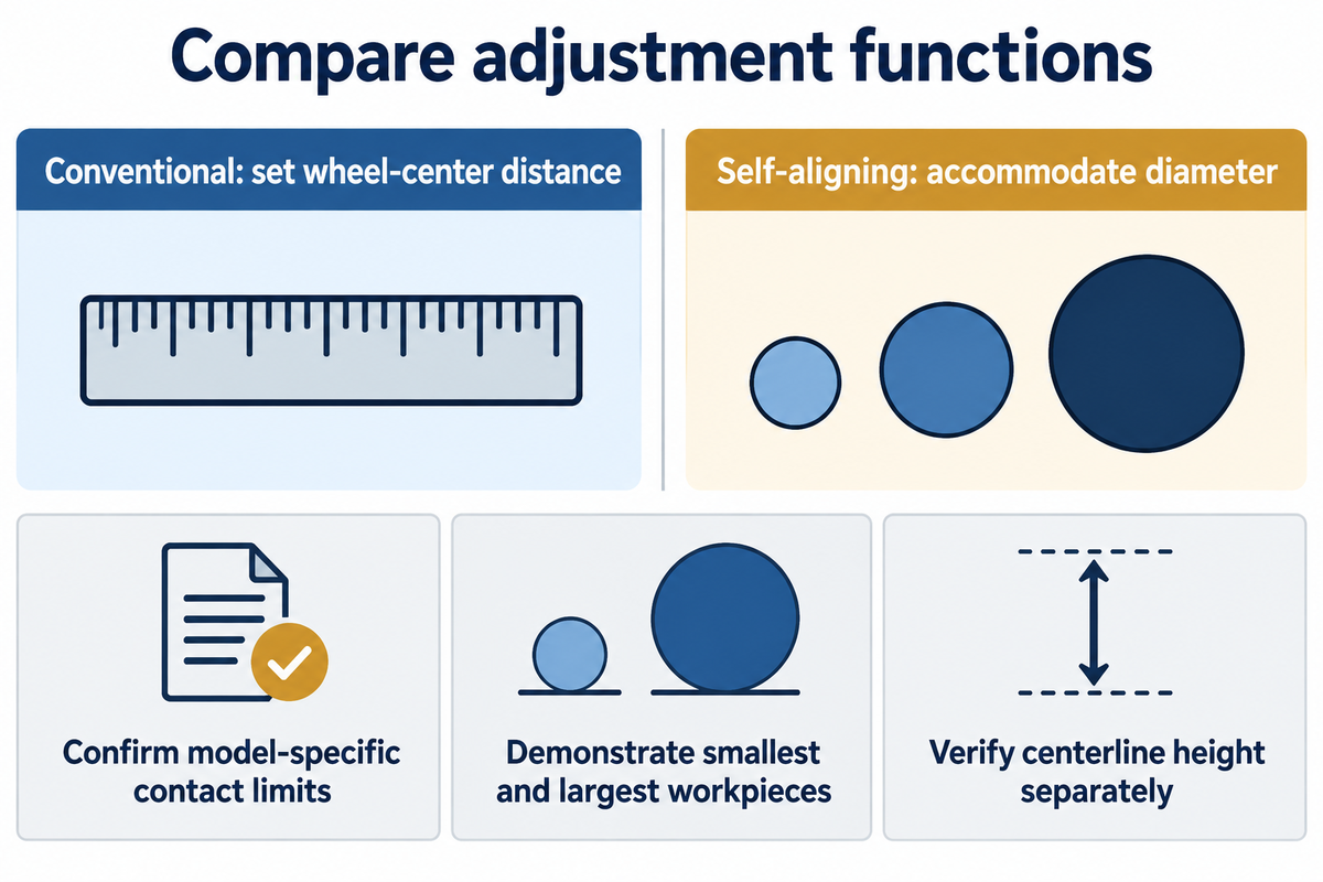
Self-aligning turning rolls allow the wheel assemblies to be adjusted for different diameters. Conventional designs require the user to set the wheel-center distance to a selected value. Compare the setup work involved in switching between your actual vessel sizes, along with the approved contact and load limits. Automatic diameter accommodation doesn’t prove better weld quality or eliminate axial drift.
Key Plant describes self-adjusting wheel centers on its self-aligning range. IRCO separately advertises a constant, adjustable centerline on its self-aligning turners. These are manufacturer descriptions of particular designs. Check whether the quoted machine offers those functions rather than treating every self-aligning rotator as mechanically identical.
Does the rotator adjust automatically?
A self-aligning rotator can automatically adjust wheel contact as the vessel diameter changes, in the range defined by the seller. Other adjustments can be manual or require a powered function. Ask the seller to identify diameter accommodation, centerline height, section alignment and axial travel control. The word “automatic” doesn’t necessarily define which of those functions are automated.
Imagine a fabrication shop repeatedly making shells of one diameter. A conventional set may not need much changeover after the initial setup. A shop that’s projected to handle several diameters should request a demonstration using the smallest and largest planned workpieces. Record what adjustments the operator makes, and if a crane is needed for the demonstration; don’t let an unsupported setup-time saving be the basis for purchase.
No universal, verifiable, minimum diameter derating curve was located for this comparison. Request the selected model’s load versus diameter limits. Our self-aligning welding rotator guide addresses that machine family; the quotation should still specify the limits of the exact unit.
Measure handling time during that demonstration from the same starting and finishing conditions. A claim of “full control” isn’t corroborated by an assumed operator’s ability to make all necessary adjustments to perfect alignment.
Fit-Up and Anti-Drift: Choose the Needed Function
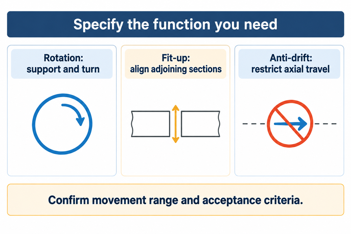
Fit-up equipment brings adjoining sections together for assembly. Anti-drift equipment is used to restrict unwanted movement in the axial direction during rotation. The main function of a turning roll is to support and rotate the workpiece. Choose the additional function from the task you need performed, then specify its movement range and acceptance criteria in the quotation.
Koike separates its specialty-roll products into fit-up and anti-drift categories. Aligning two shell courses involves considering available vertical and lateral movements, loaded adjustment conditions and how fit-up units coordinate with the turning set. A self-aligning wheel bracket alone does not establish those capabilities.
Axial control also deserves its own discussion. Koike Aronson’s published patent application US20110109030A1 describes changing idler orientation to produce corrective axial force, with sensing in some arrangements. It was published in 2011; it’s neither a new industry-wide standard nor Aubrik’s invention. The practical buying question is which drift-control mechanism the offered model uses and under what conditions it operates.
| Shop situation | Request | Confirm before buying |
|---|---|---|
| One assembled shell needs circumferential welding | Powered and idler roll set | Support reactions, contact limits and rotation duty |
| Adjacent sections need joint alignment | Fit-up movement suited to the joint | Adjustment directions and loaded movement range |
| Axial travel threatens seam position | Specified anti-drift function | Sensing, correction method and permitted travel |
| Several vessel diameters share one cell | Suitable diameter accommodation | Smallest diameter, contact geometry and changeover steps |
The fit-up rotator guide covers section alignment separately. Keep that discussion distinct from the acceptance test for axial drift during vessel welding. If hydraulic adjustment is offered, request its holding and isolation arrangements as part of the function review.
Tank Turning Roll Cost: Buy, Rent or Used
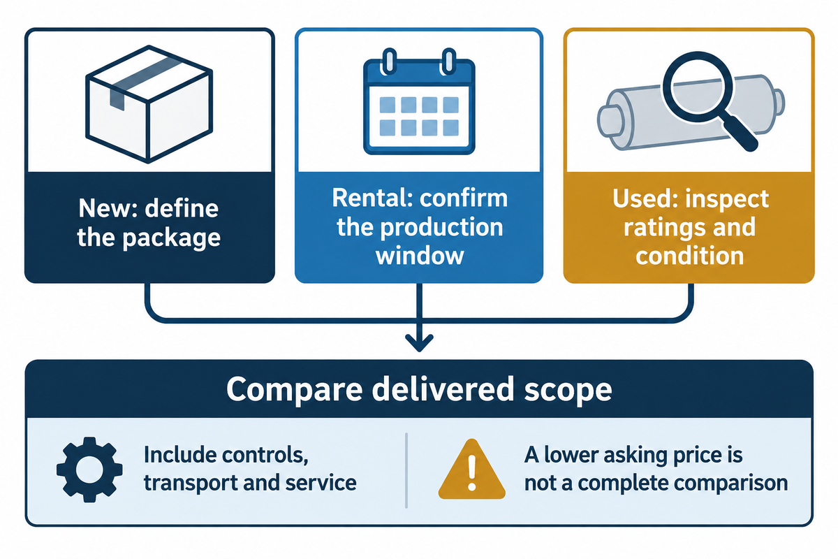
Tank turning roll costs should be compared for packages containing the powered unit, idlers, controls and any fit-up/drift-control options. When considering different offers, whether new, rental, or used, know that they may cover different equipment. Compare delivered scope and readiness for your vessel before treating a lower asking price as a saving.
On October 26, 2026, Baileigh’s RWP-220 page displayed an asking price of US$22,439. A Yoder listing for stock 23682, a Pandjiris Tanker 80, displayed US$4,950. These are separate listing examples, not equivalent machines or a market price range. The neighboring Yoder Aronson drive-and-idler listing requested a quote; the US$4,950 price didn’t belong to that set.
The Baileigh page also showed inconsistent load figures between description and specification. The discrepancy needs to be resolved using a recent model-specific document, and then the page can be used to select capacity. A purchasing manager comparing offers should request the same drawing, and vessel weights and duty in every inquiry, then itemize:
- Drive and idler quantities, controls, pendant and cables.
- Freight, unloading, installation and commissioning.
- Wheel condition, replacement parts and service access.
- Electrical compatibility and required cell integration.
- Rental duration, transport both ways and contractual return conditions.
Rental can be considered when a like set is available for the full production window, and is suitable for a defined project. Used equipment deserves a loaded demonstration and review of its ratings, manuals and maintenance condition. A low purchase price can lose its advantage if a discontinued wheel or drive component delays the next vessel. New equipment allows the buyer to specify the package prior to delivery, but the scope still needs to be defined.
Vessel Turning Roll Suppliers: Send the Right Inputs
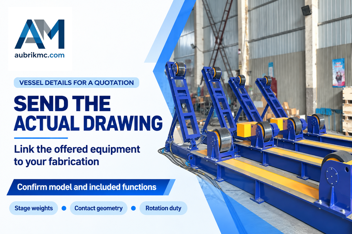
A vessel turning roll supplier needs to be given enough information to connect the proposed machine to the actual fabrication. A complete assembly drawing, stage weights and center-of-gravity locations, and the weld sequence need to be supplied. Ask for a written response linking the offered drive, idlers, wheels and controls to those inputs, rather than a capacity label alone.
For a maintenance engineer, spare-wheel availability could be the deciding factor. For a welding engineer, stable surface speed and access around the seam are more critical. Both questions should be addressed in the same package. Fill in the blank fields in your query with questions. Don’t assume a blank means the capability is present.
| Parameter | Project input | Why it matters | How to verify |
|---|---|---|---|
| Weight and center of gravity | Each assembly stage; units stated | Support reactions and drive demand | Drawing and load calculation |
| Diameter and shell | Minimum/maximum diameter, thickness, material | Contact geometry and local loading | Approved wheel/contact layout |
| Support locations | Axial spacing and permitted bands | Load distribution and seam access | Supplier-marked assembly drawing |
| Rotation duty | Surface-speed range, direction, duty cycle | Drive selection and welding requirements | Loaded acceptance test |
| Fit-up and drift control | Required movements and travel limits | Separates standard and optional functions | Function-by-function demonstration |
| Power and welding return | Supply details and welding-current duty | Separate supply, grounding and return circuits | Electrical and return-path design |
| Cell interfaces | Crane access, manipulator, purge lines | Clearance and utility management | Layout review and rotation trial |
| Service package | Wheel specification, spares and manuals | Maintenance and replacement planning | Written parts list and documentation |
Send these details in your inquiry to Aubrik welding rotators and turning rolls. Insist on confirmation of the model offered and the functions included. The checklist doesn’t verify inclusion of all functions.
Welding Cell Integration and Utility Requirements
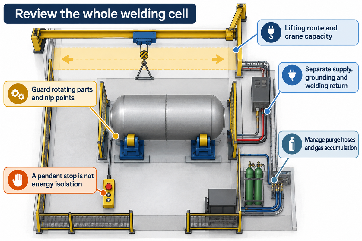
An order for turning rolls must account for the entire welding cell, including lifting, guarding, electrical, and rotating services. Check these interfaces before shipping. A vessel for turning rolls may exceed the limits of the available crane, or may put hoses and cables in an undesirable conflict with the welding head.
A Fabricator case study of McAbee’s vessel project describes sectioning work around crane capacity and obtaining Ransome turning rolls for final assembly. It illustrates a separate lifting constraint and isn’t an example of Aubrik productivity. Another Team Industries case study describes purge hoses restricting pipe rotation. Both demonstrate that a roll rating alone doesn’t determine if a cell is ready.
On the shop floor, operator safety also includes the loading route and access around the rotating envelope. Address these questions in the layout before delivery. Discovering those layout problems with a vessel suspended over turning rolls wouldn’t be helpful.
In US general industry, OSHA 1910.212(a)(1) outlines guarding to protect from ingoing nip points and rotating parts. Plan the operator’s position, access and controls based on the actual layout. For servicing covered by the hazardous energy rule, a pendant stop isn’t a form of energy isolation.
“Push buttons, selector switches and other control circuit type devices are not energy isolating devices.”
Keep the supply, protective grounding and the current return path distinct in the design. OSHA 1910.254(c)(2) covers requirements for grounding and fixtures in a return circuit. Don’t assume roller contact or bearing contact provides a sufficient return; have the equipment supplier and electrical designer determine the path.
Both hose travel and gas buildup must be managed for purging. The UK Health and Safety Executive’s guidance on welding asphyxiation hazards covers displacement of oxygen in fabrications and adjacent spaces. The purge gas does shield but can still displace oxygen. Evaluate ventilation and monitoring of the atmosphere and controls for entry to that space. This technical guidance isn’t mandating every open roll station be considered a confined space.
The required electrical standard and edition must be stated in the purchase specification. The EVS catalogue for EN 60204-1 covers the 2025 amendment and 2026 corrigendum. Its scope doesn’t cover all non-electrical machinery hazards. A standard reference on a quotation is therefore one part of the review, not evidence that the completed installation meets every requirement.
Frequently Asked Questions
How do you use turning rolls?
Use turning rolls with an approved support layout, suitable contact areas and a load within the ratings of the complete configuration.
Follow the machine instructions for loading and settings, check clearances and utility routing, and confirm controlled rotation before welding. Keep people clear of the moving vessel and roller nip points. Check that temporary attachments remain clear throughout rotation and that the support positions match the approved layout for the current assembly stage.
How is the speed controlled?
Speed control normally acts through the powered unit’s drive, with the available adjustment and feedback specified for each model.
A variable frequency drive or another variable speed arrangement may be offered. Specify the surface-speed range needed at the vessel, then verify stable loaded operation at the lower end of that range. Include the workpiece diameter in the acceptance record, because a shaft-speed indication alone doesn’t describe travel at the weld. Confirm how the operator changes the setting.
What types of welding can this equipment support?
Turning rolls can support circumferential arc welding when the vessel geometry, welding procedure and cell arrangement suit rotation. The rolls position the workpiece; they don’t select the welding process.
Confirm coordination with the welder or automated welding head, including travel speed, seam access and any required start or stop signals. Where an automated head is used, agree which controller commands motion and how the system responds to an interruption. Keep the welding procedure tied to the actual material and joint.
Do I need a positioner instead of turning rolls?
Choose from the motion and workholding required. Turning rolls carry cylindrical objects on their outside surface. A positioner can hold a fabrication on a fixture or table and may provide tilt. Compare the actual joint access and load arrangement before choosing.
Can I add an idler to increase the rated capacity?
An additional idler can provide another support, but it doesn’t automatically increase the approved capacity of the existing set.
The manufacturer must confirm load sharing, contact geometry and the powered unit’s ability to rotate the vessel. With more than two support stations, stiffness and alignment influence the reactions. Obtain an approved layout and revised operating limits before using the extra unit to carry a heavier assembly; the simple two-support calculation no longer describes the full arrangement.
Can a seller’s used set be suitable for my vessel?
A used set can be suitable when its documented ratings, diameter limits, condition and controls match the vessel and duty. Verify the included drive and idlers, inspect wear components, and arrange a representative loaded demonstration before accepting the equipment for production.
What should I check for a small vessel on self-aligning rolls?
Check the exact model’s minimum diameter and approved load at that diameter, along with wheel contact and clearances.
Ask whether the vessel fully engages the intended wheels and whether the bracket geometry remains within its operating limits. Include the smallest shell in the supplier’s drawing review and demonstration. There’s no verified universal derating percentage in the sources used here, so a larger nominal capacity shouldn’t replace the manufacturer’s model-specific answer.
References & Sources
- Examples of Static Equilibrium OpenStax, University Physics Volume 1.
- How one of the largest pressure vessels in the world was made The Fabricator.
- Weld-positioning case at Team Industries The Fabricator.
- General requirements for all machines US Occupational Safety and Health Administration, 29 CFR 1910.212.
- The control of hazardous energy US Occupational Safety and Health Administration, 29 CFR 1910.147.
- Arc welding and cutting US Occupational Safety and Health Administration, 29 CFR 1910.254.
- Asphyxiation hazards in welding and allied processes UK Health and Safety Executive.
- EN 60204-1 consolidated standard catalogue entry Estonian Centre for Standardisation and Accreditation.