Get in Touch with Aubrik Company

Quick specs for this guide
Decision unit: accepted weld output on comparable parts. Trial sample: three representative part families, repeated across lots or shifts. Routes compared: workpiece handling, fixed robotic cell, collaborative robot, and sensor-assisted control. All cost figures below are illustrative, not Aubrik performance data.
Decision unit: accepted weld output on comparable parts. Trial sample: three representative part families, repeated across lots or shifts. Routes compared: workpiece handling, fixed robotic cell, collaborative robot, and sensor-assisted control. All cost figures below are illustrative, not Aubrik performance data.
Automation in welding is easier to define than to implement. A camera may be able to find a seam, but a queue of untacked assemblies will still starve the cell. A fast robot may be able to repeat a path, but an inspector may still reject the joint. So the key question a fabricator should ask is which station limits the accepted output of its own parts.
Welding automation trends in 2026 center on sensing, flexible cells, workpiece handling, and weld records. The International Federation of Robotics counted 542,000 industrial robot installations worldwide in 2024 across all applications, not welding alone. Choose a pilot by measuring accepted output and the constraint around the arc.
In brief
- The robot installation figure often quoted for 2024 covers all industrial applications; it isn’t a welding adoption rate.
- Vision and seam tracking work in configured systems, but still need controlled fit-up, process settings, and inspection.
- A positioner or rotator can be the better first purchase when access and handling delay the weld.
- Compare cost per accepted, comparable weld output after loading, changeover, inspection, and rework.
Aubrik manufactures welding equipment in Wuxi, China. Their product listings describe the equipment and its available configurations, but a performance claim for a buyer’s job requires a representative part trial.
Which welding automation trends matter to a fabricator in 2026?
Different problems require different solutions. A shop with variable fit-up should start with fixturing and gaging, while a shop with repeatable assemblies and idle welding time may have a case for a robotic cell.
The International Federation of Robotics reported 542,000 industrial robots installed worldwide in 2024. It should be understood, however, that while some welding applications may have a positive return on investment (ROI), this industrial robot count does not show how many welding robots were installed. The report should be used to understand the deployment of industrial robots, not to create a sales forecast for the welding automation market.
There are several ways to interpret a new investment in welding automation and robotics. Automated welding systems control part or torch motion. A robotic welding system, on the other hand, adds a programmable arm to a welding system. Both are systems, but the first type of automation a shop needs may be a fixture or positioner. Compare automation solutions against a measured station problem before asking vendors for a machine category.
The welding industry includes high-volume automotive lines as well as heavy fabrication with changing assemblies, and welding technology requirements vary across those settings. A process that’s suited to welding a repeated car body joint doesn’t automatically apply to a large vessel. Specify which types of welding the parts require, along with joint access and batch mix, before using a trend headline to set the equipment budget.
| Route | Problem it can address | What the pilot must prove |
|---|---|---|
| Positioner or rotator | Access and part orientation | Safer handling and a useful weld position on the real assembly |
| Fixed robotic cell | Repeatable torch path on suitable parts | Accepted output after loading, setup, and inspection |
| Collaborative robot | Programming and changeover friction on some smaller batches | Cycle time, reach, fit-up, and application-specific safety controls |
| Sensor-assisted cell | Measured joint or part-position variation | Correction range and weld acceptance on buyer parts |
Where do vision and seam tracking improve a robotic welding cell?
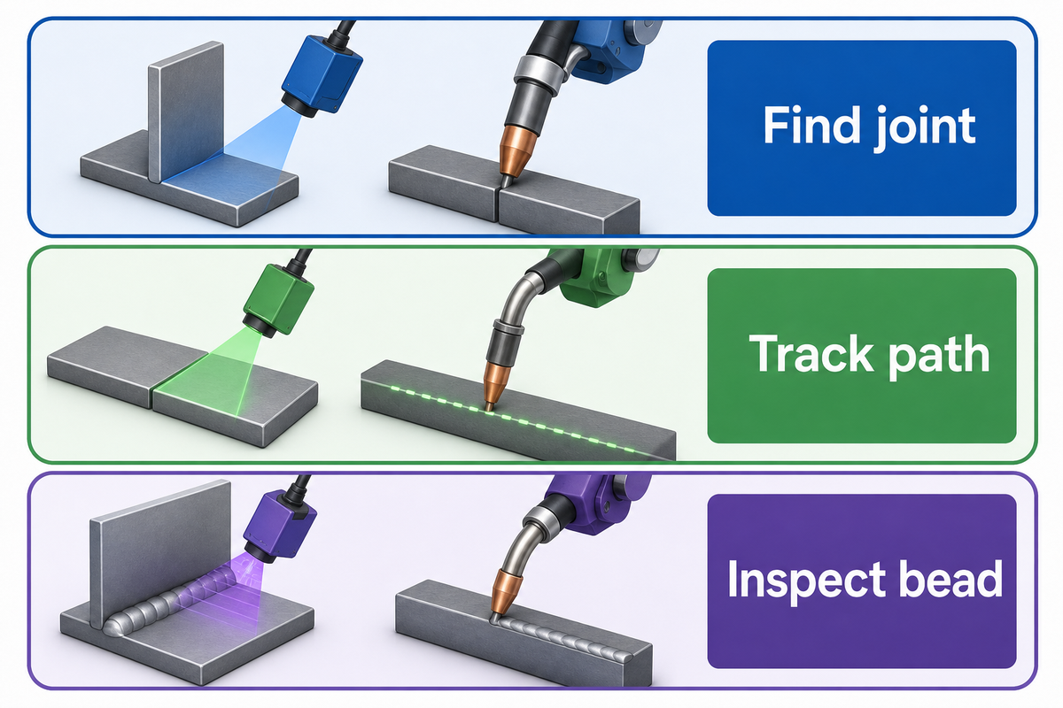
Vision can locate a joint before welding, seam tracking can adjust a configured path during welding, and inspection sensors can measure features of the finished bead. These are system-specific capabilities. The supplier must still show the variation it can handle, the calibration it needs, and the weld quality achieved on the buyer’s material and joint.
An article published by the American Welding Society discusses seam finding, tracking and bead measurement as three separate functions. Jeff Noruk, president of Servo-Robot Corp, describes robots repeating a taught path without detecting joint variation. A sensor addresses part of that gap; it does not turn an unqualified procedure or loose fixture into a sound weld.
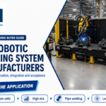
Aubrik lists robotic welding machines, cells, and cobot welding routes. Along with those configurations, the company offers vision and seam-tracking options. Don’t assume a route contains every possible option. Ask which sensor and software package and guarding option are included in the quote. Then, run the part through the configuration to see if it’s feasible.
Ask the vendor what the actual measurement and logging is for the controller during real-time correction. An artificial intelligence feature may classify a joint or propose a path, while a conventional sensor may follow a narrower rule. Vendor labels such as “AI-powered welding” and “advanced welding” do not answer that engineering question. Ask for a before and after trace of the welding tasks (and software) and the operator’s action when the correction limit is reached.
How much part variation can seam tracking actually handle?
The answer is a measured range for a joint, material, fixture and process, not a Universal Tolerance. Define the range for expected misalignment, gap and variation. Record what inspection finds after welding, and where the sensor finds the joint, and where correction stops. For lack of specification of the test range by the vendor, consider it an unverified option in the business case.
- Present the part — record fit-up and fixture position.
- Measure the joint — log what the sensor locates before the arc starts.
- Correct the path — record the commanded offset and any stop limit.
- Verify the weld — inspect against the drawing and applicable procedure.
Can a welding cobot handle high-mix parts better than a fixed cell?
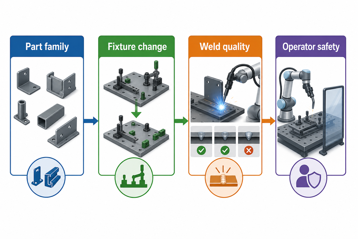
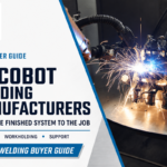
In small batch production, where similar welds occur in repetition, collaborative robots (cobots) can be an attractive solution. Fixturing and programming changes can be a barrier. A fixed automated welding cell can work when a part family repeats and loading overlaps welding. Neither route has an automatic advantage. Consider reach, payload, access to the welding torch, the changeover, the accepted weld quality and the remaining work for the operator on the real batches to be welded.
A shop that produces structural brackets may have five different assemblies, but may have the same short weld around a common feature. A reusable fixture and a trial on that repeated feature may justify partial automation. A different, more awkward weld may remain fully manual. This hypothetical bracket example illustrates a possible benefit of partial automation, but it doesn’t mean that a cobot is justifiable for every high mix / low volume shop. An Eng-Tips Practitioner discussion raises the same possibility as an anecdote; it provides no transferable batch threshold.
A cobot welder quote should account for the tools and fixtures that experienced welders still change. Robotic arms may take over repetitive tasks, but finding skilled welders is only one part of a staffing plan. The lack of skilled welders doesn’t mean there’s no need for welders and other welding professionals to establish work procedures and supervise and evaluate work. Estimate labor costs based on actual time spent doing preparation, supervision, maintenance, and welding, not based on a projected headcount reduction.
The safety review should consider the entire welding process. The U.S. Occupational Safety and Health Administration robot guidance calls for hazard analysis around robotic systems. Just because a robotic arm is limited to a certain force doesn’t eliminate exposure to a live torch, arc radiation, spatter, hot parts, and fumes. Inquire of the integrator how the proposed cell addresses each of these hazards and where the operator stands during loading and welding. OSHA’s welding-fume guidance is a prompt to assess exposure and controls, not a plant-specific ventilation specification.
Cobot route
- Measure programming and fixture changes per batch.
- Check reach and access on the largest representative part.
- Specify arc, fume, and hot-part safeguards.
Fixed cell route
- Measure repeated output across the intended part family.
- Time loading, unloading, and fixture changes.
- Verify the cell’s guarding and operator tasks.
Why are weld records and inspection moving into cell selection?
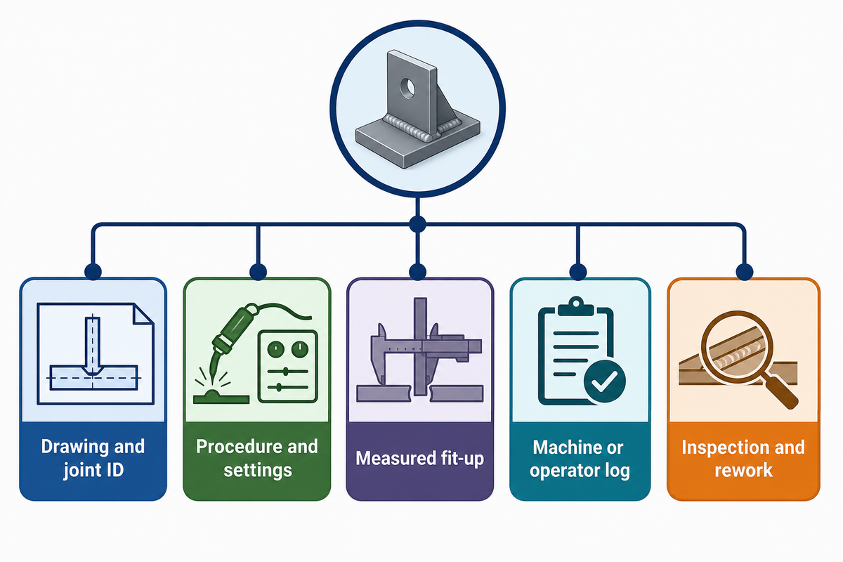
An acceptable weld is a quality result. Buyers need the procedure and parameter record, a link from each part to inspection, and a count of rejected or reworked joints. The method of inspection should be aligned to the drawing, code, and standards. A camera or other vision system alone shouldn’t be the only means of proving full conformance and integrity.
Robot coordinates can repeat while the torch center point, wire position, or fixture changes. JR Automation explains this tool-center-point problem from an integrator’s perspective. It’s a reason to test and inspect, not an independently measured defect-rate claim. Panasonic’s Bead Eye documentation explicitly limits its geometry-based detection for internal defects and insufficient penetration; that product-specific limit illustrates why the buyer must specify the required inspection method.
Five linked records are requested for each trial part: its drawing and joint ID; approved welding procedure and setting changes; measured fit-up and fixture condition; machine or operator log; and inspection result, including any rework. If an attractive bead image is the only information provided by the supplier, the purchasing committee has no proof of accepted output.
An Internet of Things dashboard might make those records easy to obtain, but connectivity is a transport mechanism, not an inspection result. A screen that only reports machine uptime cannot tell quality staff which joints passed.
Rather than accepting every camera image as a pass, quality control should connect those records to product quality. A buyer’s demand for high-quality joints and demand for precision must become drawing tolerances and a stated inspection method. An inspector’s understanding of the welding process may play a role when a bead looks sound but the specified examination asks a different question.
When should a positioner, rotator or manipulator come before a robot?
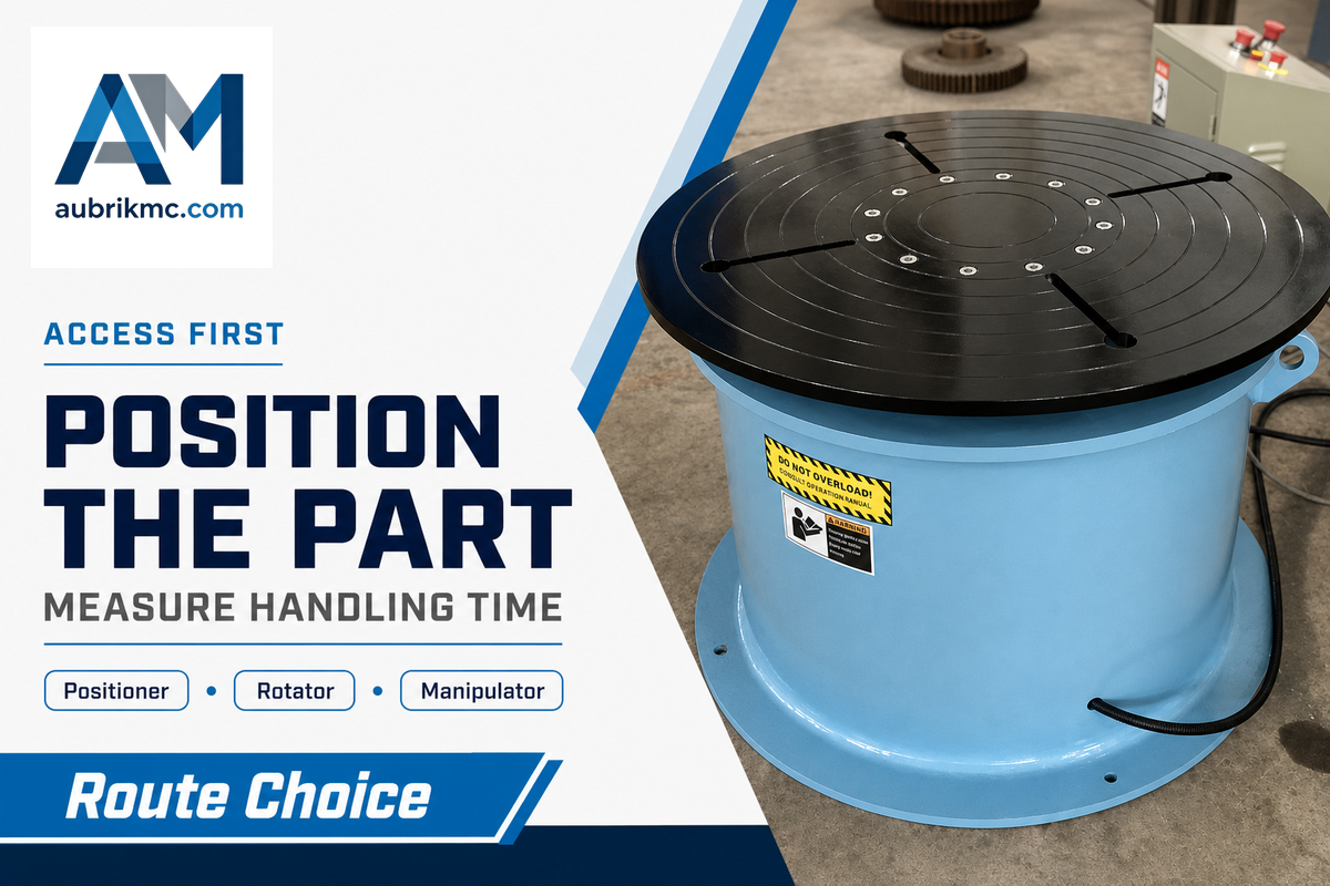
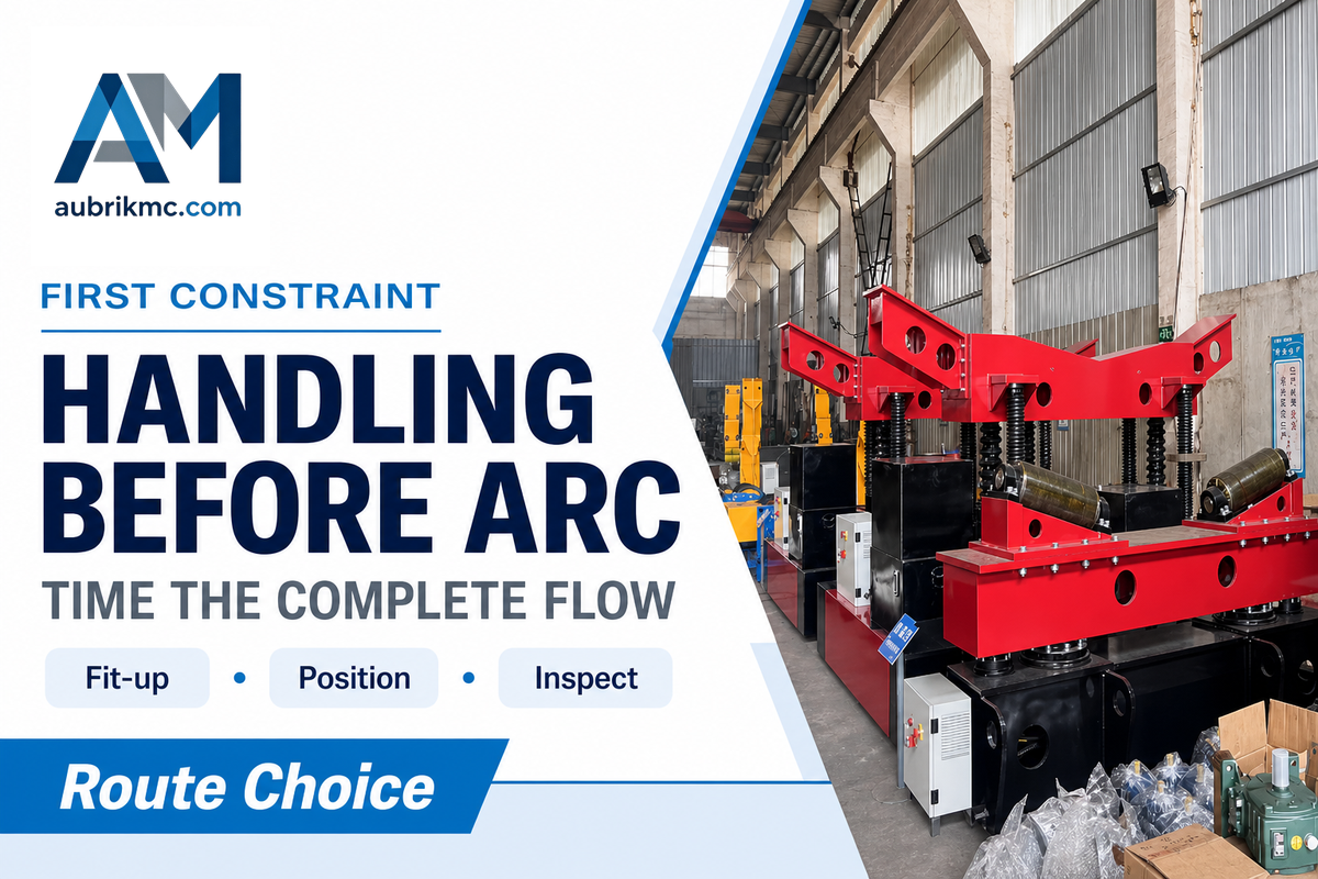
Decide on a route after timing how the workpiece moves to a weldable position. A positioner can reorient a heavy assembly and a rotator can turn a cylindrical workpiece. A column-and-boom manipulator can position a torch along a long joint. A robot plus positioner can also be used. The optimal sequence depends on several factors including the weld position, access, fixture changes, and accepted output for the part family.
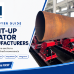
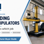
Here are three typical examples. A turning roll may support the rotation of a long pipe joint, and a positioner may also enable access to a desired position before a robot’s path becomes the limiting factor. A column-and-boom manipulator may position the torch to the welding joint while the work turns on a vessel seam. The aforementioned products may be listed by Aubrik, but that doesn’t mean that the buyer’s assembly will experience a positive impact on productivity.
The routes can be combined. FANUC’s 2026 dual-station positioner example pairs loading on one side with robotic arc welding on the other. It’s a named industry configuration, not an Aubrik specification. The Welding Institute notes that welding position also changes process economics, so the trial should record both handling time and weld position. A small batch can still justify a robot if quick tooling and recurring weld features make the complete cycle work.
Use the Seven-Station Weld Capacity Map before choosing equipment
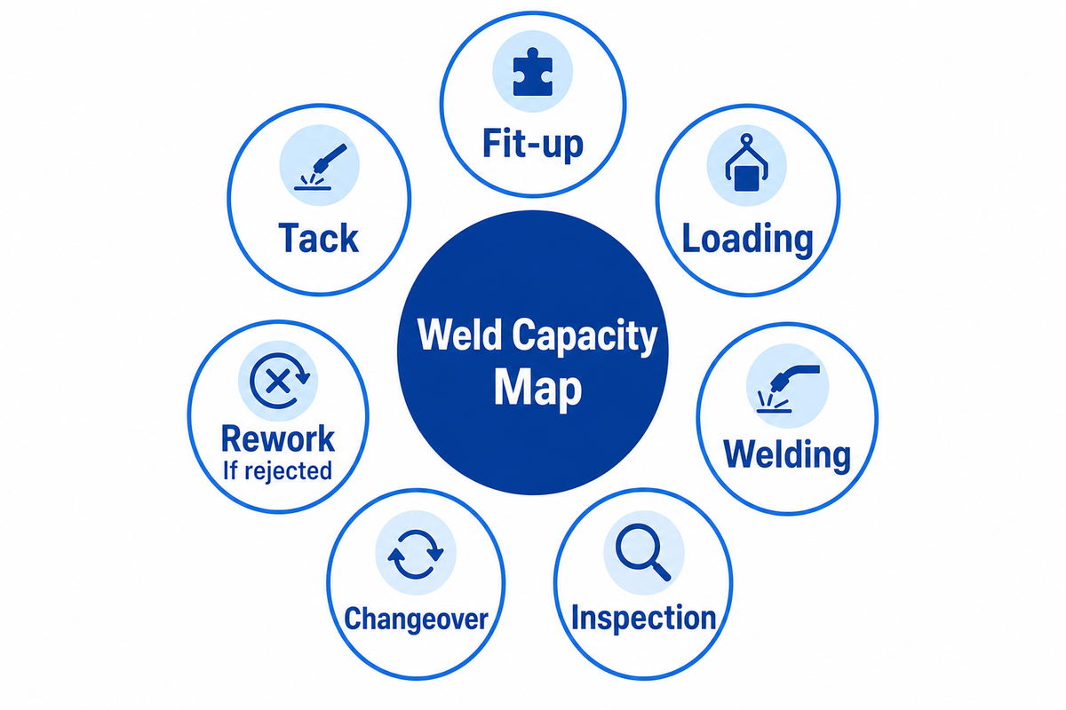
The “Seven-Station Weld Capacity Map” is a buyer measurement checklist for fit-up, tack, loading, welding, inspection, changeover, and rework. This example is an original aid, not an industry standard or Aubrik field dataset. Time each station on three representative part families and then repeat the sample across lots or shifts to confirm stable results.
The map allows plant management, quality and procurement to identify the required changes to a proposed cell and agree on the scope. Use actual timestamps and accepted-part counts. Don’t accept the supplier’s ideal cycle time as the baseline. The map prevents a fast arc from hiding a slow queue.
This is the stage of robotics/automation planning where they begin to engineer the production system. Modern welding automation can move a torch accurately while the surrounding welding operations remain manual. Time those operations separately. The map helps compare automation systems and smaller automation tools against the station that truly delays accepted parts, instead of treating every welding activity as a robotic task.
| Station | Measure | Possible response | Observation that would disprove it |
|---|---|---|---|
| Fit-up | Gap spread and minutes per part | Fixture or part preparation | Fixture adds time without reducing variation |
| Tack | Tack minutes and position errors | Repeatable tack plan | Downstream corrections stay unchanged |
| Load and present | Lift, clamp, and orientation minutes | Positioner or parallel loading | Cell still waits for the next part |
| Weld | Arc-on and interruption minutes | Programmed path or sensing | Accepted parts per shift do not rise |
| Inspect | Queue and inspection minutes | Record and inspection planning | Inspection backlog grows after pilot |
| Changeover | Fixture and program minutes per lot | Reusable tooling or programming | Total shift output falls at actual mix |
| Rework | Rejected joints and repair minutes | Process control and root-cause action | Reject rate or repair burden persists |
Is welding your real bottleneck?
Compare the queue before each station to the accepted parts that leave the last one. Suppose a trial cuts arc-on time, but fit-up still releases only one assembly at the old pace. The extra robot capacity stays idle. This is a flow illustration, not an Aubrik case.Research by the National Institute of Standards and Technology indicates that variability in product mix causes bottlenecks to also vary, another reason to time different part families.
Calculate cost per accepted weld metre, not arc speed alone
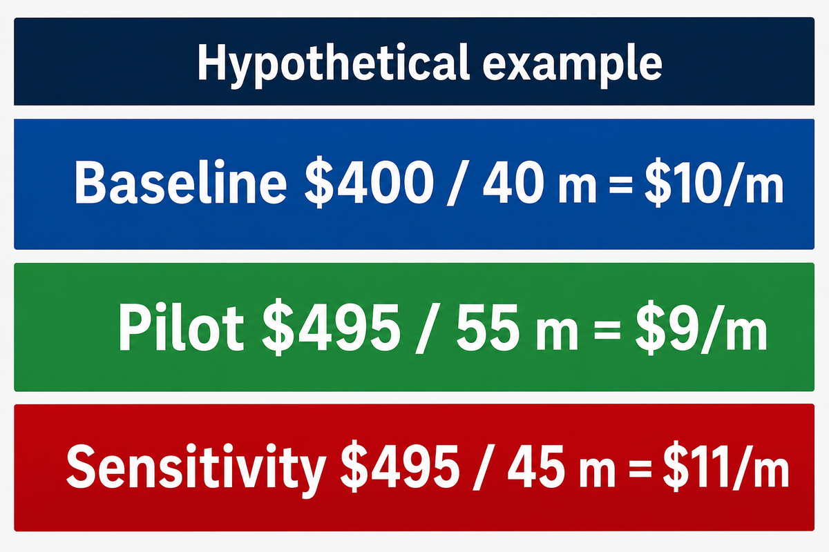
For similar joints, divide fully loaded cost of a production period by its accepted weld metres. Include labour, equipment ownership, consumables, inspection and rework. A lower cost per metre is meaningful only when joint family, material, weld size or deposited mass, quality requirement, and production mix are comparable.
Cost per accepted comparable weld metre = (labor + equipment ownership + consumables + inspection + rework) ÷ accepted weld metres. A finance team can replace the examples with plant records. If the jobs produced materially differ, compare cost per accepted comparable part or per accepted deposited mass; The Welding Institute’s fillet-weld discussion shows why weld size changes material and cost.
| Input | Current route | Pilot route |
|---|---|---|
| All-in shift cost | $400 | $495 |
| Accepted weld length | 40 m | 55 m |
| Cost per accepted metre | $400 ÷ 40 = $10 | $495 ÷ 55 = $9 |
The pilot appears cheaper by $1 per accepted metre in this contrived example, notwithstanding its higher shift cost. If inspection or rework reduces pilot output to 45 accepted metres, for example, the cost becomes $495 ÷ 45, or $11 per metre, and the decision would reverse. Finance should also model the capital, service and utilization costs over the intended ownership period. A payback estimate built on torch travel time alone doesn’t capture all the variables.
When vendors quote a growth rate for a machine category, keep that figure outside the plant calculation. No market estimate can replace accepted weld output, a like-for-like comparison, and the actual cost ledger for the job in question. Whether a faster route is of commercial benefit depends on those inputs.
Market size is similarly irrelevant to the unit-cost line: a large sector may still leave a particular plant with too little repeatable work for its proposed cell. Test the quoted route at the expected utilization before the capital is committed.
What evidence should a welding automation supplier produce in a sample run?
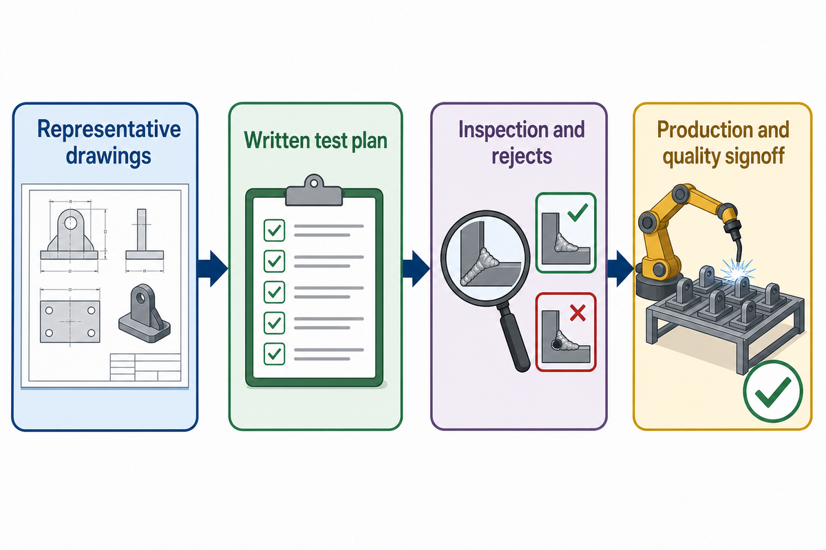
A useful sample run welds the buyer’s own representative parts under a written test plan. It records setup, changeover, the complete seven-station flow, process settings, inspection, rejects, operator work, and safety controls. Procurement should establish pass/fail criteria before the demonstration, and have quality and production sign off on the results separately.
Send three drawings to demonstrate the range of joint geometry, size, material and expected fit-up. Provide the intended part mix and expected lot sizes. A polished demo for an ideal part answers a different question.
| Evidence category | Evidence to record | Pass rule to set before the run |
|---|---|---|
| Production | Fit-up, tack, loading, arc, inspection, changeover, and rework time | Accepted parts per shift at the planned product mix |
| Quality | Drawing, procedure, parameter log, inspection result, reject reason | Buyer-defined acceptance on each sampled joint |
| Safety | Application risk review, guarding, arc, fume, and hot-part controls | Controls agreed for the actual site and task |
| Maintenance | Sensor cleaning, calibration, spares, fault recovery, training | Support and recovery plan accepted by the buyer |
| Procurement | Included options, capital, service, and ownership costs | Quoted configuration matches the tested one |
| Process engineering | Joint range, fixture datum, sensor correction limits | No unexamined joint variant in the proposed part family |
| Data and traceability | Part ID linked to parameter and inspection exports | Buyer can retrieve a complete record by part ID |
| Training | Changeover, fault response, and parameter authority | Named site staff can run and recover the quoted cell |
| Finance | Accepted-output cost at the planned utilization | Business case holds at buyer-recorded cost and mix |
A supplier demonstration and a welding procedure qualification are two separate activities. ISO 15614-1:2017 describes procedure testing within its scope, while ISO 14732:2025 addresses qualification of operators and weld setters for mechanized and automatic welding. Clarify which standards and contractual requirements apply to the project, who has authority to change parameters, and what records the buyer will receive. ISO 10218-2:2025 covers robot applications and cells; its publication does not by itself establish a universal legal deadline for every plant.
If you doubled welding capacity tomorrow, where would the next bottleneck appear?
Measure the other 6 stations before answering. Inspection may queue up, loading may leave the robot waiting, or rework may consume the extra weld output. Repeat the test across lots or shifts before assuming that one short demonstration is stable capability. National Institute of Standards and Technology process guidance separates process stability over time from a single favorable sample; it’s general statistical guidance, not a welding acceptance code.
What should fabricators watch next in adaptive welding?
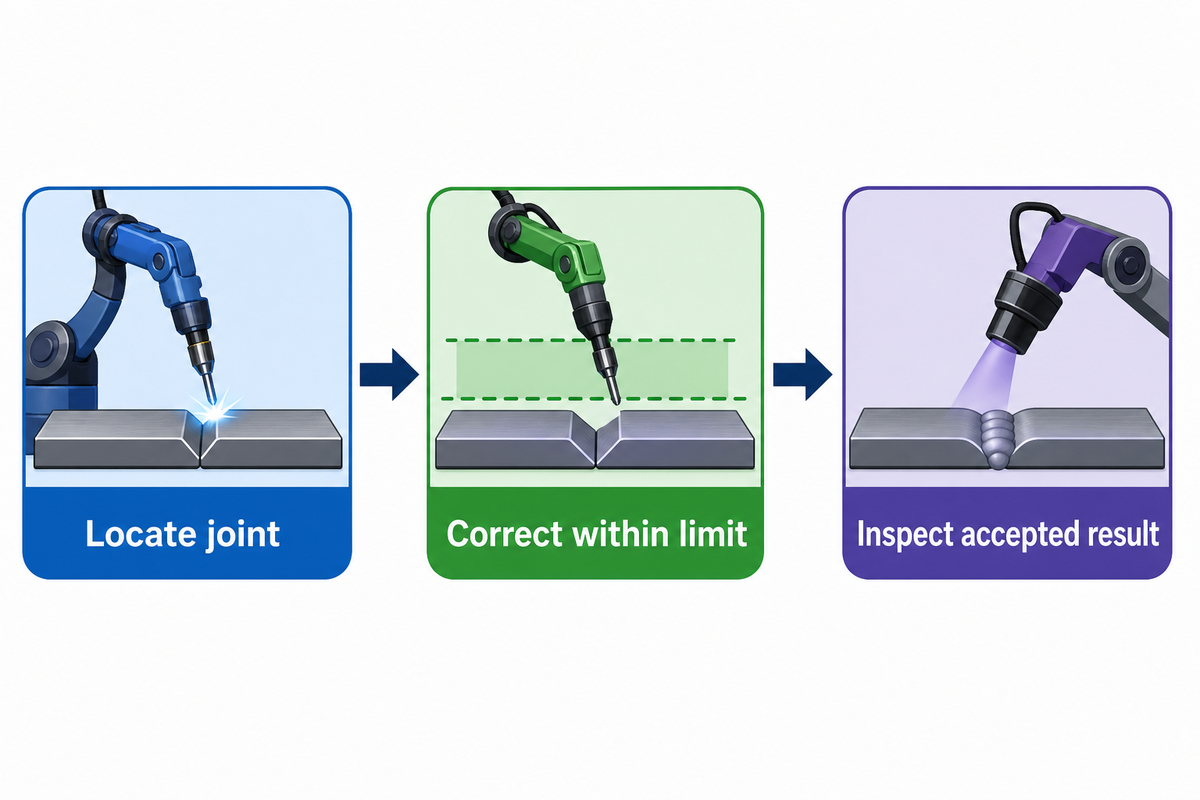
Look for evidence that a system can locate varying joints, correct a path within stated limits, and connect the outcome with inspection records. This is a stronger buying signal than a system being called “autonomous.” An emerging method may be appealing and still not be able to demonstrate full competency for a large, reflective or changing assembly.
A September 2026 American Welding Society discussion describes specific adaptive guidance examples and the continuing difficulty of proving fully autonomous operation over time. Obtain the tested part envelope, a recorded correction limit, and repeated accepted results.
Autonomous welding is a useful research direction, but fully autonomous welding is a much stronger claim than a camera correcting one seam. The same distinction applies to arc welding robots sold with optional sensing. If a proposal promises autonomous welding operations, ask which decisions the software makes, which remain with the operator, and how exceptions are recorded. Assess robotics and AI as they’re presented in the system, not as blanket properties of every component of the system.
Key takeaway
Buy the route that increases accepted output across the whole production flow. Time three representative part families, test the quoted configuration, and let production and quality judge the same sample run.
Frequently asked questions about welding automation
What is welding automation?
Read answer
Welding automation uses equipment to move a torch or workpiece, control a welding sequence, or guide a robot with sensors. It ranges from a positioner that keeps a part in a useful orientation to a programmed cell. The level of automation doesn’t itself prove that a weld meets the drawing, procedure, or inspection requirement.
What are the benefits of welding automation?
Read answer
The benefit depends on the station that limits accepted output. A positioner may reduce handling, while a robotic cell may repeat a proven path across similar parts. A cobot may ease changeover in some batches. Measure operator work, inspection, rework, and accepted output before assigning a gain to the machine.
What are the challenges associated with welding automation?
Read answer
Variable fit-up, poor access, changing part families, and weak fixtures can consume the time a fast path saves. A cell also needs process control, application-specific safety measures, fume assessment, inspection, training, and support. A representative-part trial can reveal these limits before the purchase decision. Record the limiting condition and repeat the trial across more than one batch.
Can automation solve the welder shortage?
Read answer
Automation may shift repetitive motion from people to equipment. It still needs people who can prepare parts, set and control welding procedures, maintain fixtures, supervise the cell, and judge quality, even amid a shortage of skilled welders. A staffing plan should count those tasks rather than assume a universal number of welders can be replaced.
Which industries use welding automation?
Read answer
Pipe fabrication, structural steel work, pressure-vessel production, and other heavy fabrication can use mechanized handling or robotic welding where part geometry and volume suit the process. The right level of automation varies by joint, part mix, safety requirements, and inspection basis.
Is robotic welding the same as automated welding?
Read answer
Robotic welding is one type of automated welding. Automation also includes mechanized part movement, such as positioners and rotators, and controlled torch movement by manipulators. A plant can combine these routes or automate only a repeatable portion of the job.
Bring your parts and measurements to the discussion
Aubrik can discuss a positioner, rotator, manipulator, robotic cell, or combined route against three representative drawings. Share the Seven-Station timings, required inspection basis, and target production mix so the proposed configuration can be tested against your actual constraint.
Evidence Note: This article cites publicly available manufacturer pages to describe offered product lines, relies on external sources for technical context, and includes an explicitly hypothetical cost example. It doesn’t present the Seven-Station Map as an accepted industry standard, nor do the sample numbers represent customer experience. Site-specific safety, welding procedures, and inspection acceptance require project review.
References & Sources
- International Federation of Robotics, World Robotics 2025 release
- American Welding Society, welding automation and inspection
- U.S. Occupational Safety and Health Administration, robot safety guidance
- U.S. Occupational Safety and Health Administration, welding fumes
- The Welding Institute, weld design and position
- National Institute of Standards and Technology, product mix and bottlenecks
- International Organization for Standardization, ISO 15614-1:2017
- International Organization for Standardization, ISO 14732:2025
- International Organization for Standardization, ISO 10218-2:2025
- National Institute of Standards and Technology, process stability guidance
- American Welding Society, adaptive welding automation