Póngase en contacto con la empresa Aubrik

Guía de la máquina de soldadura de paneles de membrana para el control del proceso y la calidad

Guía de producción de paneles para calderas
Actualizado en julio de 2026
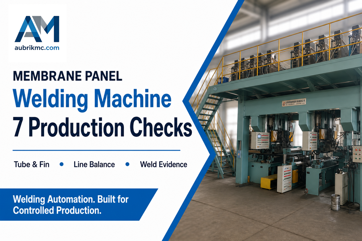
Una máquina de soldadura de paneles de membrana es la estación de unión de un sistema de producción de tubos y aletas más amplio. Puede coordinar el movimiento de soldadura y aplicar de manera repetible los parámetros del proceso, pero no puede corregir materiales sin verificar, un armado y ajuste deficientes, un procedimiento inadecuado, una inspección tardía ni una descarga bloqueada. Por lo tanto, para fabricar componentes estructurales de calderas de buena calidad, la planificación debe abarcar desde la liberación de los materiales hasta la entrega final, en lugar de basarse únicamente en la cantidad de antorchas o la velocidad de soldadura.
Respuesta rápida: defina el rango de productos, apruebe el armado y ajuste de tubos y aletas, trabaje conforme al procedimiento de soldadura calificado aplicable, inspeccione tanto las soldaduras como la geometría del panel y pruebe el flujo de producción completo durante la aceptación. La capacidad útil de la línea está determinada por el punto de control repetible más lento con la combinación real de productos.
En la práctica, la máquina de soldadura de paneles se encuentra entre la preparación y la inspección dentro de una línea de producción más amplia; las juntas de los extremos de tubos o tuberías pueden procesarse en otra estación.
1. Separe las tres capas de control.
Los ajustes de la máquina, la calificación del procedimiento y la aceptación contractual están relacionados, pero no son equivalentes.
Los ajustes de la máquina, la calificación del procedimiento y la aceptación contractual están relacionados, pero no son equivalentes.
2. Mida siete puntos de control de la producción.
La preparación, el armado y ajuste, los consumibles, la inspección, la reparación y el manejo pueden limitar la producción antes que el recorrido de soldadura.
La preparación, el armado y ajuste, los consumibles, la inspección, la reparación y el manejo pueden limitar la producción antes que el recorrido de soldadura.
3. Diagnostique con base en evidencia.
Revise los materiales y el armado y ajuste, los registros del proceso y las dimensiones posteriores a la soldadura antes de cambiar un ajuste.
Revise los materiales y el armado y ajuste, los registros del proceso y las dimensiones posteriores a la soldadura antes de cambiar un ajuste.
4. Compre resultados demostrados, no promesas.
La RFQ y la FAT deben normalizar la combinación de productos, los supuestos sobre turnos, los criterios de inspección y los registros de entrega.
La RFQ y la FAT deben normalizar la combinación de productos, los supuestos sobre turnos, los criterios de inspección y los registros de entrega.
Qué controla una máquina de soldadura de paneles de membrana y qué no controla
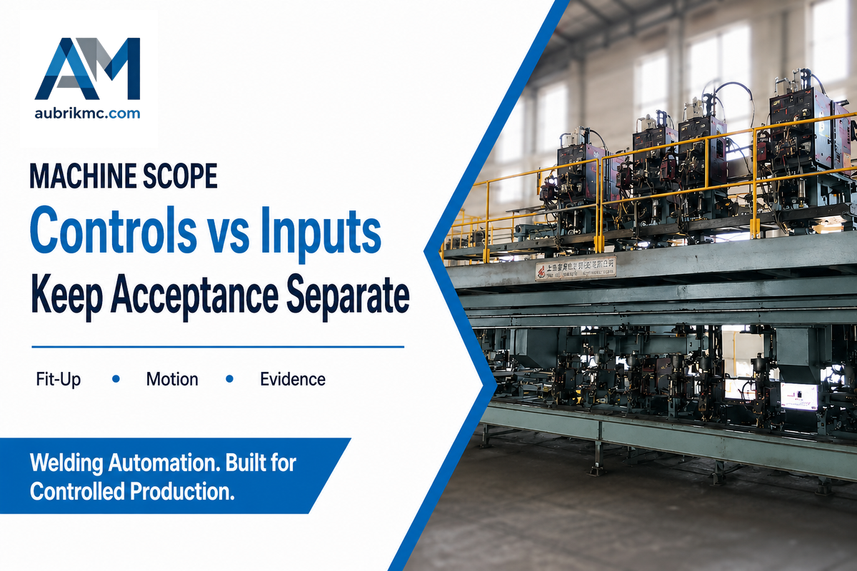
El conjunto preparado de tubos y aletas se desplaza, sujeta, energiza y suelda dentro del rango de diseño de la estación. Los controles del sistema de producción circundante determinan si el conjunto era apto para soldarse y si el panel terminado es aceptable. Considerar ambos aspectos como responsabilidad de una sola máquina oculta el origen de la variación.
El registro público de ASME correspondiente a la edición 2025 de la Sección IX del BPVC describe las reglas de calificación de los procedimientos y del personal de soldadura exigidas por otras secciones del BPVC. No proporciona una receta de ajustes para paneles de membrana. Esta distinción es importante: los equipos pueden reproducir parámetros aprobados, mientras que la WPS/PQR aplicable y los documentos contractuales definen la base calificada y aceptada.
| Elemento | Relación con la estación | Responsable principal | Liberación o evidencia |
|---|---|---|---|
| 1. Identidad de los materiales | Los tubos, las barras de aleta, el alambre de soldadura y el fundente liberados ingresan en la máquina; la estación no establece la trazabilidad. | Materiales y aseguramiento de la calidad | Registros de colada/lote e identificación de consumibles |
| 2. Geometría de tubos y aletas | Los dispositivos de sujeción solo pueden ubicar las piezas que estén dentro de la geometría para la cual fueron diseñados. | Ingeniería y preparación | Revisión del plano y verificación dimensional de entrada |
| 3. Estado de la superficie | El comportamiento del arco depende de la superficie preparada; el carro de soldadura no elimina todos los contaminantes. | Preparación y supervisión de soldadura | Criterio de limpieza documentado y liberación visual |
| 4. Armado, ajuste y sujeción | La sujeción mantiene inmóvil un conjunto, pero no puede hacer aceptables una separación o una alineación fuera de rango. | Estación de armado y ajuste | Verificación de la junta y la alineación antes de iniciar el ciclo |
| 5. Variables del proceso | La fuente de poder para soldadura, la alimentación de alambre, el recorrido y la posición del cabezal se controlan mediante la máquina dentro de los rangos configurados. | Ingeniería de soldadura y operador | Hoja de ajustes aprobada y valores reales registrados |
| 6. Continuidad de los consumibles | La estación alimenta los consumibles; el almacenamiento, acondicionamiento, reabastecimiento y control de lotes son responsabilidades de la línea. | Almacén y producción | Registro de consumibles y plan de reabastecimiento |
| 7. Movimiento coordinado | El recorrido de la pieza de trabajo y los cabezales de soldadura se sincronizan según la configuración seleccionada. | Equipos y controles | Ciclo en vacío y prueba funcional con carga |
| 8. Aceptación de soldaduras y paneles | La estación puede recopilar datos del proceso, pero la aceptación se basa en los exámenes especificados y la evidencia dimensional. | QA/QC | Plan de inspección, resultados y disposición |
| 9. Entrega al proceso posterior | La finalización del ciclo no garantiza que estén disponibles el enfriamiento, el izaje, el almacenamiento o la siguiente operación. | Planificación de la producción | Hoja de ruta liberada y vía de transferencia despejada |
Este límite evita dos diagnósticos erróneos y costosos. Un defecto de preparación no debe convertirse en una sucesión interminable de pruebas con los ajustes de la máquina, y un problema real de control o movimiento no debe descartarse como «variación del operador». Cada condición tiene un responsable y un registro de evidencias.
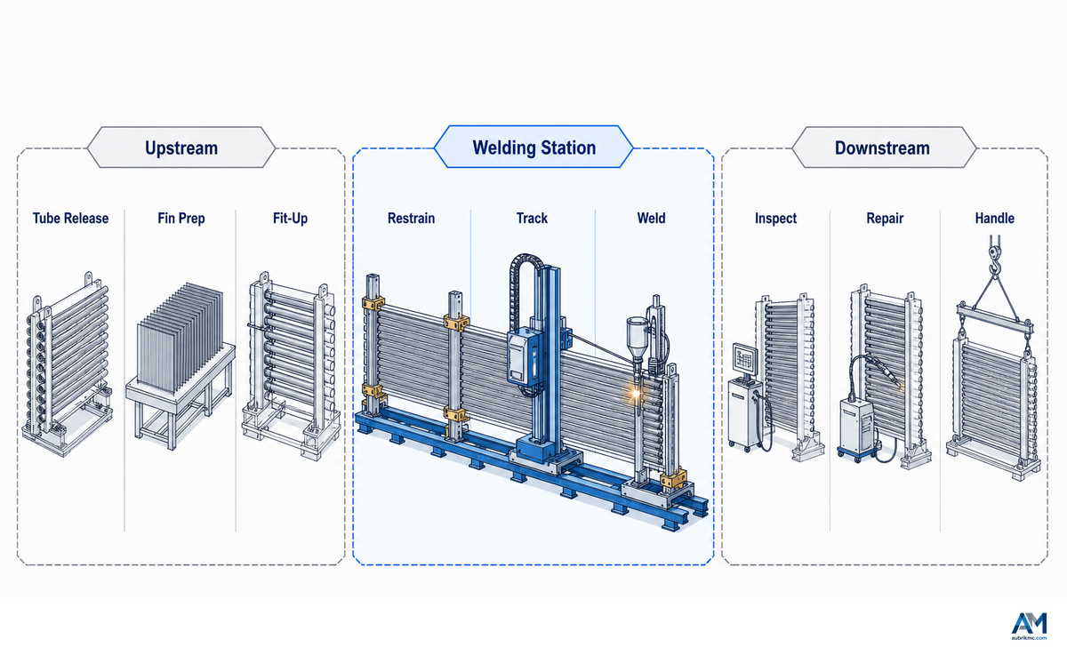
Flujo de preparación del panel en 7 etapas: desde los tubos y las barras de aleta hasta la inspección final
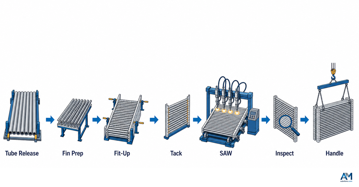
Para construir paredes de membrana de calderas, utilice la siguiente secuencia como marco de planificación y no como hoja de ruta universal. Los puntos de espera reales dependen del plano, el material, el procedimiento de soldadura, el plan de inspección y la distribución de la planta. Su propósito es mostrar qué debe liberarse antes de que la siguiente etapa procese el trabajo.
- Durante la liberación de los materiales, coteje los tubos, las barras de aleta, el sistema de material de aporte/fundente y los documentos sujetos a control de revisiones. Que un insumo tenga una apariencia similar no demuestra que sea equivalente.
- Durante la preparación, confirme las características que afectan el armado y ajuste y el comportamiento del arco, como la rectitud, la geometría de las aletas, el estado del corte y la condición especificada de preparación de la superficie. Registre las dimensiones en mm o en la unidad exigida por el plano, en lugar de convertirlas informalmente en la estación.
- Para la carga y el armado y ajuste, ubique las piezas, verifique la alineación y el estado de la junta y, después, registre la liberación. No use la máquina como un calibrador motorizado para forzar insumos no conformes hasta colocarlos en su sitio.
- Durante la soldadura controlada, seleccione la configuración autorizada, confirme los consumibles y la conexión de retorno y supervise las variables exigidas por el procedimiento o el plan de control.
- Durante la limpieza y la preparación del acceso, retire el material que oculte la soldadura o interfiera con la siguiente pasada, inspección o etapa de manejo.
- Para la inspección y disposición, evalúe el estado de las soldaduras y las dimensiones del panel mediante el método definido para el proyecto. Registre la aceptación, la ruta de reparación o la revisión de ingeniería.
- Durante la descarga y transferencia al proceso posterior, proteja el panel contra daños de manejo o deformaciones no controladas y mantenga la trazabilidad asociada con la pieza de trabajo.
ISO 13920:2023 proporciona clases generales de tolerancia para construcciones soldadas, pero su registro público también establece que los planos y los requisitos funcionales son fundamentales para determinar las tolerancias aplicables. En un panel de membrana, esto significa que la verificación de liberación debe citar el plano y los documentos de aceptación del comprador, en lugar de una tolerancia copiada de un panel no relacionado.
Para mantener la trazabilidad, registre la procedencia de fabricación de los tubos y el diámetro real cuando la especificación del material o el plan del comprador así lo exijan. En los documentos de compras, el mismo conjunto controlado puede denominarse panel de pared de membrana.
El diagrama del flujo de trabajo de los equipos de producción de calderas es una referencia útil porque la soldadura de paneles suele tener interdependencias con la preparación de la producción previa y la fabricación posterior. El diagrama supone que un mismo taller solo utilizará algunas de las estaciones de equipos indicadas.
Mapa de restricciones de la línea de paneles con 7 puntos de control: encuentre el verdadero cuello de botella
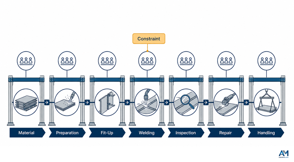
El rendimiento útil está determinado por el punto de control repetible más lento que libera trabajo aceptable con la combinación de productos prevista. Un ciclo de soldadura rápido puede coexistir con una línea lenta si las esperas por el armado y ajuste, las interrupciones de los consumibles, las colas de inspección, las reparaciones o la descarga detienen con frecuencia el siguiente panel.
| Punto de control/observación | Posible restricción | Medición | Pregunta correctiva del responsable |
|---|---|---|---|
| 1. Cola de liberación de materiales | Discrepancia de trazabilidad o documentación | Tiempo de espera y lotes rechazados por motivo | ¿Qué registro falta para poder iniciar la preparación? |
| 2. Finalización de la preparación | Acumulación de tubos/aletas pendientes por su estado o limpieza | Conjuntos preparados por turno y liberación al primer intento | ¿Qué característica de los insumos provoca más retenciones? |
| 3. Liberación del armado y ajuste | Alineación, estado de la junta o carga del dispositivo de sujeción | Tiempo desde la carga hasta la liberación y cantidad de ajustes | ¿El retraso se debe a la geometría de los insumos, al método o al acceso? |
| 4. Ciclo activo de soldadura | Recorrido, inicios/paradas o interrupción del movimiento | Tiempo con el arco encendido, tiempo sin arco y motivo de la parada | ¿Qué parada controla la estación? |
| 4. Continuidad de los consumibles | Suministro, acondicionamiento o reabastecimiento de alambre de soldadura/fundente | Interrupciones y tiempo transcurrido de recarga/recuperación | ¿Puede realizarse el reabastecimiento sin interrumpir la secuencia de liberación? |
| 5. Liberación de inspección | Enfriamiento, acceso, verificación dimensional o cola del inspector | Tiempo desde la finalización del ciclo hasta la disposición | ¿Qué evidencia puede prepararse durante el ciclo y no después? |
| 6. Reparación/disposición | Defecto recurrente o decisión de ingeniería lenta | Eficiencia de producción, aceptación al primer intento y horas de retrabajo por causa | ¿El problema está en los materiales, el armado y ajuste, el proceso, el movimiento o la inspección? |
| 7. Manejo/descarga | Grúa, rodillo, espacio en el piso o bloqueo del proceso posterior | Tiempo desde la liberación hasta el despeje y eventos de ciclo bloqueado | ¿Puede entrar el siguiente panel mientras se transfiere el anterior? |
| Cambio de producto entre puntos de control | Variación de la combinación de productos y verificación de la configuración | Tiempo desde la última pieza aceptable hasta la primera pieza aceptable por familia de productos | ¿Qué ajustes, dispositivos de sujeción y verificaciones cambian realmente? |
Ejemplo práctico sin inventar resultados de producción: suponga que, en la mayoría de los ciclos, el carro de soldadura termina antes de que se libere el armado y ajuste, mientras que la inspección y la descarga permanecen despejadas. Aumentar la velocidad de recorrido generaría más espera en la estación de soldadura, no más paneles liberados. Vuelva a medir los siete puntos de control después de un experimento que reduzca la variación del armado y ajuste o el tiempo de liberación. Esta lógica identifica dónde realizar las pruebas; no predice un aumento porcentual.
Normalice todas las comparaciones de productividad. «Paneles por día» es un dato incompleto si no se definen también la longitud y el ancho del panel, la geometría de tubos/aletas, la secuencia de soldadura, la calidad aceptada, la duración del turno, la combinación de cambios de producto y el tratamiento del retrabajo. Aplique la misma precaución a la cantidad de antorchas y a la velocidad de recorrido anunciada.
Escenario ilustrativo solo para fines de normalización: si dos propuestas indican una disponibilidad de 90% y 95%, pero una excluye un periodo planificado de cambio de producto de 10%, esas cifras no son comparables. Sustituya estos porcentajes de ejemplo por datos específicos del sitio; no son afirmaciones de desempeño de Aubrik ni objetivos de aceptación.
Cuando la liberación dimensional forme parte de un punto de control, utilice el plano del comprador y el marco de tolerancias generales ISO 13920:2023 aplicable únicamente cuando los documentos rectores realmente lo invoquen.
Establezca una ventana de proceso sin tratar los ajustes de la máquina como una WPS
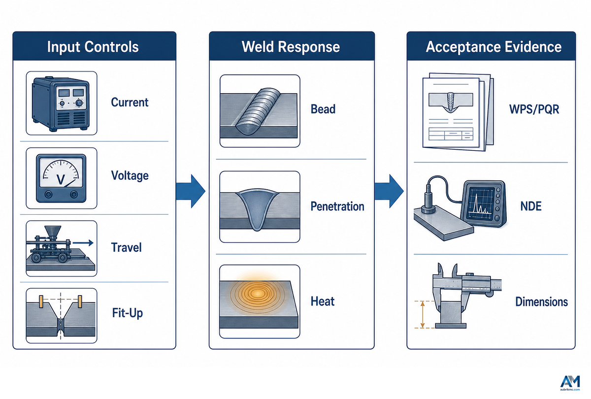
Una ventana de proceso vincula las variables ajustables con un resultado aprobado y define cómo gestionar las desviaciones. El posicionamiento preciso de la antorcha puede contribuir a obtener una soldadura uniforme, pero ninguna de esas expresiones constituye un resultado de aceptación hasta que se aprueben los exámenes y las verificaciones dimensionales especificados. Los proveedores de equipos explican los controles disponibles; la organización responsable de la soldadura califica y aprueba el procedimiento aplicable; el contrato identifica la evidencia de aceptación.
Un estudio de acceso abierto de 2024 sobre acero P355N utilizado en recipientes a presión varió la corriente de soldadura por arco sumergido de 300 A a 700 A dentro de su propia configuración experimental y registró cambios en la penetración, el comportamiento a la tracción, la dureza y la microestructura. Estos resultados muestran por qué las variables deben evaluarse en conjunto. No establecen un rango de ajustes para la producción de uniones entre tubos y aletas.
Ejemplo de límites específicos del estudio: en ese experimento con P355N, se produjo penetración incompleta a 300 A y 400 A; la Tabla 1 registró un esfuerzo máximo de 496.29 MPa a 500 A y una deformación de 18.67% a 600 A, dentro del rango experimental de 300 A a 700 A del artículo. Estos resultados no pueden transferirse a la producción de paneles. Demuestran por qué una ventana de procedimiento debe verificarse con la junta, el material y la base de aceptación reales.
Otro estudio de 2024 revisado por pares sobre placas de acero ASTM A516 Grado 70 evaluó como un sistema acoplado la corriente, el voltaje, la velocidad de recorrido, el flujo de calor, la geometría de la zona afectada por el calor, la microestructura y la dureza. La lección transferible es el método: vincular los parámetros de entrada con resultados verificados, no aplicar la receta numérica del estudio.
| Variable o condición | Por qué está vinculada | Evidencia que debe registrarse | Límite de aprobación |
|---|---|---|---|
| 1. Corriente | Interactúa con el alambre de soldadura, el recorrido, el aporte térmico, el perfil de fusión y la deposición. | Valor de ajuste y tendencia real, cuando estén disponibles | WPS aplicable y control de ingeniería |
| 2. Voltaje | Modifica el comportamiento del arco y debe evaluarse junto con la corriente y la geometría. | Rango autorizado y desviaciones registradas | Procedimiento aplicable |
| 3. Velocidad de recorrido | Afecta el tiempo por unidad de longitud y la distribución del calor; una mayor velocidad no es automáticamente aceptable. | Movimiento ordenado y real, más el resultado de la soldadura | Procedimiento y resultado de aceptación |
| 4. Sistema de alambre de soldadura y fundente | La selección y el estado de los consumibles afectan el comportamiento del arco y del depósito. | Clasificación, fabricante, lote y registro del estado | Procedimiento y control de compras |
| 5. Posición del electrodo/extensión libre | La ubicación del cabezal, el estado del contacto y la distancia de trabajo afectan la estabilidad. | Verificación de la configuración y revisión de mantenimiento | Hoja de procedimiento/configuración |
| 6. Armado y ajuste de la junta | La separación, la alineación, el contacto y la sujeción modifican la junta que se presenta al arco. | Liberación previa a la soldadura y registro de excepciones | Plano y criterios de armado y ajuste |
| 7. Superficie y conexión de retorno | La contaminación o una trayectoria de retorno inestable pueden distorsionar los resultados de una prueba de ajustes. | Liberación de la preparación y verificación de la conexión | Instrucción de trabajo |
| 8. Controles de secuencia/entre pasadas | Las múltiples soldaduras y el historial térmico pueden afectar la geometría y el trabajo posterior. | Secuencia de pasadas, tiempos y evidencia de la temperatura especificada | Procedimiento aplicable |
| 9. Resultado verificado | Un ajuste solo es útil cuando se aprueban los resultados exigidos de soldadura y dimensiones. | Resultados de inspección vinculados con los parámetros registrados | Disposición de aseguramiento de la calidad y aceptación contractual |
La velocidad de recorrido o las altas tasas de deposición no deben considerarse mejoras independientes: el tamaño y la calidad exigidos de la soldadura aún deben aprobarse, mientras que la composición de los consumibles modifica el comportamiento de la deposición y la penetración.
Condición de parada: si el equipo no puede identificar el plano rector, la revisión del procedimiento, la base de consumibles y el método de aceptación, no «ajuste hasta que se vea bien». Resuelva primero la falta de documentación y la asignación de responsabilidades.
Matriz de defectos y controles con 10 causas
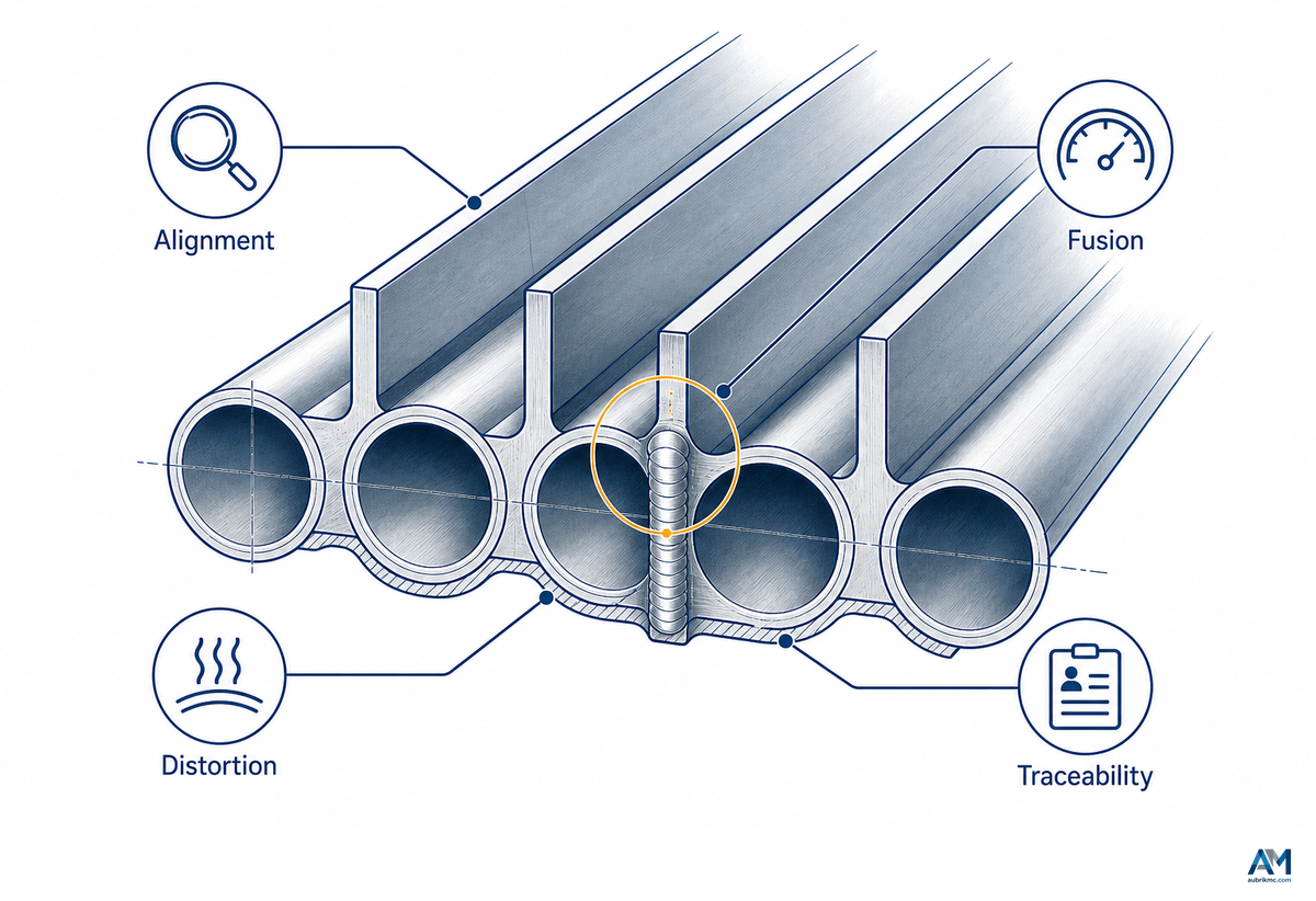
En la producción de paneles de paredes de agua para calderas, un síntoma visible en una soldadura o un panel rara vez demuestra una sola causa raíz. Comience la revisión separando tres grupos de evidencia: materiales y armado y ajuste, proceso y equipos de soldadura, y resultados dimensionales o de inspección posteriores a la soldadura. Cambie un solo factor controlado únicamente después de conservar la evidencia existente.
¿Cómo pueden minimizarse los defectos de soldadura en paneles de tubos para calderas?
Libere insumos uniformes, ejecute el procedimiento aplicable, registre las variables críticas, inspeccione en los puntos de espera definidos y clasifique las no conformidades recurrentes mediante evidencia, no solo por su apariencia. La prevención mejora cuando los registros de preparación, armado y ajuste, estado de los consumibles, movimiento, inspección y reparación pueden vincularse con el mismo panel.
| Observación | Posibles factores que deben investigarse | Primera verificación de evidencia | Registro que debe conservarse/límite de escalamiento |
|---|---|---|---|
| 1. Indicación de falta de fusión | Presentación de la junta, posición, distribución del calor, recorrido y compatibilidad entre consumible y proceso | Liberación del armado y ajuste, más el registro de los parámetros reales y la posición del cabezal | Resultado de la inspección; ingeniería de soldadura establece la acción correctiva |
| 2. Indicación de porosidad | Estado de la superficie, estado de los consumibles, cobertura/manejo del fundente e interrupción del proceso | Evidencia de la preparación de los materiales y del lote/estado de los consumibles | Mapa de indicaciones; la disposición sigue la ruta de aceptación especificada |
| 3. Socavado | Interacción entre posición, corriente/voltaje/recorrido y geometría de la junta | Compare los ajustes y la configuración reales con la base aprobada | Ubicación y extensión; no prescriba una reparación a partir de esta tabla |
| 4. Penetración incompleta | Armado y ajuste, forma de la junta, interacción entre corriente y recorrido, y posición de trabajo | Medición precisa de la junta y trazabilidad del proceso para la longitud afectada | Evidencia de inspección de la calidad de la soldadura y revisión de ingeniería |
| 5. Penetración excesiva o perforación por quemado | Geometría de los insumos, separación local, interacción entre energía y recorrido, y selección del electrodo | Compare el armado y ajuste local con las condiciones registradas del proceso | Ubicación exacta, lote de insumos y revisión del procedimiento |
| 6. Cordón irregular o inestabilidad del arco | Alimentación de alambre, estado del contacto, conexión de retorno, perfil de los puntos de soldadura, trayectoria del fundente e interrupción del movimiento | Historial de alarmas/paradas, trayectoria de alimentación, conexión e inspección de la configuración | Conserve la cronología del evento antes de restablecer el equipo |
| 7. Desalineación entre tubos y aletas | Geometría de los insumos, desgaste de los posicionadores, método de carga, sujeción y movimiento térmico | Registro dimensional previo y posterior a la soldadura | Característica del plano y método de medición utilizado |
| 8. Distorsión del panel | Curvatura o rectitud de los insumos, sujeción, secuencia, distribución del calor y manejo antes de la liberación | Geometría etapa por etapa, no solo la medición final | Momento de la medición y condición de apoyo |
| 9. Problema con el manejo de la escoria o el fundente | Estado del fundente, trayectoria de recuperación, cobertura, acceso para limpieza e interrupción | Manejo de consumibles e inspección de recuperación/limpieza | Lote, estado y longitud afectada; siga las reglas del procedimiento |
| 10. Retrabajo recurrente | Familia de insumos sin control, error de cambio de producto, ciclo de retroalimentación deficiente y disposición repetida | Análisis de Pareto por familia de productos, punto de control, turno y causa verificada | Registro de acciones correctivas; la dirección es responsable del cierre sistémico |
Esta matriz se detiene deliberadamente antes de proporcionar instrucciones de reparación. Los métodos de aceptación y las rutas de reparación varían según el contrato, el código, el material, la junta y el procedimiento calificado. Una tabla de diagnóstico puede organizar la evidencia; no puede autorizar una reparación en producción.
Si el plan de inspección exige un examen ultrasónico, registre el método, la cobertura, la base de aceptación y la identidad del panel; la máquina no determina por sí misma la disposición.
Dónde termina el alcance de la estación de soldadura de paneles: tareas que requieren otra etapa del proceso
En la soldadura de paneles de tubos, una línea de unión larga y repetitiva entre tubos y aletas representa un problema de producción distinto al de una junta de extremo de tubo, una reparación local, un elemento adosado, un recubrimiento o una soldadura corta con obstrucciones. Defina el límite a partir del acceso a la junta, la geometría, la base aplicable para la calificación del procedimiento, los requisitos de calidad y el manejo, no por el deseo de que una sola máquina realice todas las soldaduras.
| Tarea | Por qué puede quedar fuera de la estación de paneles | Siguiente pregunta |
|---|---|---|
| Conexión de extremo de tubo o cabezal | Geometría, acceso, posición y ruta de inspección diferentes para la junta | ¿Qué proceso calificado y dispositivo de sujeción cubren esta junta? |
| Reparación de defectos locales | Requiere una disposición autorizada y acceso controlado a una ubicación específica | ¿Qué procedimiento de reparación y reinspección están aprobados? |
| Líneas de unión cortas o interrumpidas | Los inicios, las paradas y las obstrucciones pueden tener más peso que el recorrido continuo | ¿Una estación automatizada o manual diferente controlaría mejor la junta? |
| Recargue o revestimiento | La función del depósito y la base del procedimiento difieren de las correspondientes a la unión entre tubos y aletas | ¿Qué material, dilución, espesor y examen se aplican? |
| Elementos adosados y orejas | La sujeción local, el acceso y la trayectoria térmica difieren de los de la línea de unión principal | ¿En qué punto de la ruta deben agregarse? |
| Geometría curva no estándar | La trayectoria de la pieza de trabajo y la sujeción pueden exceder el rango de diseño de la línea | ¿Pueden validarse el dispositivo de sujeción y el movimiento para la forma real? |
Esta sección no clasifica la soldadura SAW, MIG/MAG, la soldadura robotizada ni los métodos manuales por precio o desempeño anunciado. Estas son decisiones de configuración vinculadas con el rango real de productos. El pulido, el revestimiento y el trabajo en los extremos de los tubos efectuados posteriormente también necesitan su propia ruta. Para tomar decisiones sobre alcances adyacentes, consulte la máquina dobladora de paneles de Aubrik para la geometría posterior a la fabricación del panel y su máquina de soldadura de tubo a tubo para definir la ruta de las juntas de extremos. El equipo de compras debe identificar primero qué familias de juntas debe cubrir la estación de paneles y cuáles corresponden a otras estaciones.
Integración y servicios auxiliares: los requisitos que los compradores descubren demasiado tarde
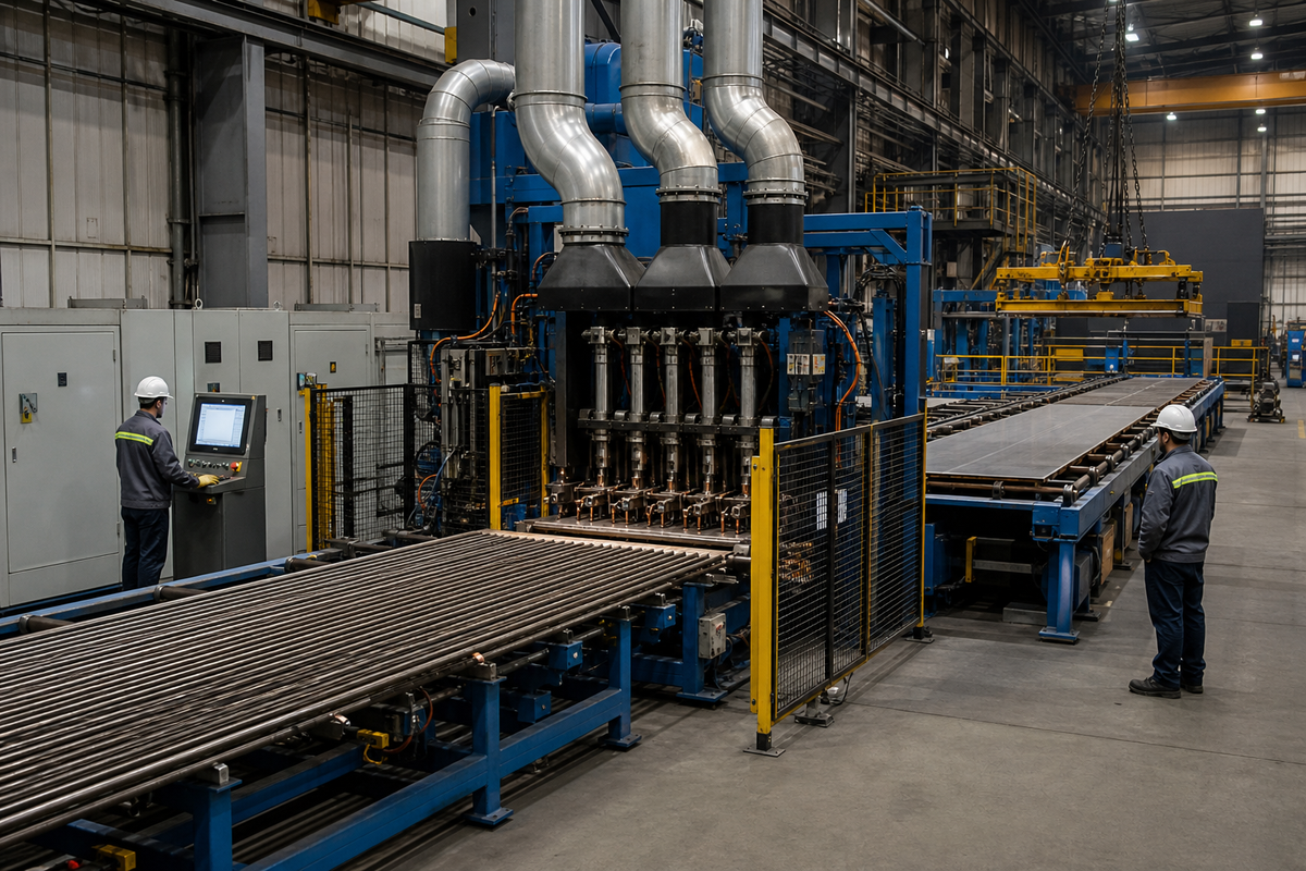
La aceptación del equipo suele centrarse en la máquina energizada, mientras la interfaz de producción sigue sin definirse. Una línea horizontal puede superar un ciclo en seco aislado y aun así no cumplir con el flujo previsto porque la pieza de trabajo no puede llegar, no se pueden reponer los consumibles, no se recopilan evidencias o el panel terminado no puede salir.
Para los centros de trabajo de Estados Unidos, OSHA 1910.252 exige que las operaciones de soldadura aborden los riesgos de incendio y cuenten con ventilación adecuada para los humos, gases, polvos y condiciones del lugar de trabajo. Esto respalda la inclusión explícita de los sistemas de extracción y control de incendios como elementos de la interfaz. No establece un caudal de aire universal ni sustituye la revisión de la normativa local y de higiene industrial.
- Defina el rango de productos: diámetro de los tubos y rango de aletas, ancho y longitud del panel, masa, familia de juntas y frecuencia de la mezcla de productos.
- Trace el flujo de materiales: dirección de recepción, área de preparación, carga, descarga, puntos de izaje y destino posterior.
- Verifique la cimentación y el acceso: carga sobre el piso, alineación, anclaje, espacio para mantenimiento, ruta del operador y zonas protegidas.
- Documente la interfaz eléctrica: características del suministro, distribución, dispositivos de protección, puesta a tierra y responsabilidad de la conexión.
- Asigne los controles de humos e incendios: concepto de extracción, aire de reposición, controles para trabajos en caliente, gestión de combustibles y revisión de la jurisdicción competente.
- Planifique el sistema de consumibles: almacenamiento del alambre de soldadura y fundente, acondicionamiento cuando sea necesario, alimentación, recuperación, limpieza y trazabilidad de lotes.
- Especifique los controles y datos: recetas, niveles de acceso, alarmas, enclavamientos, E/S, registros de producción, respaldos y perímetro de ciberseguridad.
- Enumere los servicios auxiliares: aire comprimido, enfriamiento, extracción u otros servicios, solo cuando los requiera la configuración seleccionada.
- Planifique el soporte de mantenimiento: aislamiento seguro, acceso a piezas de desgaste, instrumentos que deben calibrarse o verificarse, asistencia para diagnóstico y estrategia de refacciones.
- Defina la entrega al proceso siguiente: criterios de enfriamiento o sujeción, posición para la verificación dimensional, marcado, trazabilidad, soporte de almacenamiento y siguiente operación.
Asigne cada interfaz al comprador, al proveedor o a un tercero antes de realizar el pedido. “Por terceros” no identifica a un responsable. Para cada elemento, indique quién proporciona los datos, quién diseña la interfaz, quién la instala y qué evidencia confirma su cierre.
Matriz de aceptación de RFQ de 12 entradas para paneles de membrana

Una RFQ lista para tomar decisiones comienza con evidencias de producción, no con una cantidad solicitada de antorchas de soldadura. Las 12 entradas siguientes permiten que el proveedor explique una configuración adecuada, a la vez que el comprador conserva la responsabilidad sobre los requisitos del producto, la base del procedimiento y los criterios de aceptación.
Incluya referencias como ASME BPVC Section IX e ISO 13920:2023 en la RFQ solo cuando el código de construcción aplicable, el plano, el contrato y el plan de aceptación determinen que son pertinentes.
Convierta los rangos publicados en evidencias de aceptación:
A julio de 2026, la página de configuraciones comerciales de Aubrik publica un rango específico del proveedor con una velocidad de soldadura de 0.8 m/min a 2.0 m/min, seguimiento de junta de ±0.5 mm, espesor de panel de 3 mm a 16 mm, diámetro exterior de tubo de 22 mm a 108 mm, ancho estándar de panel de 1,600 mm con un ancho personalizado de hasta 2,500 mm y diámetro de alambre de soldadura de 2.4 mm o 3.2 mm. Estas cifras describen la configuración publicada de Aubrik, no límites universales del proceso ni resultados garantizados.
Para una prueba de límites específica del proveedor, la RFQ puede solicitar evidencias en los casos inferiores y superiores aplicables: espesores de 3 mm y 16 mm, diámetros exteriores de tubo de 22 mm y 108 mm, anchos de 1,600 mm y 2,500 mm, alambres de soldadura de 2.4 mm y 3.2 mm, además de velocidades registradas dentro del rango de 0.8 m/min a 2.0 m/min. Utilice únicamente los casos permitidos por el plano del comprador, la base del procedimiento y el alcance acordado de la FAT.
| Entrada | El comprador proporciona | El proveedor confirma | La FAT demuestra | Registro de entrega |
|---|---|---|---|---|
| 1. Mezcla de productos | Familias de paneles representativas y frecuencia prevista | Familias incluidas y método de cambio de producto | Pruebas representativas acordadas | Matriz de configuraciones y productos |
| 2. Materiales de tubos y aletas | Especificaciones, grados y necesidades de trazabilidad | Supuestos de compatibilidad y exclusiones | Material de prueba correcto e identificado | Registros de materiales y consumibles |
| 3. Rango de tamaños | Dimensiones de tubos, aletas y juntas con su revisión | Rango operativo y herramental requerido | Casos límite seleccionados | Rango aprobado y lista de herramental |
| 4. Rango dimensional del panel | Datos de ancho, longitud, masa, soporte e izaje | Solución de carga, sujeción, recorrido y descarga | Movimiento seguro de los paneles acordados | Instrucciones de distribución y manipulación |
| 5. Geometría de la junta | Planos, criterios de armado y ajuste, y requisitos de punteo y secuencia | Criterios del dispositivo de sujeción y acceso del cabezal | Preparación repetible y juntas terminadas | Hojas de preparación y planos |
| 6. Definición de la producción | Duración del turno, mezcla de productos, pausas planificadas y tratamiento de la inspección y el retrabajo | Supuestos del ciclo y tiempo excluido | Tiempos medidos por etapa y unidades aceptadas | Registro de prueba firmado con los supuestos |
| 7. Base del procedimiento | Responsabilidad sobre las WPS/PQR aplicables y plan de calificación | Controles disponibles y captura de datos | Ejecución conforme a la base autorizada de la prueba | Registros de preparación vinculados a la revisión |
| 8. Consumibles | Clasificaciones aprobadas y reglas de almacenamiento y trazabilidad | Interfaces de alimentación y recuperación, y supuestos de capacidad | Suministro estable durante la prueba acordada | Ruta de consumibles y registro de mantenimiento |
| 9. Criterios dimensionales | Características del plano, tolerancias, condición de soporte y precisión de medición | Contribución y límites del dispositivo de sujeción y del control | Dimensiones registradas antes y después de la soldadura | Formatos de inspección y método de medición |
| 10. Criterios de soldadura e inspección | Método de examen, muestreo, aceptación y ruta de disposición | Acceso y soporte para los datos del proceso | Inspección acordada del resultado de la prueba | Informes vinculados a la identificación del panel |
| 11. Servicios y controles | Servicios disponibles, reglas de la planta, interfaces y política de datos | Cargas, puntos de conexión, E/S, enclavamientos y exclusiones | Verificaciones funcionales y de la interfaz de seguridad dentro del alcance acordado | Planos conforme a obra, respaldos y ajustes |
| 12. Paquete de soporte | Idioma, público de la capacitación y expectativas de respuesta y refacciones | Manuales, capacitación, garantía, refacciones y alcance del soporte | Revisión de documentos y ejercicios de operación y mantenimiento | Expediente aceptado y lista de asuntos pendientes |
¿Qué datos de producción debe preparar un comprador antes de aceptar una línea de soldadura de paneles de membrana?
Prepare la matriz de familias de productos, los materiales y planos reales, las reglas de juntas y armado y ajuste, la responsabilidad del procedimiento, los consumibles, los criterios dimensionales y de aceptación de soldaduras, los supuestos del turno, los servicios, las interfaces de control, la capacitación, las refacciones y los documentos de entrega. Después, seleccione pruebas FAT que representen casos límite difíciles y la familia de producción habitual, no solo un cupón de demostración conveniente.
Regla mínima viable para la RFQ
Si una promesa de producción no puede vincularse con un producto definido, una soldadura y geometría aceptadas, un modelo de turnos, una ruta de inspección y un tratamiento del retrabajo, todavía no constituye un compromiso de producción comparable. Pida al proveedor que indique cada supuesto junto al resultado.
Una vez definidas las 12 entradas, revise las configuraciones de máquinas de soldadura para paneles de membrana de Aubrik. Esa página comercial es el lugar correcto para consultar opciones de equipos, especificaciones propias del proveedor, personalización y cuestiones de cotización; esta guía sigue siendo la referencia sobre el proceso y la aceptación.
Preguntas frecuentes
Para conocer el alcance de la calificación y las tolerancias en las respuestas siguientes, consulte los documentos aplicables del proyecto junto con ASME BPVC Section IX e ISO 13920:2023. Estos documentos públicos son referencias de alcance, no criterios de aceptación del proyecto.
¿Qué son los paneles de membrana en tubos de caldera y por qué son importantes?
Los paneles de membrana son conjuntos en los que los tubos se unen mediante aletas o barras para formar una sección de pared continua. Su diseño y función exactos proceden del paquete de ingeniería de la caldera. Desde el punto de vista de la fabricación, la geometría unida integra la condición de los tubos, la preparación de las aletas, el armado y ajuste, la integridad de las soldaduras, las dimensiones del panel y la trazabilidad en una sola ruta de producción controlada. Esta función de pared compartida hace que la liberación dimensional y la trazabilidad sean tan importantes como la apariencia del cordón durante el posterior montaje de la caldera, la documentación de las partes sometidas a presión y la inspección final.
¿Qué proceso de soldadura se utiliza para los paneles de membrana de calderas?
Los procesos de soldadura por arco sumergido y con gas de protección pueden utilizarse en los sistemas de producción de paneles, según el diseño de la junta, el material, el acceso, el procedimiento y la configuración del equipo. El nombre del proceso por sí solo no determina la selección de la máquina. Los compradores deben proporcionar el rango de productos y la base de calificación, y después verificar que el proceso y los controles propuestos puedan generar las evidencias especificadas.
¿Cómo afecta la automatización a la uniformidad de las soldaduras de paneles de membrana?
La automatización puede repetir el movimiento coordinado, la alimentación de alambre, el recorrido y las configuraciones almacenadas con mayor uniformidad que una secuencia manual sin control. No puede garantizar resultados uniformes cuando varían la geometría de entrada, la condición de la superficie, el armado y ajuste, los consumibles o las reglas de inspección. La automatización ofrece sus mejores resultados cuando los criterios de liberación previos y las evidencias posteriores se controlan con el mismo rigor. La uniformidad debe evaluarse con entradas liberadas y resultados aceptados, utilizando la misma familia de productos, revisión del procedimiento, método de inspección y condición de soporte en cada prueba; conserve el resultado en los registros de revisión de producción.
¿Cuáles son las verificaciones clave del control de calidad para la soldadura de paneles de membrana?
Verifique la identificación del material, la geometría de los tubos y las aletas, la condición de la superficie, el armado y ajuste, la configuración autorizada del proceso, la trazabilidad de los consumibles, las variables registradas, el examen de las soldaduras, las dimensiones posteriores a la soldadura y la disposición final. Vincule cada resultado con el panel, la revisión del plano, la base del procedimiento, el método de medición y el revisor responsable para poder rastrear y resolver cualquier excepción.
¿Qué debe registrarse durante una FAT de paneles de membrana?
Registre el producto y el material exactos de la prueba, las revisiones del plano y el procedimiento, la configuración y los consumibles, el estado de los servicios y el software, las verificaciones funcionales o de seguridad, los tiempos de cada etapa, las interrupciones, las evidencias reales del proceso, las dimensiones antes y después de la soldadura, los resultados de inspección, el retrabajo o los asuntos pendientes y los supuestos en los que se basa cualquier resultado de producción. Incluya la ruta de carga y descarga, el acceso para mantenimiento, el historial de alarmas y paros, las acciones del operador, la condición de soporte para la medición, así como el responsable y la fecha límite de cada hallazgo sin resolver antes de cerrar la prueba o programar una repetición.
Conserve tanto el registro de tiempos sin procesar como el resumen. Vincule cada resultado de inspección con el panel de prueba y sus ajustes, identifique al responsable de cada acción pendiente e indique si es necesario repetir la prueba. Conserve una aceptación firmada en lugar de depender de un video o de una frase de aprobado/reprobado.
¿Cuándo una máquina de soldadura para paneles de membrana no es la herramienta adecuada?
Una máquina de soldadura para paneles de membrana puede no ser la estación adecuada cuando el trabajo consiste en una junta de extremo de tubo, una reparación localizada, un elemento adosado, un recargue, una línea de unión corta y obstruida o una geometría fuera del rango previsto del dispositivo de sujeción y del movimiento. Canalice esas juntas mediante una decisión de ingeniería y de procedimiento independiente. No las fuerce a pasar por la línea de paneles solo porque requieren soldadura.
Convierta la selección de la máquina en una decisión de producción controlada

Una secuencia confiable es fácil de expresar y exigente de ejecutar: libere las entradas, arme y sujete el trabajo, ejecute el procedimiento calificado aplicable, conserve las evidencias del proceso, inspeccione la soldadura y el panel, resuelva las excepciones y despeje la ruta hacia el proceso siguiente. Cuatro recursos de trabajo —el flujo de 7 etapas, el mapa de restricciones de 7 puntos de control, la matriz de diagnóstico de 10 causas y la matriz de RFQ de 12 entradas— asignan un responsable visible a cada decisión.
La capacidad de la máquina sigue siendo importante. Solo adquiere sentido después de que el comprador define qué debe fabricar la línea y cómo se demostrará que el resultado es aceptable. Mantenga el trabajo de configuración y cotización en la página de la solución comercial, y conserve esta guía como la lógica operativa que comparten producción, ingeniería de soldadura, calidad, mantenimiento y compras.
Referencias y fuentes
- ASME, BPVC Section IX: Calificaciones de soldadura, soldadura fuerte y fusión (registro de la edición 2025)
- ISO, ISO 13920:2023, Tolerancias generales para construcciones soldadas
- Materials (2024) — Influencia de la intensidad de corriente de soldadura por arco sumergido en el acero P355N
- The International Journal of Advanced Manufacturing Technology (2024) — Proceso SAW y observaciones metalúrgicas
- OSHA, 29 CFR 1910.252, Requisitos generales de soldadura
- The Fabricator, Uso de alambre tubular en aplicaciones de soldadura por arco sumergido
- Canadian Metalworking, Fundamentos de la soldadura por arco sumergido
Tendencia ahora