Entre em contato com a Aubrik Company

Guia da máquina de soldagem de painéis membrana para controle de processo e qualidade

Guia de produção de painéis de caldeira
Atualizado em julho de 2026
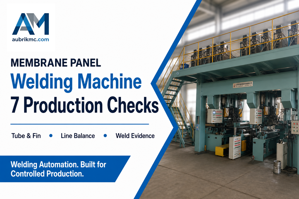
Uma máquina de soldagem de painéis membrana é a estação de união de um sistema maior de produção de tubos e barras de membrana. Ela pode coordenar o movimento de soldagem e garantir a repetibilidade dos parâmetros do processo, mas não consegue corrigir materiais não verificados, ajuste e montagem inadequados da junta, um procedimento impróprio, inspeções tardias ou o bloqueio da descarga. Portanto, para componentes estruturais de caldeiras, a produção de painéis de boa qualidade deve ser planejada desde a liberação dos materiais até a transferência final, e não apenas com base na quantidade de tochas ou na velocidade de soldagem.
Resposta rápida: defina os limites dimensionais e técnicos do produto, libere o ajuste e a montagem dos tubos e das barras de membrana, trabalhe conforme o procedimento de soldagem qualificado aplicável, inspecione tanto a solda quanto a geometria do painel e teste todo o fluxo de produção durante a aceitação. A capacidade útil da linha é determinada pela etapa repetível mais lenta diante da combinação real de produtos.
Na prática, a máquina de soldagem de painéis fica entre a preparação e a inspeção em uma linha de produção mais ampla; as juntas de extremidade entre tubos ou dutos podem ser encaminhadas a outra estação.
1. Separe as três camadas de controle.
As configurações da máquina, a qualificação do procedimento e a aceitação contratual estão relacionadas, mas não são intercambiáveis.
As configurações da máquina, a qualificação do procedimento e a aceitação contratual estão relacionadas, mas não são intercambiáveis.
2. Meça as sete etapas da produção.
Preparação, ajuste e montagem da junta, consumíveis, inspeção, reparo e movimentação de peças podem limitar a produção antes mesmo do curso de soldagem.
Preparação, ajuste e montagem da junta, consumíveis, inspeção, reparo e movimentação de peças podem limitar a produção antes mesmo do curso de soldagem.
3. Faça o diagnóstico com base em evidências.
Analise os materiais e o ajuste e a montagem da junta, os registros do processo e as dimensões após a soldagem antes de alterar uma configuração.
Analise os materiais e o ajuste e a montagem da junta, os registros do processo e as dimensões após a soldagem antes de alterar uma configuração.
4. Compre resultados comprovados, não apenas uma especificação de destaque.
A solicitação de cotação (RFQ) e o teste de aceitação em fábrica (FAT) devem padronizar a combinação de produtos, as premissas dos turnos, os critérios de inspeção e os registros de entrega.
A solicitação de cotação (RFQ) e o teste de aceitação em fábrica (FAT) devem padronizar a combinação de produtos, as premissas dos turnos, os critérios de inspeção e os registros de entrega.
O que uma máquina de soldagem de painéis membrana controla e o que ela não controla
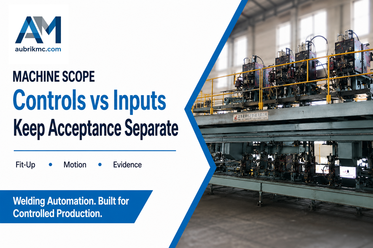
Um conjunto preparado de tubos e barras de membrana é movimentado, imobilizado, energizado e soldado dentro da faixa prevista no projeto da estação. Os controles de produção ao redor determinam se esse conjunto estava apto para soldagem e se o painel acabado é aceitável. Tratar ambos como uma única responsabilidade da máquina oculta a origem das variações.
O registro público da ASME para a edição de 2025 da Seção IX do BPVC descreve as regras de qualificação de procedimentos e profissionais de soldagem exigidas por outras seções do BPVC. Ele não fornece uma receita de configuração para painéis membrana. Essa distinção é importante: o equipamento pode reproduzir parâmetros aprovados, enquanto a especificação de procedimento de soldagem (WPS), o registro de qualificação do procedimento (PQR) e os documentos contratuais aplicáveis definem a base qualificada e aceita.
| Item | Relação com a estação | Responsável principal | Liberação ou comprovação |
|---|---|---|---|
| 1. Identificação dos materiais | Tubos, barras de membrana, arame de soldagem e fluxo liberados entram na máquina; a estação não estabelece a rastreabilidade. | Materiais e garantia da qualidade | Registros de corrida/lote e identificação dos consumíveis |
| 2. Geometria dos tubos e das barras de membrana | Os dispositivos de fixação só conseguem posicionar peças cuja geometria esteja dentro dos limites para os quais foram projetados. | Engenharia e preparação | Revisão do desenho técnico e inspeção dimensional de recebimento |
| 3. Condição da superfície | O comportamento do arco reflete a condição da superfície preparada; o carro de soldagem não remove todos os contaminantes. | Preparação e supervisão da soldagem | Critério de limpeza documentado e liberação visual |
| 4. Ajuste, montagem e imobilização da junta | O sistema de aperto mantém o conjunto imobilizado, mas não torna aceitável uma folga ou um alinhamento fora da faixa permitida. | Estação de ajuste e montagem da junta | Verificação da junta e do alinhamento antes do início do ciclo |
| 5. Variáveis do processo | A fonte de soldagem, o avanço do arame, o curso e a posição do cabeçote são controlados pela máquina dentro das faixas configuradas. | Engenharia de soldagem e operador | Folha de configuração aprovada e valores reais registrados |
| 6. Continuidade dos consumíveis | Os consumíveis são fornecidos pela estação; armazenamento, condicionamento, reposição e controle de lotes são responsabilidades da linha. | Almoxarifado e produção | Registro dos consumíveis e plano de reposição |
| 7. Movimento coordenado | O curso da peça de trabalho e os cabeçotes de soldagem são sincronizados de acordo com a configuração selecionada. | Equipamentos e controles | Ciclo a seco e teste funcional com carga |
| 8. Aceitação da solda e do painel | A estação pode coletar dados do processo, mas a aceitação depende das evidências dos exames e das verificações dimensionais especificados. | Garantia da qualidade/controle da qualidade | Plano de inspeção, resultados e decisão |
| 9. Transferência para a etapa seguinte | A conclusão do ciclo não garante que o resfriamento, o içamento, o armazenamento ou a operação seguinte estejam disponíveis. | Planejamento da produção | Roteiro de fabricação liberado e percurso de transferência desobstruído |
Esse limite evita dois diagnósticos equivocados e dispendiosos. Um defeito de preparação não deve se transformar em uma sequência interminável de testes de configuração da máquina, e um problema real de controle ou movimento não deve ser descartado como “variação do operador”. Cada condição tem um responsável e um histórico de evidências.
Fluxo de preparação do painel em 7 etapas: dos tubos e barras de membrana à inspeção final
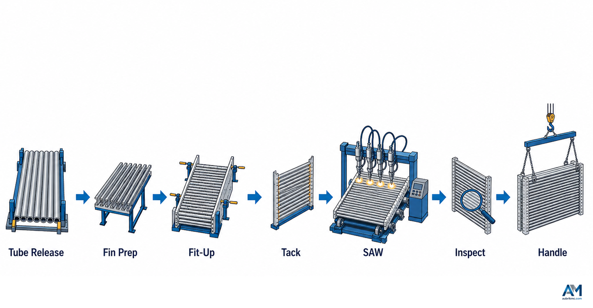
Para a construção de paredes membranadas de caldeiras, use a sequência a seguir como estrutura de planejamento, e não como roteiro de fabricação universal. Os pontos de espera efetivos dependem do desenho técnico, do material, do procedimento de soldagem, do plano de inspeção e do layout da fábrica. O objetivo é mostrar o que precisa ser liberado antes que a etapa seguinte processe a peça.
- Na liberação dos materiais, confira os tubos, as barras de membrana, o sistema de material de adição/fluxo e os documentos com revisão controlada. A semelhança visual de um insumo não comprova sua equivalência.
- Durante a preparação, confirme as características que afetam o ajuste e a montagem da junta e o comportamento do arco, incluindo retilineidade, geometria das barras de membrana, condição do corte e estado especificado de preparação da superfície. Registre as dimensões em mm ou na unidade exigida pelo desenho técnico, em vez de convertê-las informalmente na estação.
- Durante o carregamento e o ajuste e a montagem da junta, posicione as peças, verifique o alinhamento e a condição da junta e, em seguida, registre a liberação. Não use a máquina como um calibrador motorizado para forçar o posicionamento de insumos não conformes.
- Na soldagem controlada, selecione a configuração autorizada, confirme os consumíveis e a conexão à massa e monitore as variáveis exigidas pelo procedimento ou plano de controle.
- Durante a limpeza e a preparação do acesso, remova qualquer material que oculte a solda ou interfira no passe seguinte, na inspeção ou na etapa de movimentação de peças.
- Na inspeção e na decisão, avalie a condição da solda e as dimensões do painel pelo método definido para o projeto. Registre a aceitação, o encaminhamento para reparo ou a análise da engenharia.
- Durante a descarga e a transferência para a etapa seguinte, proteja o painel contra danos de movimentação ou deformação descontrolada e mantenha a rastreabilidade vinculada à peça de trabalho.
A ISO 13920:2023 estabelece classes gerais de tolerância para construções soldadas, mas seu registro público também coloca o desenho técnico e os requisitos funcionais no centro da definição das tolerâncias aplicáveis. Para um painel membrana, isso significa que a verificação de liberação deve citar o desenho técnico e os documentos de aceitação do comprador, em vez de uma tolerância copiada de um painel sem relação com o projeto.
Para fins de rastreabilidade, registre a procedência dos tubos e o diâmetro real sempre que a especificação do material ou o plano do comprador assim exigir. O mesmo conjunto controlado pode ser chamado de painel de parede membranada nos documentos de suprimentos.
O fluxograma de equipamentos para produção de caldeiras é uma referência útil, pois a soldagem dos painéis normalmente apresenta interdependências com a preparação da produção anterior e com a fabricação metalmecânica posterior. O fluxograma pressupõe que uma única fábrica usará apenas algumas das estações de equipamentos listadas.
Mapa de restrições da linha de painéis em 7 etapas: identifique o verdadeiro gargalo
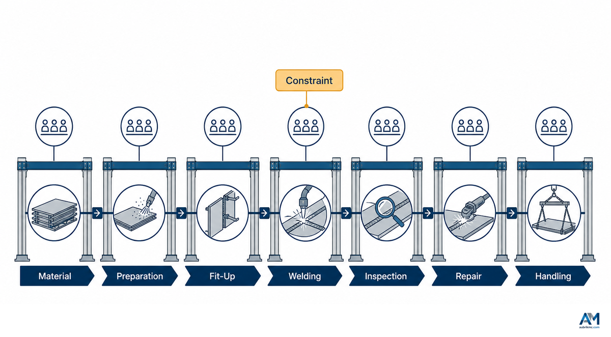
A produtividade útil é determinada pela etapa repetível mais lenta que libera peças aceitáveis para a combinação de produtos pretendida. Um ciclo de soldagem rápido pode coexistir com uma linha lenta se as esperas no ajuste e na montagem da junta, as interrupções de consumíveis, as filas de inspeção, os reparos ou a descarga retiverem regularmente o painel seguinte.
| Etapa/observação | Possível restrição | Medição | Pergunta corretiva do responsável |
|---|---|---|---|
| 1. Fila de liberação dos materiais | Divergência na rastreabilidade ou na documentação | Tempo de espera e lotes rejeitados por motivo | Qual registro está faltando para que a preparação possa começar? |
| 2. Conclusão da preparação | Pendências relacionadas à condição ou à limpeza dos tubos/barras de membrana | Conjuntos prontos por turno e liberação na primeira verificação | Qual característica do insumo causa mais retenções? |
| 3. Liberação do ajuste e da montagem da junta | Alinhamento, condição da junta ou carregamento no dispositivo de fixação | Tempo entre o carregamento e a liberação e quantidade de ajustes | O atraso é causado pela geometria do insumo, pelo método ou pelo acesso? |
| 4. Ciclo ativo de soldagem | Curso, partidas/paradas ou interrupção do movimento | Tempo de arco aberto, tempo sem arco e motivo da parada | Qual parada é controlada pela estação? |
| 4. Continuidade dos consumíveis | Fornecimento, condicionamento ou reposição do arame de soldagem/fluxo | Interrupções e tempo decorrido para reposição/recuperação | A reposição pode ocorrer sem interromper a sequência de liberação? |
| 5. Liberação da inspeção | Resfriamento, acesso, verificação dimensional ou fila de inspetores | Tempo entre a conclusão do ciclo e a decisão | Quais evidências podem ser preparadas durante o ciclo — e não depois dele? |
| 6. Reparo/decisão | Defeito recorrente ou demora na decisão da engenharia | Eficiência da produção, aceitação na primeira inspeção e horas de retrabalho por causa | O problema está no material, no ajuste e na montagem da junta, no processo, no movimento ou na inspeção? |
| 7. Movimentação/descarga | Ponte rolante, rolete, espaço no piso ou bloqueio na etapa seguinte | Tempo entre a liberação e a desobstrução e ocorrências de ciclo bloqueado | O painel seguinte pode entrar enquanto o anterior é transferido? |
| Troca entre etapas | Variação da combinação de produtos e verificação da configuração | Tempo entre a última peça aprovada e a primeira peça aprovada por família de produtos | Quais configurações, dispositivos de fixação e verificações realmente mudam? |
Exemplo prático sem dados de produção inventados: suponha que, na maioria dos ciclos, o carro de soldagem termine antes da liberação do ajuste e da montagem da junta, enquanto a inspeção e a descarga permaneçam desobstruídas. Aumentar a velocidade do curso geraria mais espera na estação de soldagem, e não mais painéis liberados. Meça novamente todas as sete etapas após um teste que reduza a variação ou o tempo de liberação do ajuste e da montagem da junta. Essa lógica identifica onde testar; ela não prevê um ganho percentual.
Padronize todas as comparações de produtividade. A expressão “painéis por dia” é incompleta se o comprimento e a largura do painel, a geometria dos tubos/barras de membrana, a sequência de soldagem, a qualidade aceita, a duração do turno, a combinação de trocas e o tratamento dos retrabalhos também não estiverem definidos. Adote o mesmo cuidado com a quantidade de tochas e a velocidade de curso anunciada.
Cenário ilustrativo apenas para padronização: se duas propostas indicarem disponibilidade de 90% e 95%, mas uma delas excluir uma janela de troca planejada de 10%, esses números não serão comparáveis. Substitua esses percentuais de exemplo por dados específicos da fábrica; eles não são declarações de desempenho da Aubrik nem metas de aceitação.
Quando a liberação dimensional fizer parte de uma etapa, use o desenho técnico do comprador e a estrutura geral de tolerâncias da ISO 13920:2023 aplicável somente quando os documentos vigentes realmente a invocarem.
Defina uma janela de processo sem tratar as configurações da máquina como uma WPS
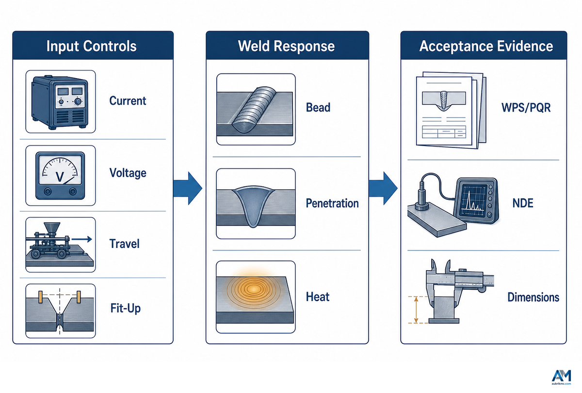
Uma janela de processo vincula as variáveis ajustáveis a um resultado aprovado e define como os desvios devem ser tratados. O posicionamento preciso da tocha pode contribuir para uma solda uniforme, mas nenhuma dessas expressões representa um resultado de aceitação até que os exames e as verificações dimensionais especificados sejam aprovados. Os fornecedores de equipamentos explicam os controles disponíveis; a organização responsável pela soldagem qualifica e aprova o procedimento aplicável; o contrato identifica as evidências de aceitação.
Um estudo de acesso aberto de 2024 sobre o aço P355N usado em vasos de pressão variou a corrente de soldagem a arco submerso de 300 A a 700 A dentro de sua própria configuração experimental e relatou mudanças na penetração, no comportamento sob tração, na dureza e na microestrutura. Esses resultados mostram por que as variáveis devem ser avaliadas em conjunto. Eles não estabelecem uma faixa de configuração para a produção de conjuntos de tubos e barras de membrana.
Exemplo de limite específico do estudo: nesse experimento com P355N, ocorreu penetração incompleta a 300 A e 400 A; a Tabela 1 informou tensão máxima de 496,29 MPa a 500 A e deformação de 18,67% a 600 A, dentro da faixa experimental de 300 A a 700 A do artigo. Esses resultados não podem ser transferidos para a produção de painéis. Eles mostram por que uma janela de procedimento deve ser verificada com a junta, o material e a base de aceitação reais.
Outro estudo de 2024 revisado por pares sobre chapas ASTM A516 Grade 70 avaliou corrente, tensão, velocidade de curso, fluxo de calor, geometria da zona termicamente afetada, microestrutura e dureza como um sistema acoplado. A lição transferível é o método: vincular os parâmetros a resultados verificados, e não reproduzir a receita numérica do estudo.
| Variável ou condição | Por que está vinculada | Evidência a registrar | Limite de aprovação |
|---|---|---|---|
| 1. Corrente | Interage com o arame de soldagem, o curso, o aporte térmico, o perfil de fusão e a deposição. | Valor nominal e tendência real, quando disponíveis | WPS aplicável e controle de engenharia |
| 2. Tensão | Altera o comportamento do arco e deve ser avaliada em conjunto com a corrente e a geometria. | Faixa autorizada e desvios registrados | Procedimento aplicável |
| 3. Velocidade de curso | Afeta o tempo por comprimento e a distribuição de calor; uma velocidade maior não é automaticamente aceitável. | Movimento comandado e real, além do resultado da solda | Procedimento e resultado da aceitação |
| 4. Sistema de arame de soldagem e fluxo | A seleção e a condição dos consumíveis afetam o comportamento do arco e do metal depositado. | Classificação, fabricante, lote e registro da condição | Procedimento e controle de compras |
| 5. Posição/extensão livre do eletrodo | A posição do cabeçote, a condição do contato e a distância até a peça afetam a estabilidade. | Verificação da configuração e da manutenção | Procedimento/folha de configuração |
| 6. Ajuste e montagem da junta | Folga, alinhamento, contato e imobilização alteram a junta apresentada ao arco. | Liberação antes da soldagem e registro de exceções | Critérios do desenho técnico e de ajuste e montagem da junta |
| 7. Superfície e conexão à massa | A contaminação ou um caminho de retorno instável pode comprometer um teste de configuração. | Liberação da preparação e verificação da conexão | Instrução de trabalho |
| 8. Controles de sequência/temperatura entre passes | Múltiplas soldas e o histórico térmico podem afetar a geometria e o trabalho subsequente. | Sequência dos passes, tempos e evidências da temperatura especificada | Procedimento aplicável |
| 9. Resultado verificado | Uma configuração só é útil quando os resultados exigidos para a solda e as dimensões são aprovados. | Resultados da inspeção vinculados aos parâmetros registrados | Decisão da garantia da qualidade e aceitação contratual |
A velocidade de curso ou as altas taxas de deposição não devem ser tratadas como melhorias isoladas: o tamanho e a qualidade exigidos para a solda ainda precisam ser aprovados, enquanto a composição dos consumíveis altera o comportamento da deposição e da penetração.
Condição de parada: se a equipe não conseguir identificar o desenho técnico vigente, a revisão do procedimento, a especificação dos consumíveis e o método de aceitação, não faça “ajustes até que pareça certo”. Resolva primeiro a lacuna de documentação e responsabilidade.
Matriz de defeitos e controles com 10 causas
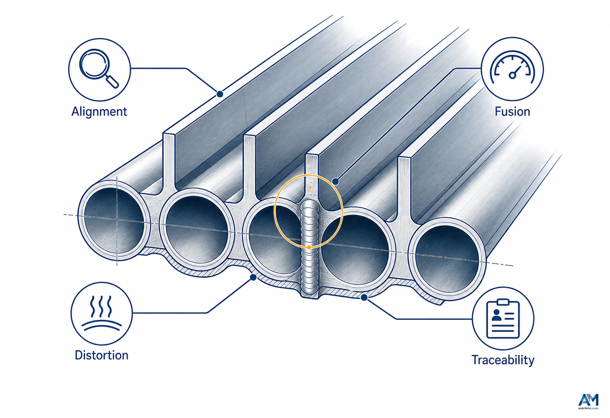
Na produção de painéis de paredes d’água de caldeiras, um sintoma visível na solda ou no painel raramente comprova uma única causa raiz. Comece a análise separando três grupos de evidências: materiais e ajuste e montagem da junta, processo e equipamentos de soldagem e resultados dimensionais ou de inspeção após a soldagem. Altere apenas um fator controlado e somente depois de preservar as evidências existentes.
Como minimizar os defeitos de soldagem em painéis de tubos de caldeiras?
Libere insumos consistentes, execute o procedimento aplicável, registre as variáveis críticas, inspecione nos pontos de espera definidos e classifique as não conformidades recorrentes com base nas evidências, e não apenas na aparência. A prevenção melhora quando os registros de preparação, ajuste e montagem da junta, condição dos consumíveis, movimento, inspeção e reparo podem ser vinculados ao mesmo painel.
| Observação | Possíveis fatores contribuintes a investigar | Primeira verificação das evidências | Registro a manter/limite para escalonamento |
|---|---|---|---|
| 1. Indicação de falta de fusão | Condição apresentada pela junta, posição, distribuição de calor, curso, compatibilidade entre consumível e processo | Liberação do ajuste e da montagem da junta, além do registro dos parâmetros reais e da posição do cabeçote | Resultado da inspeção; a engenharia de soldagem define a ação corretiva |
| 2. Indicação de porosidade | Condição da superfície, condição dos consumíveis, cobertura/movimentação do fluxo, interrupção do processo | Evidências da preparação dos materiais e do lote/condição dos consumíveis | Mapa das indicações; a decisão segue o processo de aceitação especificado |
| 3. Mordedura | Posição, interação entre corrente/tensão/curso, geometria da junta | Compare as configurações reais e a preparação com a base aprovada | Localização e extensão; não prescreva o reparo com base nesta tabela |
| 4. Penetração incompleta | Ajuste e montagem da junta, formato da junta, interação entre corrente e curso, posição de trabalho | Medição precisa da junta e histórico do processo no comprimento afetado | Evidências da inspeção da qualidade da solda e análise da engenharia |
| 5. Penetração excessiva ou perfuração | Geometria do insumo, folga local, interação entre energia e curso, escolha do eletrodo | Compare o ajuste e a montagem locais da junta com a condição registrada do processo | Localização exata, lote dos insumos e revisão do procedimento |
| 6. Cordão irregular ou instabilidade do arco | Avanço do arame de soldagem, condição do contato, conexão à massa, perfil dos pontos de fixação, percurso do fluxo, interrupção do movimento | Histórico de alarmes/paradas, percurso de avanço, conexão e inspeção da configuração | Preserve os horários dos eventos antes de reinicializar o equipamento |
| 7. Desalinhamento entre tubos e barras de membrana | Geometria dos insumos, desgaste dos posicionadores, método de carregamento, imobilização, movimentação térmica | Registro dimensional antes e depois da soldagem | Característica do desenho técnico e método de medição utilizado |
| 8. Distorção do painel | Curvatura ou retilineidade inicial, imobilização, sequência, distribuição de calor, movimentação antes da liberação | Geometria etapa por etapa, não apenas a medição final | Momento da medição e condição de apoio |
| 9. Problema no manuseio da escória ou do fluxo | Condição do fluxo, caminho de recuperação, cobertura, acesso para limpeza, interrupção | Inspeção do manuseio dos consumíveis e da recuperação/limpeza | Lote, condição e comprimento afetado; siga as regras do procedimento |
| 10. Retrabalho recorrente | Família de insumos sem controle, erro de troca, ciclo de realimentação deficiente, decisão repetida | Pareto por família de produtos, etapa, turno e causa verificada | Registro de ações corretivas; a administração é responsável pela resolução sistêmica |
Esta matriz é deliberadamente interrompida antes das instruções de reparo. Os métodos de aceitação e os processos de reparo variam de acordo com o contrato, a norma, o material, a junta e o procedimento qualificado. Uma tabela de diagnóstico pode organizar as evidências; ela não pode autorizar reparos na produção.
Se o plano de inspeção exigir ensaio ultrassônico, registre o método, a cobertura, a base de aceitação e a identificação do painel; a própria máquina não determina a decisão.
Onde termina a atuação da estação de soldagem de painéis: tarefas que exigem outra etapa do processo
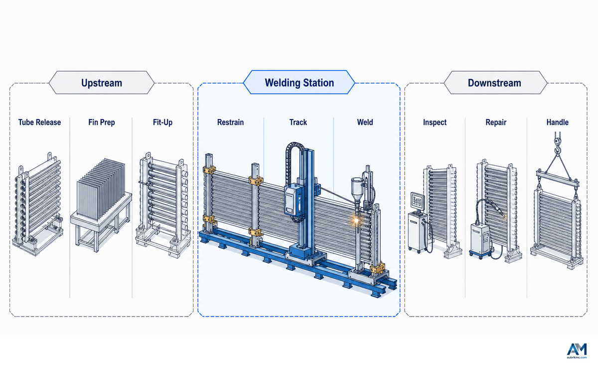
Na soldagem de painéis de tubos, uma junta de soldagem longa e repetitiva entre tubos e barras de membrana representa um problema de produção diferente de uma junta de extremidade de tubo, um reparo localizado, um componente anexado, um revestimento por soldagem ou uma solda curta com acesso obstruído. Defina o limite com base no acesso à junta, na geometria, na base aplicável para qualificação do procedimento, nos requisitos de qualidade e na movimentação de peças, e não no desejo de fazer uma única máquina executar todas as soldas.
| Tarefa | Por que pode ficar fora da estação de painéis | Próxima pergunta |
|---|---|---|
| Conexão da extremidade do tubo ou do coletor | Geometria da junta, acesso, posição e processo de inspeção diferentes | Qual processo qualificado e dispositivo de fixação abrangem esta junta? |
| Reparo localizado de defeitos | Exige uma decisão autorizada e acesso controlado a um local específico | Qual procedimento de reparo e reinspeção estão aprovados? |
| Juntas de soldagem curtas ou interrompidas | As partidas/paradas e as obstruções podem ter mais influência do que o curso contínuo | Uma estação automatizada ou manual diferente controlaria melhor a junta? |
| Revestimento por soldagem ou revestimento metálico por soldagem | A função do metal depositado e a base do procedimento diferem das utilizadas na união entre tubos e barras de membrana | Quais materiais, diluição, espessura e exames são aplicáveis? |
| Componentes anexados e olhais | A imobilização local, o acesso e o caminho do calor diferem dos da junta de soldagem principal | Em que ponto do roteiro esses componentes devem ser adicionados? |
| Geometria curva não padronizada | O percurso e a imobilização da peça de trabalho podem exceder os limites previstos no projeto da linha | O dispositivo de fixação e o movimento podem ser validados para o formato real? |
Esta seção não classifica SAW, MIG/MAG, soldagem robotizada ou métodos manuais por preço ou desempenho anunciado. Essas são decisões de configuração vinculadas aos limites dimensionais e técnicos reais dos produtos. O polimento, o revestimento e o trabalho nas extremidades dos tubos após essa etapa também exigem processos próprios. Para decisões sobre escopos adjacentes, consulte a máquina de curvamento de painéis da Aubrik para a geometria posterior do painel e sua máquina de soldagem tubo a tubo para o processamento das juntas de extremidade. A equipe de suprimentos deve primeiro identificar quais famílias de juntas a estação de painéis precisa atender e quais devem ser processadas em outro local.
Integração e utilidades: os requisitos que os compradores descobrem tarde demais
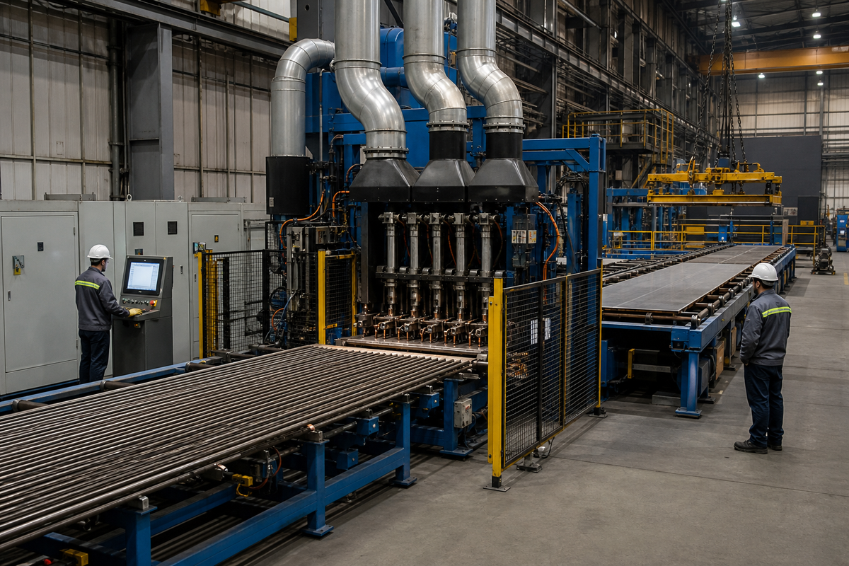
A aceitação do equipamento costuma se concentrar na máquina energizada, enquanto a interface com a produção permanece indefinida. Uma linha horizontal pode concluir um ciclo a seco isolado e, ainda assim, não alcançar o fluxo planejado porque a peça de trabalho não consegue chegar, os consumíveis não podem receber manutenção, os registros não são capturados ou o painel concluído não consegue sair.
Nos locais de trabalho dos Estados Unidos, a OSHA 1910.252 exige que as operações de soldagem controlem os riscos de incêndio e disponham de ventilação adequada aos fumos de soldagem, gases, poeiras e condições do ambiente de trabalho. Isso justifica definir a exaustão localizada e os controles contra incêndio como itens explícitos da interface. A norma não estabelece uma vazão de ar universal nem substitui a análise da regulamentação local e da higiene ocupacional.
- Defina os limites do produto: diâmetro dos tubos e faixa de aletas, largura e comprimento dos painéis, massa, família de juntas e frequência de variação dos produtos.
- Mapeie o fluxo de materiais: direção de recebimento, preparação, carregamento, descarregamento, pontos de içamento e destino a jusante.
- Verifique a fundação e os acessos: carga sobre o piso, alinhamento, ancoragem, espaço livre para manutenção, rota do operador e zonas protegidas.
- Documente a interface elétrica: características da alimentação, distribuição, dispositivos de proteção, aterramento e responsabilidade pela conexão.
- Atribua os controles de fumos de soldagem e incêndio: conceito de exaustão localizada, ar de reposição, controles para trabalhos a quente, gerenciamento de materiais combustíveis e análise dos requisitos da jurisdição.
- Planeje o sistema de consumíveis: armazenamento do arame de soldagem e do fluxo, condicionamento quando necessário, avanço, recuperação, limpeza e rastreabilidade dos lotes.
- Especifique controles e dados: receitas, níveis de acesso, alarmes, intertravamentos, I/O, registros de produção, backup e limites de responsabilidade pela cibersegurança.
- Relacione os serviços auxiliares: ar comprimido, resfriamento, exaustão localizada ou outros serviços somente quando exigidos pela configuração selecionada.
- Planeje o suporte à manutenção: isolamento seguro, acesso às peças de desgaste, instrumentos que exigem calibração ou verificação, suporte a diagnósticos e estratégia de peças de reposição.
- Defina a transferência para a próxima etapa: critérios de resfriamento ou contenção, posição para inspeção dimensional, marcação, rastreabilidade, apoio para armazenamento e operação seguinte.
Atribua cada interface ao comprador, ao fornecedor ou a terceiros antes da emissão do pedido. “Por terceiros” não identifica um responsável. Para cada item, indique quem fornece os dados, quem projeta a interface, quem a instala e quais evidências comprovam sua conclusão.
Matriz de aceitação da RFQ para painéis membranados com 12 dados de entrada

Uma RFQ pronta para decisão começa com evidências de produção, não com uma quantidade solicitada de tochas de soldagem. Os 12 dados de entrada abaixo permitem que o fornecedor explique uma configuração adequada, preservando a responsabilidade do comprador pelos requisitos do produto, pela base do procedimento de soldagem e pelos critérios de aceitação.
Inclua referências como ASME BPVC Section IX e ISO 13920:2023 na RFQ somente quando o código de construção aplicável, o desenho técnico, o contrato e o plano de aceitação determinarem sua aplicação.
Converta as faixas publicadas em evidências de aceitação:
Em julho de 2026, a página de configurações comerciais da Aubrik publica uma faixa específica do fornecedor com velocidade de soldagem de 0,8 m/min a 2,0 m/min, rastreamento da junta de soldagem com precisão de ±0,5 mm, espessura de painéis de 3 mm a 16 mm, diâmetro externo de tubos de 22 mm a 108 mm, largura padrão de painéis de 1.600 mm e largura personalizada de até 2.500 mm, além de diâmetro do arame de soldagem de 2,4 mm ou 3,2 mm. Esses valores descrevem a configuração publicada pela Aubrik, não limites universais do processo nem resultados garantidos.
Para um teste dos limites específicos do fornecedor, a RFQ pode solicitar evidências nas condições inferiores e superiores aplicáveis: espessuras de 3 mm e 16 mm, diâmetros externos de tubos de 22 mm e 108 mm, larguras de 1.600 mm e 2.500 mm, arames de soldagem de 2,4 mm e 3,2 mm, além de velocidades registradas entre 0,8 m/min e 2,0 m/min. Use somente as condições permitidas pelo desenho técnico do comprador, pela base do procedimento de soldagem e pelo escopo acordado do FAT.
| Dado de entrada | O comprador fornece | O fornecedor confirma | O FAT comprova | Registro de entrega |
|---|---|---|---|---|
| 1. Variedade de produtos | Famílias representativas de painéis e frequência prevista | Famílias abrangidas e método de troca de configuração | Testes representativos acordados | Matriz de configurações e produtos |
| 2. Materiais dos tubos e das aletas | Especificações, classes dos materiais e necessidades de rastreabilidade | Premissas de compatibilidade e exclusões | Material de teste correto e identificado | Registros de materiais e consumíveis |
| 3. Faixa de dimensões | Dimensões dos tubos, das aletas e das juntas, com revisão | Faixa operacional e ferramental necessário | Condições-limite selecionadas | Faixa aprovada e lista de ferramental |
| 4. Limites dos painéis | Dados de largura, comprimento, massa, apoio e içamento | Solução de carregamento, contenção, curso e descarregamento | Movimentação segura dos painéis acordados | Instruções de layout e movimentação de peças |
| 5. Geometria da junta | Desenhos técnicos, critérios de ajuste e montagem da junta e requisitos de ponteamento e sequência | Critérios do dispositivo de fixação e de acesso aos cabeçotes | Preparação repetível e juntas concluídas | Folhas de preparação e desenhos técnicos |
| 6. Definição da produção | Duração do turno, variedade de produtos, paradas planejadas e tratamento da inspeção e do retrabalho | Premissas do ciclo e tempo excluído | Tempos medidos em cada ponto de controle e unidades aceitas | Registro de teste assinado com as premissas |
| 7. Base do procedimento de soldagem | Responsabilidade pela WPS/PQR aplicável e plano de qualificação | Controles disponíveis e captura de dados | Execução da base de teste autorizada | Registros de preparação vinculados à revisão |
| 8. Consumíveis | Classificações aprovadas e regras de armazenamento e rastreabilidade | Interfaces de avanço e recuperação e premissas de capacidade | Fornecimento estável durante o teste acordado | Percurso dos consumíveis e registro de manutenção |
| 9. Critérios dimensionais | Características do desenho técnico, tolerâncias, condição de apoio e precisão da medição | Contribuição e limites do dispositivo de fixação e do controle | Dimensões registradas antes e depois da soldagem | Formulários de inspeção e método de medição |
| 10. Critérios de solda e inspeção | Método de exame, amostragem, aceitação e fluxo de destinação | Suporte ao acesso e aos dados do processo | Inspeção acordada do resultado do teste | Relatórios vinculados à identificação do painel |
| 11. Utilidades e controles | Serviços disponíveis, regras da fábrica, interfaces e política de dados | Cargas, pontos de conexão, I/O, intertravamentos e exclusões | Verificações funcionais e das interfaces de segurança dentro do escopo acordado | Desenhos técnicos conforme construído, backups e ajustes |
| 12. Pacote de suporte | Idioma, público do treinamento e expectativas de resposta e peças de reposição | Manuais, treinamento, garantia, peças de reposição e escopo do suporte | Análise da documentação e exercícios para operadores e equipe de manutenção | Dossiê aceito e lista de pendências |
Quais dados de produção o comprador deve preparar antes de aceitar uma linha de soldagem de painéis membranados?
Prepare a matriz de famílias de produtos, os materiais e desenhos técnicos reais, as regras de juntas e de ajuste e montagem, a responsabilidade pelo procedimento de soldagem, os consumíveis, os critérios dimensionais e de aceitação das soldas, as premissas dos turnos, as utilidades, as interfaces de controle, o treinamento, as peças de reposição e os documentos de entrega. Em seguida, escolha testes de FAT que representem as condições-limite mais difíceis e a família de produtos mais comum, não apenas um corpo de prova conveniente para demonstração.
Regra mínima viável para a RFQ
Se uma promessa de produção não puder ser vinculada a um produto definido, a uma solda e geometria aceitas, a um modelo de turnos, a um fluxo de inspeção e ao tratamento do retrabalho, ela ainda não será um compromisso de produção comparável. Solicite ao fornecedor que informe cada premissa junto ao resultado.
Depois de definir os 12 dados de entrada, consulte as configurações das máquinas de soldagem de painéis membranados da Aubrik. Essa página comercial é o local correto para opções de equipamentos, especificações do fornecedor, personalização e questões sobre cotações; este guia permanece como referência para o processo e a aceitação.
Perguntas frequentes
Para entender o escopo de qualificação e tolerâncias nas respostas abaixo, consulte os documentos aplicáveis ao projeto em conjunto com a ASME BPVC Section IX e a ISO 13920:2023. Esses registros públicos são referências de escopo, não critérios de aceitação do projeto.
O que são painéis membranados de tubos de caldeira e por que eles são importantes?
Painéis membranados são conjuntos nos quais tubos são unidos por aletas ou barras para formar uma seção contínua de parede. Seu projeto e sua função exatos são definidos pelo pacote de engenharia da caldeira. Do ponto de vista da fabricação, a geometria unida faz com que a condição dos tubos, a preparação das aletas, o ajuste e a montagem da junta, a integridade das soldas, as dimensões dos painéis e a rastreabilidade façam parte de um único fluxo de produção controlado. Essa função de parede compartilhada torna a liberação dimensional e a rastreabilidade tão importantes quanto a aparência dos cordões durante a montagem posterior da caldeira, a documentação das partes sob pressão e os trabalhos finais de inspeção.
Qual processo de soldagem é usado em painéis membranados de caldeiras?
Processos de arco submerso e com gás de proteção podem ser empregados em sistemas de produção de painéis, dependendo do projeto da junta, do material, do acesso, do procedimento de soldagem e da configuração do equipamento. Somente o nome do processo não determina a escolha da máquina. Os compradores devem fornecer os limites do produto e a base de qualificação e, depois, verificar se o processo e os controles propostos conseguem produzir as evidências especificadas.
Como a automação afeta a consistência das soldas em painéis membranados?
A automação pode repetir de forma mais consistente os movimentos coordenados, o avanço do arame de soldagem, o curso e as configurações armazenadas do que uma sequência manual sem controle. Ela não pode garantir resultados consistentes quando variam a geometria de entrada, a condição superficial, o ajuste e a montagem da junta, os consumíveis ou as regras de inspeção. A automação alcança seu melhor desempenho quando os critérios de liberação a montante e as evidências a jusante são igualmente rigorosos. A consistência deve ser avaliada entre as entradas liberadas e os resultados aceitos, usando a mesma família de produtos, revisão do procedimento de soldagem, método de inspeção e condição de apoio em cada teste; preserve o resultado nos registros de análise da produção.
Quais são as principais verificações de controle da qualidade na soldagem de painéis membranados?
Verifique a identificação dos materiais, a geometria dos tubos e das aletas, a condição superficial, o ajuste e a montagem da junta, a configuração autorizada do processo, a rastreabilidade dos consumíveis, as variáveis registradas, o exame das soldas, as dimensões após a soldagem e a destinação final. Vincule cada resultado ao painel, à revisão do desenho técnico, à base do procedimento de soldagem, ao método de medição e ao responsável pela análise, para que qualquer exceção possa ser rastreada e solucionada.
O que deve ser registrado durante o FAT de um painel membranado?
Registre o produto e o material exatos do teste, as revisões do desenho técnico e do procedimento de soldagem, a preparação e os consumíveis, o estado das utilidades e do software, as verificações funcionais ou de segurança, os tempos em cada ponto de controle, as interrupções, as evidências reais do processo, as dimensões antes e depois da soldagem, os resultados das inspeções, os retrabalhos ou itens pendentes e as premissas por trás de qualquer resultado de produção. Inclua o fluxo de carregamento e descarregamento, o acesso para manutenção, o histórico de alarmes e paradas, as ações do operador, a condição de apoio durante a medição, além do responsável e da data de conclusão de cada constatação não solucionada antes de encerrar o teste ou programar um novo teste.
Preserve o registro bruto dos tempos, além do resumo. Vincule cada resultado de inspeção ao painel de teste e às respectivas configurações, identifique o responsável por cada ação pendente e informe se um novo teste será necessário. Preserve a aceitação assinada em vez de depender de um vídeo ou de uma declaração de aprovação ou reprovação.
Quando uma máquina de soldagem de painéis membranados não é a ferramenta correta?
Uma máquina de soldagem de painéis membranados pode não ser a estação correta quando o trabalho envolve uma junta entre extremidades de tubos, um reparo localizado, um componente de ligação, revestimento por soldagem, uma junta de soldagem curta e obstruída ou uma geometria fora dos limites previstos do dispositivo de fixação e dos movimentos. Encaminhe essas juntas para uma decisão separada de engenharia e de procedimento de soldagem. Não tente processá-las na linha de painéis apenas porque envolvem soldagem.
Transforme a seleção da máquina em uma decisão de produção controlada

Uma sequência confiável é simples de descrever e exigente de executar: libere as entradas, ajuste e restrinja a peça, execute o procedimento qualificado aplicável, preserve as evidências do processo, inspecione a solda e o painel, dê a destinação adequada às exceções e libere o fluxo a jusante. Quatro recursos de trabalho, o fluxo de 7 etapas, o mapa de restrições de 7 pontos de controle, a matriz de diagnóstico com 10 causas e a matriz de RFQ com 12 dados de entrada atribuem um responsável visível a cada decisão.
A capacidade da máquina continua sendo importante. Ela somente se torna relevante depois que o comprador define o que a linha deve produzir e como os resultados aceitáveis serão comprovados. Mantenha o trabalho de configuração e cotação na página da solução comercial e use este guia como a lógica operacional compartilhada pelas equipes de produção, engenharia de soldagem, garantia da qualidade, manutenção e suprimentos.
Referências e fontes
- ASME, BPVC Section IX: qualificações para soldagem, brasagem e fusão (registro da edição de 2025)
- ISO, ISO 13920:2023, tolerâncias gerais para construções soldadas
- Materials (2024) — influência da intensidade da corrente de soldagem a arco submerso no aço P355N
- The International Journal of Advanced Manufacturing Technology (2024) — processo SAW e observações metalúrgicas
- OSHA, 29 CFR 1910.252, requisitos gerais de soldagem
- The Fabricator, uso de arame tubular em aplicações de soldagem a arco submerso
- Canadian Metalworking, fundamentos da soldagem a arco submerso
Em alta agora