Get in Touch with Aubrik Company

Hot wire GTAW combines a tungsten arc with a filler-heating circuit to perform gas tungsten arc welding. The value is faster accepted deposition where torch access, process control and the rest of the production cycle can keep up.
- Heating: conventional resistance heating closes through wire contact with the weld pool; indirect arrangements use a different circuit. In a reported hot-wire experiment, the wire remained in continuous contact with the weld pool at a hot-wire current of 100 A.
- Equipment: welding power, wire heating, feeding, cooling and motion must work as one cell.
- Buying measure: accepted parts per shift and recoverable cost, alongside deposition rate.
Productivity increases with a reduction in the work that creates a production bottleneck. For a valve overlay, this may be deposition. For a vessel, it may be repositioning or cooling between passes. This document explains the pertinent circuits and published performance ranges. The information needed to price a working cell is also included.
Hot wire GTAW preheats a separately fed filler wire so the tungsten arc has less melting work to do. Conventional systems heat through wire-to-pool contact. Choose the process by accepted deposition, access and complete cycle time.
How hot wire GTAW heats the filler
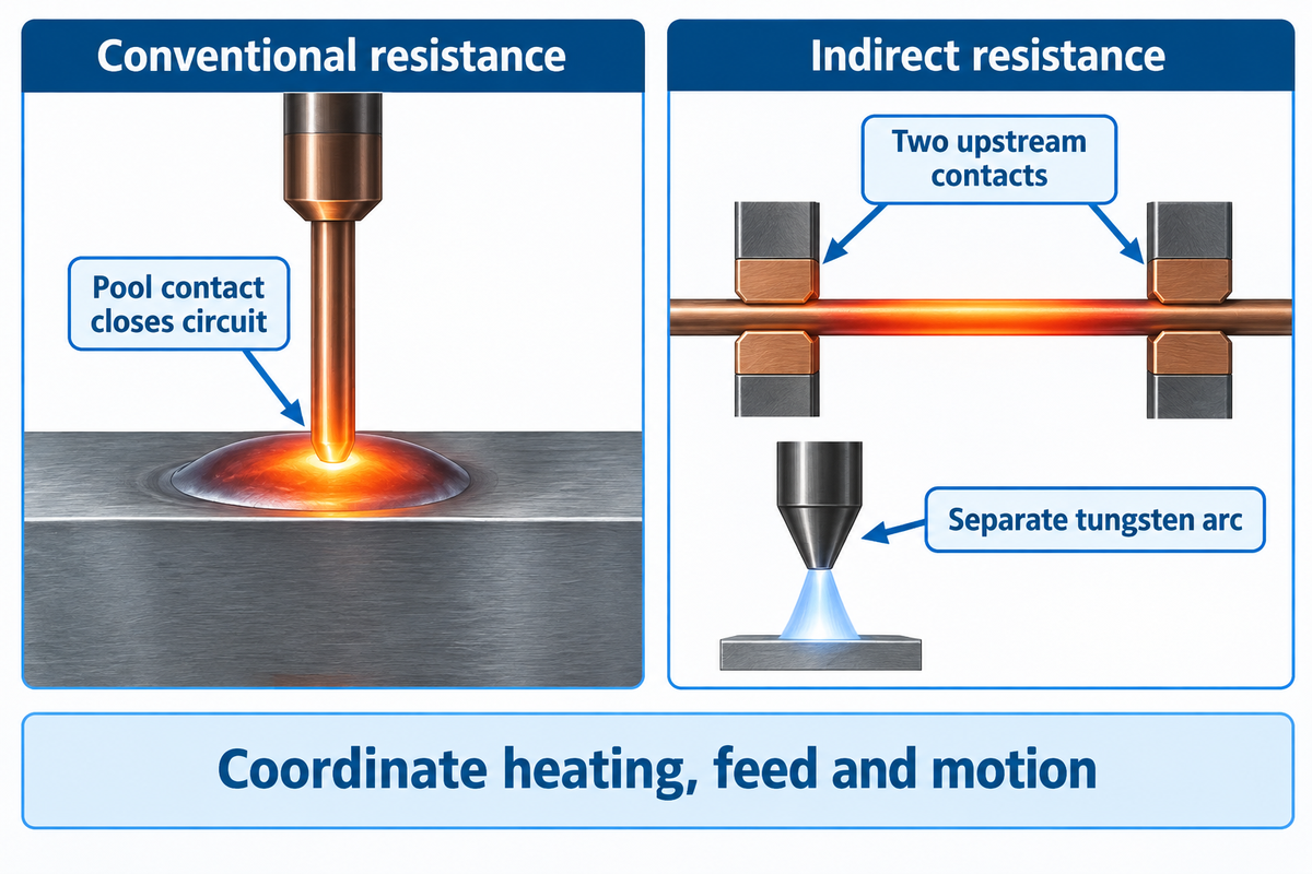
Hot wire GTAW breaks up the work required for filler melting between the tungsten arc and a filler-heating circuit. For conventional resistance systems, wire contact with the weld pool is required to complete the heating circuit.
A cold wire feeder provides filler mechanically. Adding such a feeder to a TIG machine doesn’t, in and of itself, create hot wire TIG welding. Additionally, a hot-wire system requires an adequate heating supply, current path, contact system, and coordinated controls. The tungsten electrode, unlike the consumable electrode in MIG welding, remains completely separate from the filler metal.
In conventional resistance heating, breaking the wire-to-pool connection interrupts heating. Indirect resistive designs pass current between two contacts upstream, so the wire can heat before it touches the molten weld. Ungethüm and colleagues describe these distinctions in their 2020 study of hot-wire metal transfer. Separate electrical outputs still interact through the arc, the filler and the pool.
Preheating using an auxiliary arc or an induction field offers other alternatives. The choice of wire alloy is important. Copper and aluminum are electrically more conductive than most steel filler materials, changing the demand on the heater. The same paper addresses alternatives for heating these materials. Treat the selection of the alloy, diameter and required feed as a matched combination, rather than choosing a feeder first and adding heat later.
With regard to the existing automated TIG cell, the first compatibility question is concrete: which heating circuit will the added head use, and which controller will coordinate its start, feed, travel and stop sequence? A spare output on the main power source isn’t a complete integration specification.
Hot wire TIG vs cold wire TIG and MIG
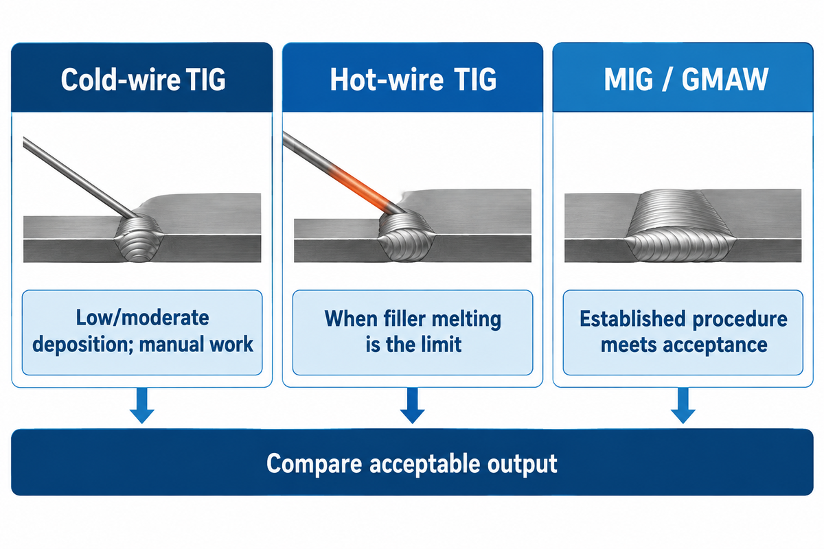
Choose hot wire TIG when filler melting is limiting an otherwise suitable TIG welding process. For low and moderate deposition requirements and manual operation, cold wire retains value. Keep MIG or controlled GMAW in the scope, when an established procedure meets the part’s acceptance requirements at useful output.
Advantages
Additional filler heating can raise melting capacity while retaining the tungsten arc process. Mechanized feeding also supports sustained deposition, and using one process through a suitable pipe weld can remove a process changeover.
Limitations
The heater, feeder and torch add integration work. Access can become more restrictive, cooling must support the duty cycle, and the added equipment needs a production workload that can use its capacity.
A 2013 Newport News Shipbuilding trial for NSRP examined manual GTAW against a handheld Tip Tig system on two 0.50″ carbon-steel butt joints. The Tip Tig joint used about one-fifth the arc time. That system employs a wire agitation and preheated filler combination, so the result pertains to that system and trial and not to preheating alone.
The report indicated access restrictions and said that its deposition rate doesn’t compete directly with pulsed GMAW for most applications. Its published heat-input comparisons excluded wire-preheating energy. There are boundaries to which processes are economically and practically acceptable when comparing a power bill or a narrow groove.
For overlay work, compare the final surface chemistry, fusion, penetration and required layer count as well as speed. Geometric dilution measures melted substrate in a cross-section and iron content measures chemistry at a given point. The two measures are different and should be interpreted as such. The GTAW surfacing and overlay acceptance guide covers that application in more detail.
Hot wire TIG deposition rate: wire flow versus finished output
Published hot-wire deposition rates describe particular wires, heads and welding conditions. In Voigt and colleagues’ induction-heating study, IHW-GTAW achieved a deposition-rate gain of up to 220 % over CW-GTAW at the same welding current within the tested configurations. Egerland and colleagues (2015) performed GTA surfacing trials and reported rates of 1.83, 2.98 and 4.23 kg/h for differing head arrangements. Use these published data to interpret configuration effects and then measure complete cycle times for the part of interest.
| Trial arrangement | Deposition | Travel | Context |
|---|---|---|---|
| Single cathode, twin wire | 1.83 kg/h | 32 cm/min | Initial cladding trials |
| Single cathode, twin wire | 2.98 kg/h | 50 cm/min | Different operating condition |
| Dual cathode, single wire | 4.23 kg/h | 80 cm/min | Different head arrangement |
Source: Egerland et al., Advanced Gas Tungsten Arc Weld Surfacing (2015), a manufacturer-associated study. These initial trials used 1.2 mm nickel-alloy filler. The substrate specimens were low-carbon S235 JR steel to Euronorm EN 10025, with a thickness of 50 mm. Later dual-cathode, twin-hot-wire tube trials reported approximately 5.6 kg/h with constant DC and 5.7 kg/h with pulsed DC. The later specimens and operating conditions differed; dividing these values doesn’t give a general upgrade multiplier.
Wire feed in m/min, travel speed in cm/min and deposited mass in kg/h address different concerns. A bigger wire feeds more volume at the same linear speed. Increased deposition rates can shorten arc time; however, accepted output includes the time spent loading, reaching the joint, waiting, inspecting and repairing.
2-Clock Hot-Wire Throughput Model
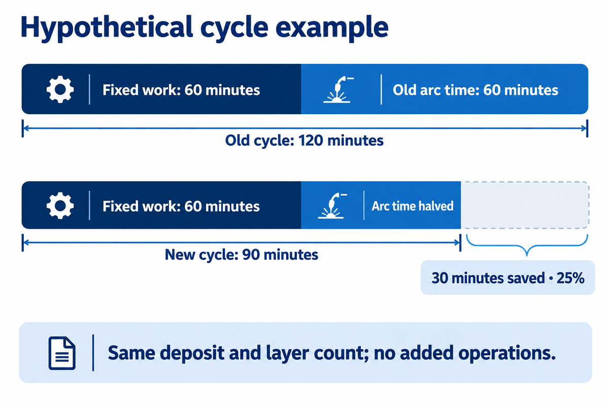
Separate the arc and the rest-of-job clocks. For the same accepted deposit and layer count, use new cycle = fixed time + old arc time ÷ demonstrated rate factor + added operations. Include additional cooling, repositioning or rework in the last term.
Filled example: assume 60 minutes of fixed work and 60 minutes of arc time per job. Doubling the arc rate, with no added operations, gives 60 + 60 ÷ 2 = 90 minutes instead of 120. That saves 30 minutes, or 25% of elapsed time. The same available hours could support 33.3% more jobs, if this operation is the production constraint and demand exists.
Interpass waiting should be recorded on the second clock. Henckell and colleagues’ 2020 GMAW additive-manufacturing study used a different welding process. This process incorporated temperature-controlled dwells between layers. In hot-wire work, Spaniol’s study also addresses the economics of thermal resting. Faster melting doesn’t necessarily shorten the interpass dwell time.
Where hot-wire GTAW fits: cladding, pipe and narrow grooves
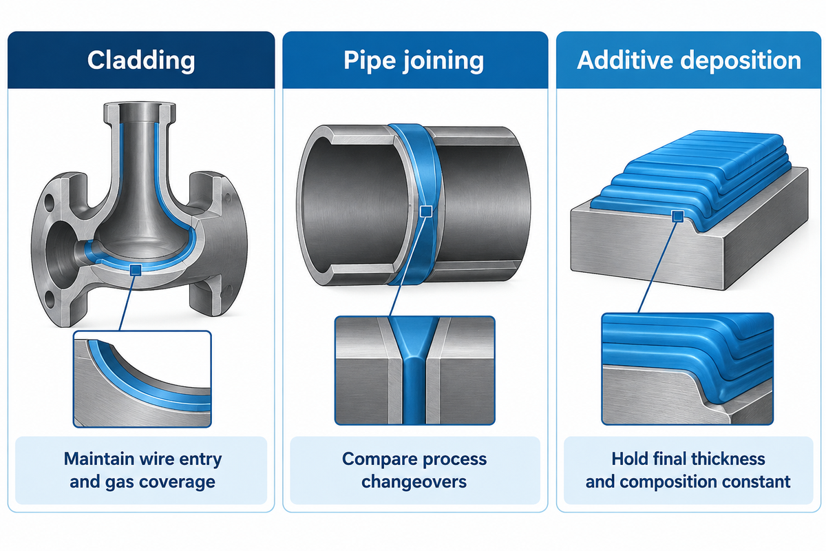
Hot-wire GTAW is appropriate for repetitive, filler-intensive work where the head can reach the joint and the procedure controls the final deposit. Published welding applications include nickel-alloy cladding, pipe joining and hot-wire-based additive deposition. A bore, a groove and an open surface impose different access limits, even when the same filler material is used.
For a valve or bore overlay, the head must maintain wire entry and gas coverage throughout the path. Egerland’s tube trials used 155 mm diameter specimens with 20 mm walls and Inconel 625-type filler. The complete head, guides and services must clear the proposed bore through every movement.
Pipe fabrication may benefit from keeping GTAW through more weld passes. Dan Allford and Dave Hebble of ARC Specialties discuss reduced changeover between a GTAW root and other fill processes in their 2019 article in The Fabricator. They compare FCAW and submerged arc welding routes; they also point out that twin or tandem SAW may have higher deposition capacity.
For what application would hot wire GTAW be used?
Corrosion-resistant weld overlay is a practical application because it requires controlled filler deposition over a repeated area. Other uses, with acceptance tests, include joining and additive manufacturing. When handling groove welding, access to the sidewall and root may outweigh the benefit of high deposition.
When another layer of cladding is needed to achieve the final chemistry, comparisons should include the added weld deposit, finishing and inspection. Hold the accepted thickness and composition constant before comparing welding speeds. Aubrik’s overlay welding process guide offers a broader view of some process choices.
Hot wire TIG equipment and cell integration

A hot-wire cell needs compatible weld power, filler heating, wire delivery, shielding, cooling and motion, all controlled by a coordinating system. Egerland’s study describes a controller that determines weld paths based on part design. The column and boom platform carries and guides the head and the process package supplies heating and welding controls.
Aubrik supplies the motion side, equipment-wise, with its column and boom welding manipulator. Workpiece movement can be provided by welding positioners. Consider the torch, feeder hardware, slides and service bundle when specifying load and clearance.
| Interface | Lead responsibility | Demonstration or deliverable |
|---|---|---|
| Tungsten arc power | Process-package supplier | Stable start, steady weld and controlled stop on the specified part |
| Wire-heating circuit | Process-package supplier | Declared heating architecture and compatible alloy/diameter range |
| Wire feed and guide | Head/feeder supplier | Stable delivery through the complete production path |
| Torch and contacts | Head supplier | Reach, insulation, access and replaceable wear parts |
| Cooling | Process integrator | Thermal performance at the intended duty cycle |
| Arc-voltage control | Controls integrator | AVC response and torch-height control over the actual path |
| Head positioning | Motion supplier | Reach, mounted load, travel and service clearance |
| Workpiece rotation | Fixture/motion supplier | Part support, rotation and synchronization under the specified load |
| Shielding and services | Integrator and plant | Gas delivery, hose routing and connections across all movements |
| Qualification and records | Plant welding/quality team | Applicable procedure tests, acceptance records and trained operators |
This division of procurement follows the process and motion architecture described in the GTA surfacing study; the responsibility assignments are a suggested quotation structure and not a standard.
Where are all the TIG robots?
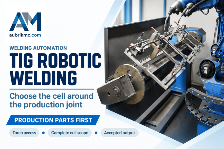
For repetitive cylindrical parts, a manipulator and a rotating fixture can provide the movement needed. A robotic TIG cell combines repeatable arm motion with coordinated feeding, arc length and thermal control. A robot arm alone can’t resolve a difficult wire entry path; the head and the fixture still need room to get to the joint.
Hot wire TIG arc blow, stubbing and other bottlenecks
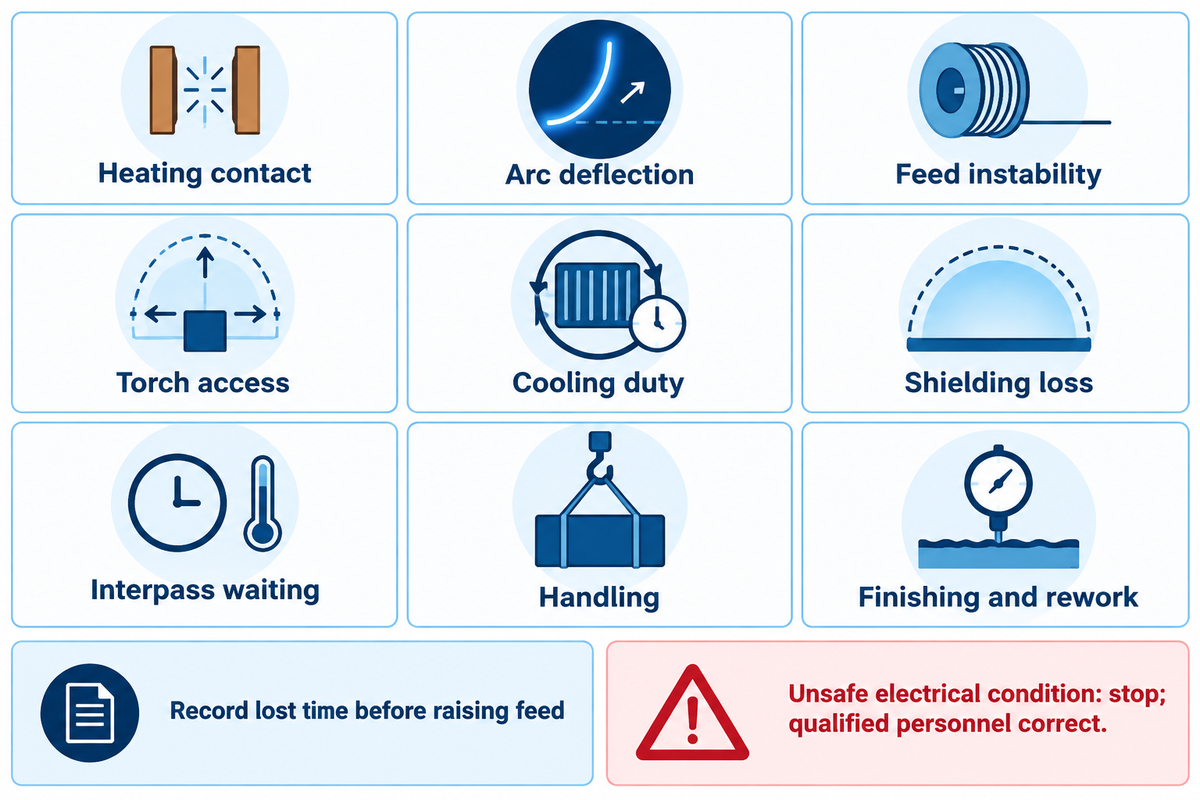
Unstable hot wire operation can originate in the heating circuit, feed path, shielding or motion. Diagnose the behavior observed against the specific architecture. During an indirect-heating experiment reported by Ungethüm and colleagues, faltering wire motion was observed without a reported effect on seam quality.
Spaniol and colleagues’ 2020 TIG hot-wire study reached wire-feed rates up to 15 m/min, but reported feeding problems from approximately 13 m/min. These results illustrate the importance of having a maximum feed specification and stable production window as differentiating buying criteria.
| Constraint | What to record | Decision it changes |
|---|---|---|
| Heating contact | Circuit type and timing of interruptions | Whether contact loss interrupts heating in this design |
| Arc deflection | Bead position relative to wire-heating operation | Process-control and current-path review |
| Feed instability | Actual feed, interruptions and accepted bead condition | Usable feed window, rather than maximum setting |
| Torch access | Clearance and visibility at the hardest part of the path | Head selection and fixture layout |
| Cooling duty | Thermal interruptions during sustained operation | Cooling package and duty-cycle compatibility |
| Shielding loss | Formation of oxides, contamination and gas-path condition | Shielding delivery and filler-handling review |
| Interpass waiting | Minutes waiting for the qualified temperature condition | Achievable cycle reduction |
| Handling | Load, turn and reposition minutes per part | Whether motion or handling needs investment first |
| Finishing and rework | Accepted thickness, rejected work and repair minutes | Net cost of an acceptable finished part |
The maps integrate the indirect-heating transfer findings and the NSRP study’s access and cooling observations. Lost time should be recorded prior to increasing feed rate. For an electrically unsafe condition, stop operation and have qualified personnel correct it; process troubleshooting isn’t a reason to improvise wiring or insulation.
Hot wire TIG cost and the time savings that pay
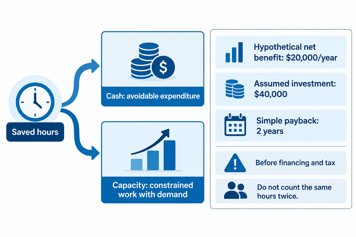
Judge hot wire investment by the net annual benefit the plant can recover. An installed quotation must include the process package, motion, integration and qualification work. Saved hours have cash value when they reduce avoidable expenditure; they provide capacity value when a constrained operation can perform additional saleable work.
Newport News Shipbuilding also approached a similar business-case boundary after their arc-time trial: equipment, procedure qualification, and welder training still lacked an economic justification. The original NSRP report noted these costs.
This worked example yields a $20,000/year net benefit under the following assumptions. Using the earlier cycle example, a 30-minute saving across 1,000 jobs per year frees 500 hours annually. If those hours replace genuinely avoidable expenditure at an assumed $50/hour, gross savings are $25,000/year. Subtracting an assumed $5,000/year of extra operating cost leaves that net benefit.
At an assumed $40,000 incremental installed investment, simple payback is $40,000 ÷ $20,000 = 2 years, before financing and tax. A finance manager should adjust these assumptions based on the actual quote, wire and consumable costs, maintenance and energy costs, and realized labor savings.
Assuming paid hours stay the same and there are no additional orders, labor cash saving in this scenario is zero. The plant manager may still like shorter queues; however, this is a different justification. For scenarios with additional orders, use their contribution margin after additional variable costs; don’t include the same freed hours as both labor savings and additional production.
A quality manager may also change the outcome. Stringent quality requirements may make repair, an additional overlay layer or additional machining the decisive costs. Compare equal accepted thickness, chemistry and inspection results before including the rate factor in the budget.
Choosing the supplier scope for a hot-wire cell

Compare suppliers for the work included in their quotation: a heating package, a configured welding cell and a motion platform. Allocate the interfaces before comparing totals. Procurement needs agreed acceptance criteria and a clear owner for each connection, control function and service before comparing totals.
Names like ARC Specialties and Polysoude are in the market for hot-wire automation and TIG cladding systems. Their configured systems should be compared against the actual part and not treated as equivalent to a bare manipulator. Aubrik’s contribution starts with the required motion equipment and its integration scope.
The shipyard evaluation noted that the initially installed cooler was inadequate for higher-duty operation. That’s a good quote lesson: operating duty and cooling equipment must be specified along with the head, feeder, controls, and installation work. A lower equipment total can otherwise leave the missing integration cost with the plant.
Integration and utility requirements
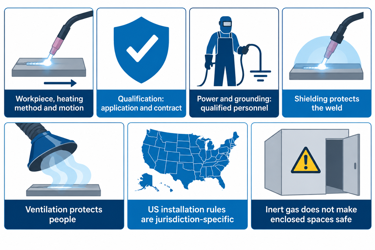
The specification must include the workpiece, the heating method, the mounted load, the motion path and the site services. The selected equipment package must be supported with the appropriate power, cooling and shielding at its intended duty. Qualification is application and contract specific; workplace protections are jurisdiction and operation specific; neither is resolved with the selection of hot-wire.
ISO 15614-7:2016 covers qualification of overlay welding procedures by procedure tests. ISO reviewed and confirmed it in 2022. Its scope distinguishes overlay from build-up/repair and certain buttering applications. Use the project-specified qualification route and dimensional tolerances to judge acceptance for the application.
“ISO 15614-7:2016 specifies how a preliminary welding procedure specification for overlay welding is qualified by welding procedure tests.”
For US general-industry installations, OSHA 29 CFR 1910.254 addresses welding equipment installation, grounding, supply connections and maintenance. Qualified personnel should resolve the supply and protection requirements for the actual equipment. Listed overseas supply voltage isn’t automatically compatible with the plant.
Shielding gas protects the weld puddle while workplace ventilation protects people. Inert gas doesn’t make an enclosed space safe to enter. OSHA 1910.252 requires appropriate ventilation for hazardous contaminants and confined-space oxygen deficiency. Follow the applicable entry and exposure controls.
Send the integrator part drawings, material and filler specification, hardest-access location, target accepted deposit, present cycle breakdown, power/control and other services. Include inspection records and the required deliverables. For cylindrical work, describe the method of part support and turning. The vessel turning-roll selection guide defines that motion.
Frequently asked questions
What is GTAW TIG welding?
GTAW and TIG both mean gas tungsten arc welding. A nonconsumable tungsten electrode supplies the arc, an external gas shield protects the pool, and filler may be added separately.
Hot wire adds filler preheating to that arrangement. It doesn’t turn the tungsten into the consumable wire electrode used in MIG welding.
What is a hot start in welding?
Hot start is a starting function that temporarily changes welding output to help establish the arc. Hot-wire GTAW instead heats the supplied filler during welding through a separate heating arrangement.
The two functions serve different purposes. A machine advertised with hot start still needs a suitable wire heater, feeder and controls to perform hot wire welding.
Does hot wire GTAW work?
Yes. Published trials demonstrate faster filler deposition in configured hot-wire systems, including mechanized cladding and a handheld semi-automatic variant. Production benefit depends on maintaining acceptable weld quality while shortening the complete route.
Use accepted components per shift and total cost as the final measures, with deposition rate as one input rather than the entire result.
Can a standard TIG welder run hot wire?
Yes, as the main arc source within a compatible hot-wire package. The complete system also needs suitable filler heating, feeding, contacts and coordinated controls. The process integrator must establish compatibility; connecting an improvised heater isn’t a safe substitute.
Does hot wire remove the need for shielding gas?
No. Hot-wire GTAW still needs shielding gas to protect the tungsten and molten metal. Preheating the filler changes its melting demand, not its exposure to air.
Keep the gas path, torch assembly and filler clean. Shielding coverage can be lost through poor delivery, access or handling even when nominal flow is unchanged. Work-area ventilation remains a separate requirement from the local shield around the weld; increasing shielding flow doesn’t replace exposure assessment or confined-space precautions.
Define the motion equipment for your hot-wire application
Bring Aubrik the part drawing, mounted-head load, required reach and rotation arrangement, together with the selected process package. Discuss your welding-cell motion requirements so the manipulator, positioner or turning rolls can be scoped around the work. Include the baseline cycle and acceptance requirements to keep the equipment discussion tied to the result you need.
This guide makes use of publicly available technical documents, studies and product information. The experimental figures correspond to their published configurations; the cycles and financial examples depicted herein are based on stated assumptions.
References & Sources
- Ungethüm et al. (2020), Analysis of metal transfer and weld geometry in hot-wire GTAW with indirect resistive heating.
- Spaniol et al. (2020), Development of a novel TIG hot-wire process for wire and arc additive manufacturing.
- Egerland et al. (2015), Advanced Gas Tungsten Arc Weld Surfacing Current Status and Application.
- Newport News Shipbuilding (2013), Evaluation of the Tip Tig Welding System, NSRP final report.
- Henckell et al. (2020), Reduction of Energy Input in Wire Arc Additive Manufacturing with Gas Metal Arc Welding.
- Allford and Hebble (2019), Could GTAW hot-wire go mainstream?, The Fabricator.
- ISO 15614-7:2016, public scope and current status.
- OSHA 29 CFR 1910.254, Arc welding and cutting.
- OSHA 29 CFR 1910.252, General requirements.