Get in Touch with Aubrik Company


Argon arc surfacing refers to depositing metal on an existing surface using an electric arc with argon shielding. The molten area is protected by argon. When setting up the TIG surfacing process, safety questions are related to how the specified gas reaches the torch, covers the working area and is controlled around people.
Argon arc surfacing deposits metal under argon shielding. Check gas identity, delivery and coverage separately from weld quality. Argon can displace oxygen; welding fume and ozone require their own exposure controls.
Quick gas checks
- Confirm the gas against the welding procedure and equipment instructions.
- Trace the delivery path through the connections, hose and torch.
- Check coverage with the workpiece motion and extraction operating as assessed.
- Separate oxygen-deficiency assessment from welding-fume control.
Key points: more gas doesn’t necessarily improve shielding; a flow indication doesn’t prove coverage at the weld pool; a clean-looking bead doesn’t prove a safe breathing atmosphere. The following worksheets assist the manufacturing team in recording these questions prior to a supplier trial.
These sheets were reviewed in September 2026. The author attributes technical notes to their original authors. The examples given for purchasing requests with time estimates are illustrative and shouldn’t be confused with Aubrik test results.
What Does Argon Arc Surfacing Mean?

Argon arc surfacing describes depositing a metal layer with argon shielding, but the phrase alone doesn’t fully describe the welding process. This manual is concerned with gas shielding for TIG surfacing. First, determine the process. Once the process is understood, identify the gas, working conditions and the equipment that’s required to transport it and protect the weld around the workspace.
In Tungsten inert gas welding, a non-consumable tungsten electrode strikes the arc, and the welding wire or other filler is added when needed. Gas tungsten arc welding is another term for TIG. The electrode isn’t expected to melt into the deposit.
Using argon helps lessen the interaction between the molten weld pool and air. This is relevant to oxidation and gas absorption. This also doesn’t define the completed coating’s wear resistance, corrosion resistance or any other mechanical property. These properties depend on the identified substrate, filler alloy and applicable procedure. Gas checks support this work; they don’t replace it.
A terminology trap: an order for an “argon welding machine” leaves too much unresolved. Argon arc welding is used informally for TIG, while argon-containing mixtures also appear in other welding applications. Conventional shielded metal arc welding, or SMAW, uses a flux-covered consumable electrode. Describe the welding method by its designated name when ordering the gas equipment.
In order to outsource a job, the welding trial brief and gas requirements should mention the parent material and the task to be performed. “Use argon” only includes part of the brief.
Specify the Shielding Gas Separately From the Process

Instead of treating every cylinder labeled argon as interchangeable, specify the shielding gas by the approved procedure and equipment requirements. Record its name, required composition and the applicable quality records associated with it. Even with a label on the cylinder, the delivery path can be contaminated or poorly sealed. This affects the protection of the arc.
TWI identifies argon, helium and certain mixtures in TIG applications. Mixture suitability depends on the material and application. An industrial buyer should therefore avoid copying a gas choice from an unrelated aluminum, carbon-steel or stainless-steel job. TIG also serves refractory metals, but that doesn’t make one shielding arrangement suitable for every metal.
The gas specification and delivery record
- Identify the gas designation, cylinder or supply and supplier documentation.
- Attach the procedure’s gas composition or purity requirement and its source.
- Check regulator, flow-measuring device, hose and torch requirements against their manufacturers’ instructions.
- Record the connections, routing and settings used for the trial.
Illustrative purchasing situation: In one example, a fabrication shop receives a replacement cylinder before a surfacing trial. The buyer sees “argon” on the delivery documentation and assumes the setup can continue. However, the welder then does a cross-check against the procedure and notes that the gas mixture wasn’t documented in the previous trial. The next best course of action is to resolve the missing specification with the responsible welding engineer and gas supplier. It isn’t to determine the mixture from the appearance of the bead or a neighboring MIG station. Purchasing documents the controlling document for future substitutions. This example establishes no gas recipe.
When selecting gas, there are many other considerations. Don’t expect uniform penetration, a particular thickness or less deformation just because a cylinder contains a named gas. For industrial applications, these outcomes need empirical evidence based on the base metal, filler, procedure and process parameter settings.
Trace Shielding Problems From Cylinder to Weld Pool

Diagnose shielding problems along the entire gas path instead of just increasing gas flow. Other issues like leaks, drafts, and excessive flow can lead to porosity as can moisture and contamination on the material. The better approach is to preserve the current setup before changes obscure it and assess possible causes separately from the evidence you’re recording.
TWI’s porosity guidance outlines multiple gas protection and contamination mechanisms. A lesson learned is that a porous deposit isn’t a unique diagnosis. The worksheet as presented isn’t applicable as an approved maintenance instruction. This diagram is an editorial worksheet.
9-Point Shielding Fault Map
| Location | Question to investigate | Evidence to preserve | Limitations / Not suitable for |
|---|---|---|---|
| Supply identity | Does the supplied gas match the procedure? | Designation and delivery record | Correct identity does not prove downstream cleanliness |
| Regulation equipment | Is the installed device appropriate and serviceable? | Model, condition and manufacturer checks | A dial reading does not establish gas quality |
| Flow indication | Was delivery checked under the relevant operating condition? | Method, configuration and recorded indication | More indicated flow does not guarantee better coverage |
| Connections | Could a connection be leaking? | Approved leak-check result and location | Use the equipment instructions; this table gives no repair method |
| Hose route | Does movement strain or damage the route? | Inspection notes through the planned movement | A stationary check misses changing geometry |
| Torch and gas cup | Does the fitted configuration match the procedure? | Part identity, condition and setup record | No universal cup or electrode-extension prescription |
| Workpiece area | Is a draught or other disturbance affecting coverage? | Door, fan and extraction conditions during the fault | Do not disable required ventilation to protect a bead |
| Surface and filler | Could moisture, oil or another contaminant be involved? | Material, cleaning and storage records | Use material-specific cleaning instructions |
| Stop and restart | What changed between acceptable and affected runs? | Time, motion position and restart records | Correlation does not establish a single root cause |
A common misdiagnosis: Many defects are incorrectly attributed solely to inadequate quantities of argon. TWI mentions the potential for pore formation from oil, grease and moisture. A crack, lack of fusion or an unexpected surface condition requires a separate assessment; this gas-path map cannot authorize the release of a weldment to service.
Keep the symptom separate from the cause. Record what changed, use approved inspection methods, and have the responsible person decide whether the evidence justifies restarting.
Protect Bores and Enclosures From Oxygen Displacement

Argon can displace oxygen and create an asphyxiation hazard in cases of gas buildup. An assessment of the actual geometry and gas release is needed for a given enclosed space, bore, pit or vessel. The absence of smoke, odor, or an active arc doesn’t ensure a safe atmosphere to enter.
The UK Health and Safety Executive’s asphyxiation guidance addresses shielding gases and oxygen deficiency. It supports avoiding entry where possible and planning the necessary atmospheric checks, ventilation and rescue arrangements. These are distinct from deciding whether the weld itself received sufficient shielding.
For the US site, a competent safety professional must assess the site and identify the applicable site and confined-space requirements. Neither a gas supplier’s purity certificate nor a successful weld coupon establishes compliance with site requirements. Installing a local fume hood doesn’t demonstrate that oxygen is sufficient in an enclosure or in all positions that a person could occupy.
Illustrative bore-access situation: a team plans to inspect an internal surfacing pass after the torch stops. The workpiece is open at one end, so someone assumes that stopping the arc has removed the concern. The supervisor considers the proposed access to be a separate activity. All aspects of the gas-release path, enclosure geometry, the existing assessment, and authorized entry arrangements must be checked before anyone can enter. Remotely inspecting the pass (if that is possible) is the first option the team will consider. The example doesn’t prescribe a waiting time or a gas-monitor location. Both would need to come from the actual risk assessment, not from the visible shape of the opening.
Critical boundary: don’t enter a potentially oxygen-deficient space to investigate a leak or attempt an improvised rescue. Isolate the area and follow the site’s trained emergency arrangements. A particulate respirator doesn’t supply missing oxygen.
Assess Welding Fume and Ozone Separately

Assess the impacts of welding fume and ozone independently of argon’s oxygen displacement hazard. The process, the parent metal, the consumables and the work pattern affect exposure. A TIG setup may necessitate controls, even with a small visible plume. Protect the nearby workers and the welder, and verify that the selected controls are effective under actual conditions.
OSHA’s welding fume fact sheet includes metal fume and gases associated with arc welding. Hexavalent chromium may be a hazard with welding of chromium containing materials. Working outdoors alone doesn’t ensure adequate ventilation. A process that’s perceived to be cleaner doesn’t measure exposure.
“The most effective way to reduce welding fume is to capture it at source”
Two-Hazard Air-Control Split
- For oxygen deficiency, assess gas release, accumulation, access and the atmosphere people could enter.
- For fume and welding gases, identify material and process hazards, capture emissions where practicable and assess remaining exposure.
- Select respiratory protection for the assessed hazards; particulate filters don’t protect against welding gases or supply oxygen.
- Retain evidence that the installed controls work for the actual task and protect others nearby.
A misleading shortcut: moving the operator away from a mechanized torch and declaring the area controlled. HSE’s exposure-reduction guidance addresses mechanization in the context of the other controls. It doesn’t mean that exposure will automatically be reduced and controlled. TIG-related ozone and nearby personnel must also be considered.
UK guidance here explains control principles. It isn’t a substitute for the applicable requirements at a US installation regarding exposure assessment and respiratory protection. Selecting a filter from a general article on welding technology shouldn’t be undertaken.
Check Shielding Coverage While the Workpiece Moves

Consider the movement of the workpiece and not just the initial torch position when assessing the supply and removal of gas. Hose routing, access and the proximity of the source to the extraction hood will affect layout. A dry run may be useful to plan the layout. However, it can’t prove weld quality or exposure control during the live process.
According to HSE’s movable-extraction guidance, positioning the hood correctly is an important aspect of effective capture. Also, extracted workstations may contain turntables. The integration challenge is how the work stays inside an effective capture arrangement while maintaining the shielding required by the welding procedure.
An example that illustrates a rotating-part situation is as follows: we commence this example with the hose clear of the fixture, and the extraction hood in proximity to the work area. Later in the rotation the hose route becomes increasingly tight and the working area moves away from the capture position. The positions are recorded by the team during a controlled dry run. The welding and ventilation specialists are asked to agree to the arrangement for the live procedure. In this example the team doesn’t move the hood farther away to make the bead look better. The record captures the positions, and shows who verifies each control. This record doesn’t transform the dry run into evidence of safe live exposure.
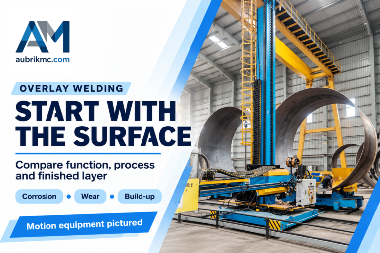
Aubrik publishes workpiece rotation equipment and torch positioning equipment , which can be considered part of a moving work piece or moving torch family of equipment. The presence of this equipment doesn’t confirm that the gas train, extraction system or surfacing method has been qualified as a complete system.
Keep motion evidence restricted: record the routing of the gas line, the position, and the width of the working area. The questions of deposition rate, structural load capacity or final layer of the build should be considered part of the process and equipment evaluation.
Compare Gas-Related Downtime With a Filled Example

To compare gas-related interruptions, record preliminary checks, fault stoppages and restart work separately. Separate time records must be kept for gas-related stoppages. Recorded time sheets allow you to identify what you need to measure; however, a recorded time assumption that captures a potential reduction isn’t evidence of a productivity advantage. A job change shouldn’t be considered time saving unless it’s backed up by comparable jobs and documented acceptance.
9-Stage Gas Interruption Example
Illustrative inputs only: Sets A and B each produce one accepted part under the same acceptance requirements. The stages are sequential, without overlap or queue time. Every time below is invented to demonstrate accounting; none is an Aubrik measurement, welding setting or predicted saving.
| Recorded stage | Set A | Set B |
|---|---|---|
| Cylinder verification | 3 min | 3 min |
| Gas-path inspection | 4 min | 7 min |
| Surface and wire check | 5 min | 5 min |
| Shielding and extraction setup | 4 min | 6 min |
| Dry run | 5 min | 7 min |
| Arc-on deposition | 30 min | 30 min |
| Gas-fault stoppages | 12 min | 2 min |
| Restart checks | 8 min | 3 min |
| Inspection and records | 6 min | 6 min |
| Total | 77 min | 69 min |
Set B decreases the assumed stoppage and restart entries by 15 min and increases the time needed for the preliminary work by 7 min. This nets an illustrative time difference of 8 min total (77 min minus 69 min). The time for the arc remains consistent at 30 min in both sets. The mitigation in time for the assumed stoppage and restart is recorded as a method for capturing assumed savings; it doesn’t establish savings due to additional checks or any other factor.
The hidden bottleneck: If a shop records only arc time, both sets appear the same. Finance needs the complete gas interruption record, and quality staff need evidence that a restart occurred without bypassing inspection. Before the plant manager considers this a process efficiency improvement, both need to be satisfied.
TWI’s list of possible porosity causes suggests investigating the mechanism rather than attributing each stoppage to low flow. Replace example values with actual records before claiming a productivity improvement. If work overlaps or a second layer introduces other conditions, define a new accounting boundary rather than reusing the same totals.
Bring a Gas and Extraction Brief to the Supplier

Bring the supplier a gas-and-extraction brief that identifies the setup, unresolved questions, and the people charged with addressing those questions. Keep the gas delivery, weld acceptance and worker protection as separate approvals. A signed equipment quotation or gas certificate can’t replace all three, especially when several contractors share the installation.
Pre-Arc Gas Record: 9 Handoff Fields
This example, filled in for a rotating steel component, describes requested records (not approved materials, not operating settings, not a completed safety assessment). Adjust the responsibilities to the actual contract.
| Field | Filled request | Proposed owner | Limitations / Not suitable for |
|---|---|---|---|
| Process identity | TIG surfacing; identify the controlling procedure | Welding engineer | No approval implied by the process name |
| Material record | Supply parent and filler identification | Buyer and welding engineer | “Steel” alone is insufficient |
| Gas requirement | Attach specified composition and quality documentation | Welding engineer and gas supplier | No universal purity value supplied here |
| Delivery equipment | Identify regulation, measurement, hose and torch components | System integrator | Component identity is not a successful system test |
| Gas-path checks | Record the approved inspection and leak-check method | Authorized maintenance personnel | This worksheet is not a repair instruction |
| Movement record | Document relevant hose and workpiece positions | Integrator and trial team | A dry run does not establish live exposure |
| Oxygen-deficiency assessment | Resolve enclosure access and atmospheric-control requirements | Competent site safety personnel | A fume hood alone does not close this item |
| Fume and gas exposure | Verify capture and remaining exposure for the task | Exposure-control specialist | Particulate filters do not cover every hazard |
| Restart authority | Name who closes each unresolved fault before resuming | Buyer, welding lead and site safety lead | No automatic release from a clean-looking bead |
A contract gap to catch: each of the three vendors (gas supplier, motion-equipment vendor, ventilation contractor) may supply a contractual component of the system without owning the combined system trial. To avoid this, the integration responsibility should be made explicit. Use ISO’s public scope for overlay procedure qualification to determine that a gas check is not a complete welding qualification. The remaining qualification route still requires a competent review.
Before requesting a trial: gather the material identities, procedure reference, gas requirement, delivery layout, workpiece movement and separate exposure-control responsibilities. Mark missing items as unresolved.
For the broader purchase discussion, Aubrik’s supplier readiness checklist invokes additional questions regarding inspection, electrical requirements and spare parts. Keep the gas-specific worksheet with those commercial records.
Send those records with your gas-path and extraction inquiry to Aubrik. This gives the supplier concrete integration questions to answer without suggesting that a general product listing satisfies your surfacing and safety requirements.
Frequently Asked Questions
What is the argon arc process? It is an informal description that needs a specific process designation.
The phrase commonly refers to arc welding under argon shielding. In TIG, a tungsten electrode supplies the arc and filler can be added separately. Surfacing deposits material on a substrate rather than primarily making a joint between parts. Confirm the actual process, materials and gas specification before treating the informal name as an equipment or procedure requirement.
What is the purpose of argon in argon arc welding? It shields the working region from the surrounding air.
Argon is used to protect the molten region from atmospheric exposure during suitable arc-welding applications. That shielding role is among the principal benefits of argon. Gas identity alone doesn’t show that protection reaches the weld pool: delivery integrity, torch configuration and local conditions also matter. The finished deposit still needs the acceptance evidence required by its application.
What is porosity and how can it be prevented? Gas trapped during solidification leaves pores; prevention depends on the cause.
Porosity consists of gas cavities left as weld metal solidifies. TWI identifies poor shielding, leaks, excessive flow, draughts and contamination among possible causes. Investigate the gas path and material preparation using the relevant instructions, rather than assuming the cure is more argon. Inspection must establish what defect is present; the appearance alone doesn’t reliably identify the source.
What argon flow rate should be used for surfacing? Use the requirement for the qualified setup.
No universal flow rate is suitable for every torch, geometry and environment. Follow the applicable procedure and equipment instructions; excessive flow can also disturb shielding.
Does a welding respirator solve an argon leak? A particulate respirator does not supply oxygen.
No. Address the release and atmosphere through the site’s assessed controls and emergency arrangements. Particulate filters also don’t protect against welding gases.
Is argon welding dangerous? Its hazards require task-specific controls.
Argon can displace oxygen; arc welding can generate hazardous fume and gases. Electrical, radiation and high-temperature hazards also remain. A low-smoke process isn’t automatically safe.
References & Sources
- TWI: TIG process characteristics and shielding gases.
- TWI: porosity causes and prevention.
- HSE: asphyxiation hazards in welding.
- HSE: welding-fume controls.
- HSE: avoiding and reducing exposure.
- OSHA: controlling hazardous fume and gases during welding.
- ISO 15614-7:2016: public scope of overlay procedure qualification.
TWI provides the referenced process and porosity guidance; OSHA and HSE provide the referenced information on hazard control. The diagnostic map, handoff record and time example are editorial tools. They aren’t welding procedures, ventilation designs or supplier performance certifications.