Get in Touch with Aubrik Company

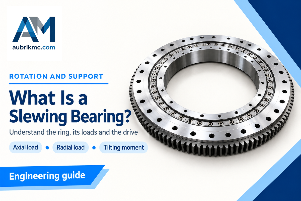
What is a slewing bearing? A slewing bearing is a ring-shaped bearing that allows relative rotation between two structures while carrying axial loads, radial loads and overturning moments. It’s frequently referred to as a slewing ring or turntable bearing and provides a compact connection between a fixed base and a rotating assembly.
A large opening through the center of the bearing can leave space for cables, pipes or a shaft. Gear teeth may be machined into either ring, but a geared bearing still needs a drive to turn it.
A slewing bearing supports a rotating structure through a ring-shaped joint. Its load case includes axial force, radial force and tilting moment. Gear teeth transmit drive torque when the ring has a geared design.
Quick reference: Main parts: inner ring, outer ring and rolling elements. Load directions: axial, radial and tilting. Common constructions: four-point ball, double-row ball, crossed roller and three-row roller. Gear choices: internal, external or toothless.
What is a slewing bearing?
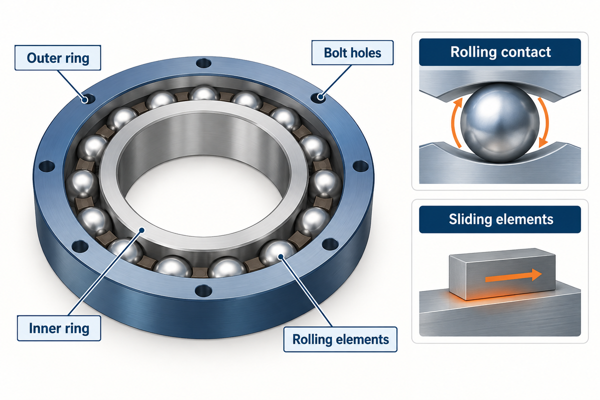
A slewing bearing connects two mounting structures through concentric rings that can rotate relative to each other. In a rolling element bearing design, the load is carried by balls or rollers, which are confined to the inner and outer rings by means of raceways. Bolt holes connect each ring to its respective structure, which becomes part of the load path.
The bearing is similar to the one supporting the base of a rotating machine platform. The platform turns while the base stays still. A slew ring bearing performs that support function, often across a much larger diameter than a shaft bearing. However, size doesn’t always define the category.
A rotational rolling-element bearing allows relative rotation between structures through rolling contact. Another design uses polymer sliding elements between the rings. A simple plain ring and a ball slewing bearing achieve relative rotation using different contact and friction mechanisms.
How does a slewing bearing work?
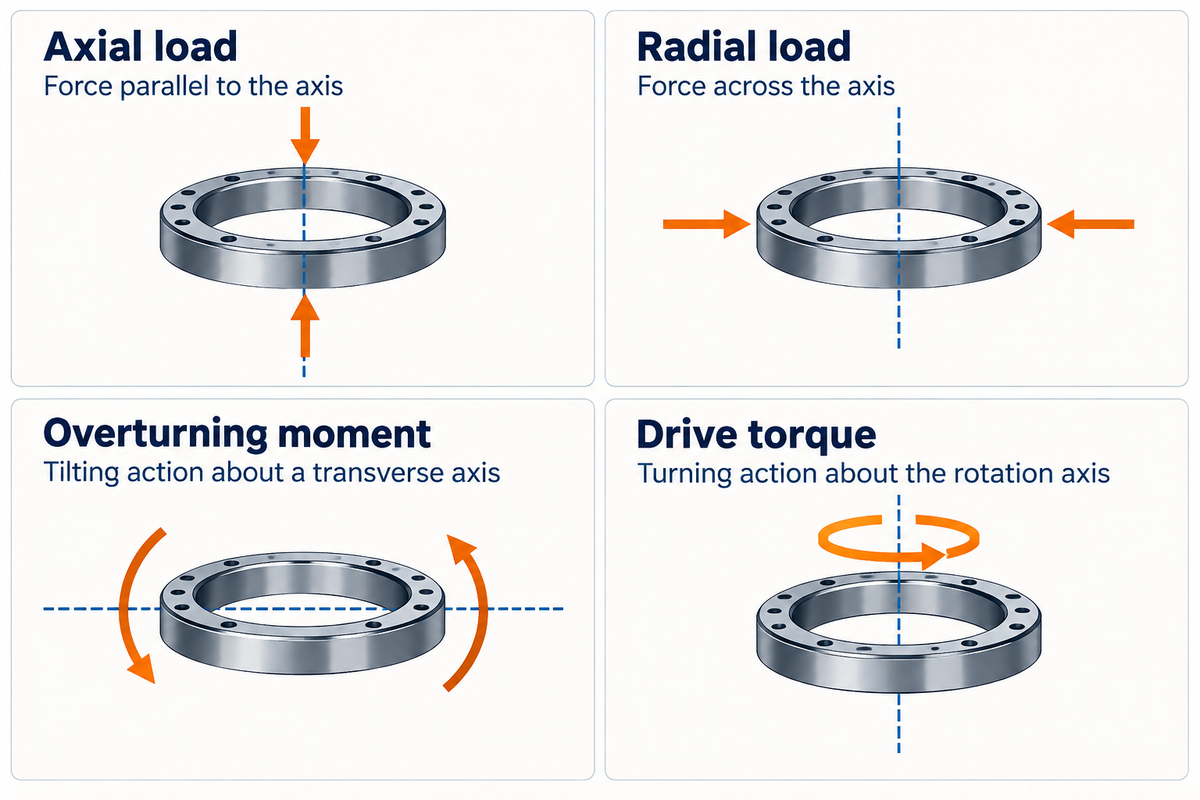
Loads are passed from one mounting structure to the next via rolling contacts and a bearing ring. Contact geometry allows for free rotation and handles loading along and across the axis of rotation. An off-center force also produces a tilting moment; these moment loads change the loading around the ring.
Keller and Guo describe the pitch-bearing connection as “allowing relative rotation of the blade with respect to the hub.”
Steel balls or rollers run on hardened raceways; spacers keep rolling elements separated. Seals retain lubricant, and keep out contamination. Bearing design and material selection determine the behavior of those contacts. Alloy steel rings alone don’t denote the capacity of the assembled joint.
Use the 3-Load Sketch
Axial means parallel to the rotation axis; radial means perpendicular. These directions rotate with the installation; therefore axial doesn’t always mean vertical. Build the sketch in the following order.
- Draw the axis. Mark which structure stays fixed and which rotates.
- Add the forces. Mark each application point and its axial or radial direction.
- Show the offsets. Locate the center of gravity and mark tilting separately from the drive torque.
| Load or action | Mark on the sketch | Information it supplies |
|---|---|---|
| Axial load | Force parallel to the axis | Direction and magnitude of thrust |
| Radial load | Force across the axis | Side load on the rings |
| Overturning moment | Tilting action about a transverse axis | Effect of load offset |
| Drive torque | Turning action about the rotation axis | Demand on the drive and gear |
Consider a long workpiece supported by a welding fixture. With the workpiece centered over a horizontal turntable, its weight acts mainly along the rotation axis. A clamp or process force can add a radial load as well. A useful sketch shows the center of gravity, the force application points, the full rotation envelope, the tilting moment, and the torque necessary to turn the fixture.
Types of slewing bearings and gear arrangements
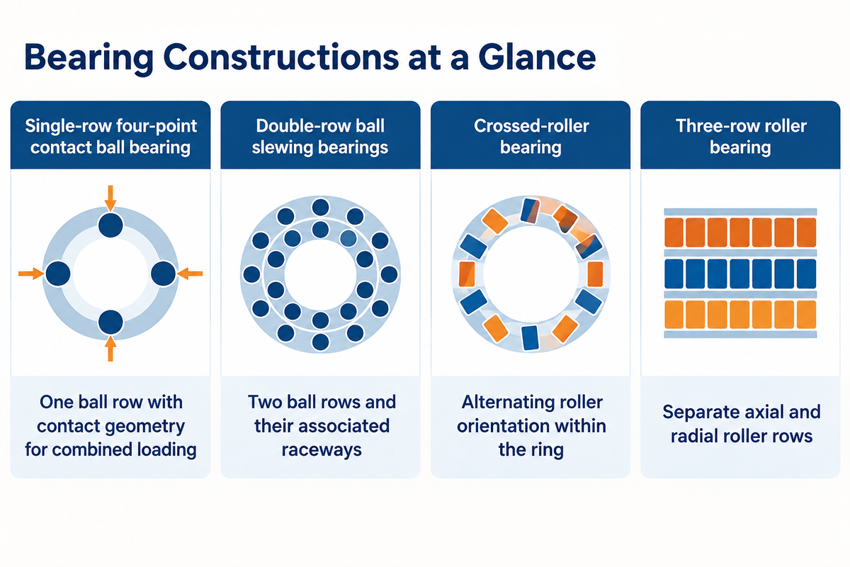
Single-row four-point bearings are slewing ring bearings that use balls; crossed-roller designs alternate roller orientation; and three-row roller designs separate load-carrying functions. Internal teeth, external teeth and toothless rings are gear choices distinct from bearing construction, so the construction type and gear choice belong on the same specification.
Kania, Krynke and Mazanek’s catalogue-capacity study compares four principal constructions. Construction, gear position and assembly scope are shown separately below.
| Choice axis | Type | What changes |
|---|---|---|
| Construction | Single-row four-point contact ball bearing | One ball row with contact geometry for combined loading |
| Construction | Double-row ball slewing bearings | Two ball rows and their associated raceways |
| Construction | Crossed-roller bearing | Alternating roller orientation within the ring |
| Construction | Three-row roller bearing | Separate axial and radial roller rows |
| Gear position | External gear | Pinion engages teeth outside the ring |
| Gear position | Internal gear | Pinion engages teeth inside the ring |
| Gear position | Toothless ring | Drive acts through another part of the assembly |
| Contact mechanism | Plain slewing ring | Sliding elements replace balls or rollers |
| Assembly scope | Slew drive | Gearing and housing form an assembly around the bearing |
How do three rows of rollers distribute loads?
Three-row roller slewing bearings employ separate roller rows for axial and radial loading. Two axial rows resist loads in opposite directions and contribute to overturning-moment resistance; the third row carries radial load. Rather than each contact performing the same function, this construction employs different contacts to perform different functions.
Rows of rollers describe the construction; ring deformation, support stiffness and applied forces determine the actual load distribution. The same capacity study takes the rings, supports and coupling elements into account, as well.
Slewing bearing vs ball bearing and slew drive
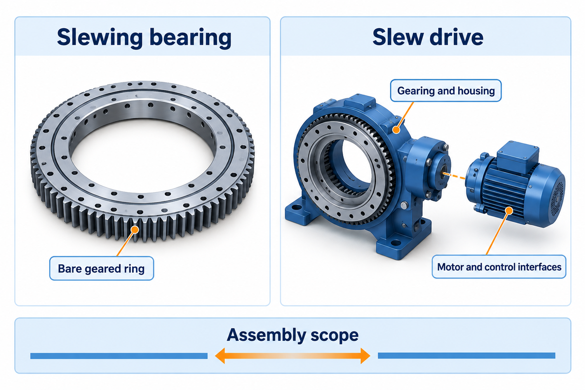
A ball bearing is determined by its rolling elements, and a slewing bearing is determined by its arrangement and rotational duty. A lot of slewing rings contain balls, which explains the overlap in the above mentioned categories. A slew drive adds a mechanism for producing rotation, typically with a housing and gearing, while the supplied motor and other accessories vary by assembly.
Standard bearings mounted on a shaft may support a rotating platform through a different bearing arrangement. A slewing ring places the support around a wide opening and can be attached directly to both structures. Shaft-mounted single-row ball bearings and roller bearings need their own supports. Compare that installation to the directly supported slewing ring.
What are some alternatives to slewing bearings?
Paired shaft bearings can support rotation when the machine has room for a shaft and its supports. Tapered roller bearings are designed for combined radial and axial loading; NSK describes opposed pairs and double-row arrangements for this. Plain slewing rings offer sliding rotation instead of rolling contact. The arrangements supported by these bearings constrain the position and require a supporting structure.
Suppose a buyer wants to replace a positioner with a motor, reducer and exposed pinion. A quote for a bare geared ring could be within the buying scope. A second quote with the heading “slew drive” could provide a housing and worm gear that alters the mounting interface entirely. The buyer should consider what connects to the base, what connects to the fixture, as well as what connects the motor to the mechanism. If the original pinion stays, its tooth geometry belongs in the enquiry; for a fully new drive, the motor and control interfaces would also be pertinent. An article on slew drives for welding positioners outlines assembly choices.
Where are slewing bearings used?
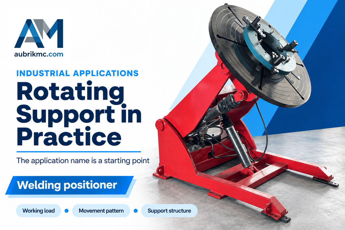
Slewing bearings support rotating mechanisms in excavators, cranes, wind turbines and industrial turntables. In general, their task is to connect a moving element of an assembly to a supporting element while carrying a working load. Each machine has a different load history and movement. Therefore, an application name is only a starting point for bearing selection.
- Excavators rotate their upper structure relative to the undercarriage.
- Crane slewing connections carry loads from the rotating structure and its working reach.
- Wind turbine yaw bearings orient the nacelle, while pitch bearings allow blade-angle adjustment.
- In material handling and other industrial applications, platforms turn parts through a process or loading position.
NREL’s 1.5 MW reference-turbine study focused specifically on pitch-bearing loading. In fabrication, welding turntables and rotary welding positioners illustrate how the support and drive work together. Renewable energy and heavy machinery share the need for rotational support, but their duty cycles differ.
How do you choose a slewing bearing?
Select a slewing bearing using the simultaneous axial force, radial force and overturning moment, including the moment caused by an offset load. In conjunction with these load cases, the stiffness of the support and the bolted connection need to match the rating assumptions. The envelope dimensions need to be evaluated to ensure physical fit.
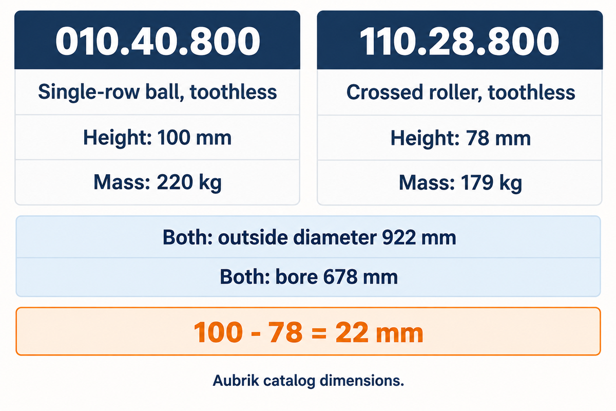
A comparison of models in the published Aubrik slewing bearing dimensions reveals similarity in bore and outside diameter and differences in height and weight. Model 110.28.800 is a toothless cross-roller bearing.
| Catalog model | Construction | Outside diameter | Bore | Height | Mass |
|---|---|---|---|---|---|
| 010.40.800 | Single-row ball, toothless | 922 mm | 678 mm | 100 mm | 220 kg |
| 110.28.800 | Crossed roller, toothless | 922 mm | 678 mm | 78 mm | 179 kg |
The catalog heights differ by 100 − 78 = 22 mm. That difference moves the supported assembly and can change neighboring clearances. Compare the load rating and full mounting drawing with the dimensions provided in Aubrik’s public catalogue.
How thick should the mounting plate be for a slewing bearing?
The proposed design assumptions and load cases for a slewing bearing must be assessed together with its mounting plate and supports. Size the mounting plate together with its ribs, unsupported spans, bolt locations and applied loads to provide the stiffness assumed in the bearing’s load assessment.
He and colleagues’ integrated bearing-support study models rings, rolling elements, bolts and surrounding structures together. Silverthin’s mounting guidance also considers the mounting surface and the type of fastening as part of bearing performance. For heavy-duty applications, send the support drawing with the load case rather than treating plate thickness as an isolated catalog value.
How much does a slewing bearing cost?
The compact plain igus PRT-01-20 ring was listed at US$216.33 per piece, excluding freight, on its US product page checked on November 3, 2026. Slewing bearing cost depends on diameter, bearing construction, required precision, gear machining and supply scope; this quoted product is a small sliding ring.
Its outside diameter is 3.15 in, approximately 80 mm, and it uses an aluminum housing with polymer sliding elements. When comparing quotes for the same drawing and included components, choose between slewing bearing manufacturers. A steel rolling element assembly also requires a quote for its own specification.
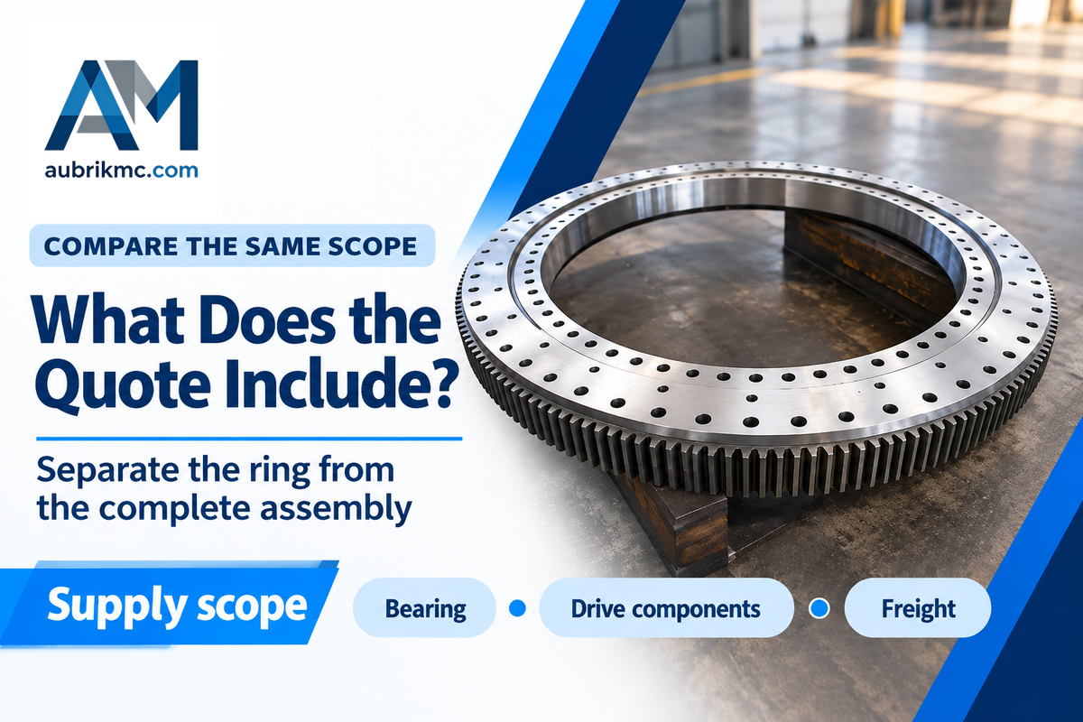
Consider the purchasing team receiving two quotes for an industrial turntable. One supplier includes the bearing, the matching pinion, and inspection docs, while the other quote just has a toothless ring. Comparing their totals would combine a component-price difference with a scope difference. The team can break each quote into the ring, drive components, documentation, freight and any mounting work, then ask for the missing items. A cheaper bare ring might still be useful with a drive that’s being retained. A complete assembly might suit a new build. Procurement can then ask each supplier to provide a price for the missing pinion, identify the mounting drawing revision and say whether freight is included.
How long does a slewing bearing last?
Slewing bearings have no universal service-life duration. Fatigue and wear in service, lubrication, contamination and the behavior of the mounting structure have to be taken into consideration. For industrial machinery that repeatedly moves through small angles, the motion pattern deserves as much attention as the peak load.
ISO 16281:2025 covers modified reference rating life for universally loaded rolling bearings, including effects such as lubrication, contamination, tilt and internal load distribution. Its stated scope excludes wear and microspalling. The edition was published in January 2025, with a corrected version in August 2025; it is a calculation standard, not a product certificate.
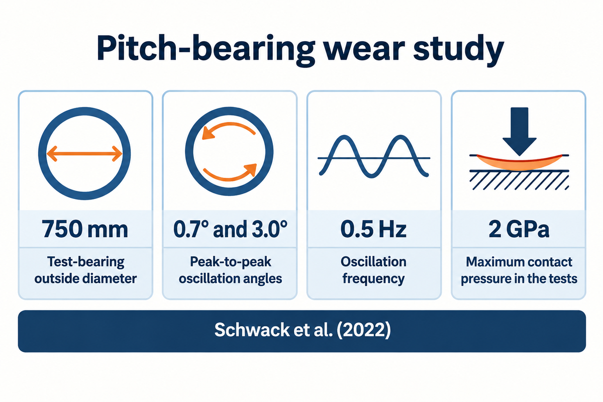
Schwack and colleagues assessed oscillatory wear of pitch bearing designs. Include movement amplitude in the assessment of oscillatory wear.
750 mmTest-bearing outside diameter
0.7° and 3.0°Peak-to-peak oscillation angles
0.5 HzOscillation frequency
2 GPaMaximum contact pressure in the tests
Premature bearing failure can involve the surrounding joint as well as the rolling contacts. Keep inspection reports and operating history together so a change in play, noise or lubricant condition can be investigated. The slewing bearing maintenance guide addresses the maintenance aspect more thoroughly.
What should you send with a slewing bearing enquiry?
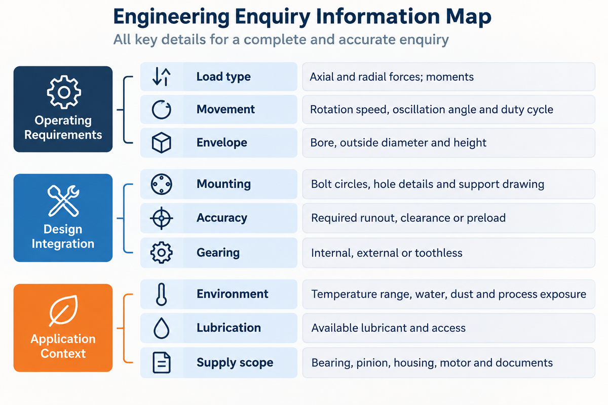
A good slewing bearing enquiry combines the load case, movement pattern and interface sketch in the same package. State your preference between a bare bearing or a driven assembly. Then identify the dimensions and operating conditions the supplier must assess.
Fill these fields in your request. Provide the intended machine’s loads and operating values with units so the bearing can be assessed for that duty.
| Parameter | Information to provide | Why it matters | Confirmation to request |
|---|---|---|---|
| Load type | Axial and radial forces in N or kN; moments in N·m or kN·m | Defines simultaneous loading | Combined-load assessment for the stated case |
| Movement | Rotation speed, oscillation angle and duty cycle | Separates continuous rotation from repeated short movements | Duty assumptions used in selection |
| Envelope | Bore, outside diameter and height in mm | Sets available space | Dimensioned drawing and revision |
| Mounting | Bolt circles, hole details and support drawing | Controls joint geometry and stiffness | Mounting requirements for that structure |
| Accuracy | Required runout, clearance or preload | Controls positioning behavior | Inspection method and acceptance values |
| Gearing | Internal, external or toothless; mating-drive details | Defines the drive interface | Matching tooth geometry and backlash requirements |
| Environment | Temperature range, water, dust and process exposure | Guides seals and material selection | Applicable sealing and protection provisions |
| Lubrication | Available lubricant and access to lubrication points | Connects the component to the maintenance system | Product-specific lubrication instructions |
| Supply scope | Bearing, pinion, housing, motor and documents required | Makes quotations comparable | Itemized inclusions and exclusions |
When requesting a replacement, give the part number and show both mounting faces. When identifying a used slewing bearing, include the fixed ring arrangement and mating gear as well as ring dimensions.
Frequently Asked Questions
What are the dimensions of a bearing?
The main bearing dimensions are bore, outside diameter and overall height. Aubrik model 010.20.200 has a 120 mm bore, 280 mm outside diameter and 60 mm height.
For a slewing ring, also record bolt-circle diameters, hole sizes, threaded-hole details and any gear dimensions. The mounting drawing identifies which features belong to each ring. Include its revision when ordering a replacement, because replacement suitability requires a matching mounting interface and adequate load capacity as well as a matching outside diameter.
What is a slew bearing on an excavator?
An excavator slew bearing connects the rotating upper structure to the undercarriage.
The ring supports machine and working loads while allowing the upper structure to swing. In a geared arrangement, the swing drive engages the ring gear to produce rotation. The bearing, hydraulic motor and gearbox perform different functions, so replacement identification should use the machine model and the component’s actual part number.
What is a slewing gear?
A slewing gear transmits torque to turn a structure about its slewing axis.
In many machines, a pinion engages teeth on the inner or outer ring of a slewing bearing. The gear transmits drive torque while the bearing carries structural loads. Gear tooth form, size and backlash belong in the drive specification alongside lubrication and the connection to the motor or gearbox assembly.
What is the purpose of a swivel bearing?
A swivel bearing allows connected parts to turn relative to one another while carrying load. The term covers several designs rather than one standard slewing-ring construction. Identify the required movement, mounting arrangement and load directions before comparing products described by that name.
How often should I check slewing bearing bolt torque?
Check slewing bearing bolt torque after commissioning and during service at the intervals specified for the machine and its bearing joint, using the specified tightening procedure.
That procedure should cover checks after commissioning and during service, including the stated fastener and lubrication conditions. Record the inspection results so changes can be traced. If the assembly develops unusual movement or noise, investigate the bearing and support joint; applying more torque doesn’t identify the cause. Bolt torque values belong to the approved joint specification.
Can I use thread-locking compound on slewing bearing bolts?
Use thread-locking compound only when the specified assembly procedure includes it. The tightening method relies on defined friction conditions. Match the compound, fastener coating and lubrication condition to that procedure so an unplanned change doesn’t alter the intended bolt preload.
What is the difference between slewing and non-slewing cranes?
A slewing crane can rotate its upper structure or boom about a slewing axis; a non-slewing crane lacks that motion in its normal configuration.
The distinction describes machine movement. It doesn’t identify one universal bearing construction or determine lifting capacity. For replacement components, use the machine model and parts documentation. The crane’s own load chart and operating instructions define its permitted working configurations and loads.
References & Sources
- Keller, J., and Guo, Y. (2022). Rating of a Pitch Bearing for a 1.5-Megawatt Wind Turbine. NREL report, OSTI record.
- Kania, L., Krynke, M., and Mazanek, E. (2012). A catalogue capacity of slewing bearings. Mechanism and Machine Theory, 58, 29–45.
- Schwack, F., et al. (2022). Wear in wind turbine pitch bearings, A comparative design study. Wind Energy, 25, 700–718.
- He, et al. (2024). Study on … Four-Point Contact Ball Slewing Bearings Based on a Bearing Support Bolt-Integrated Model. Machines, 12(11), 814.
- International Organization for Standardization. ISO 16281:2025 public scope and publication details.
Discuss your bearing application
Send Aubrik your load sketch and mounting drawing, and state your desired supply scope, to initiate a slewing bearing enquiry. When requesting a replacement, provide the existing model and gear details. These inputs aid in moving discussion from a general bearing type to a specific interface and operating duty.