Get in Touch with Aubrik Company

Welding Manipulators (Column & Boom): 11-Point Guide

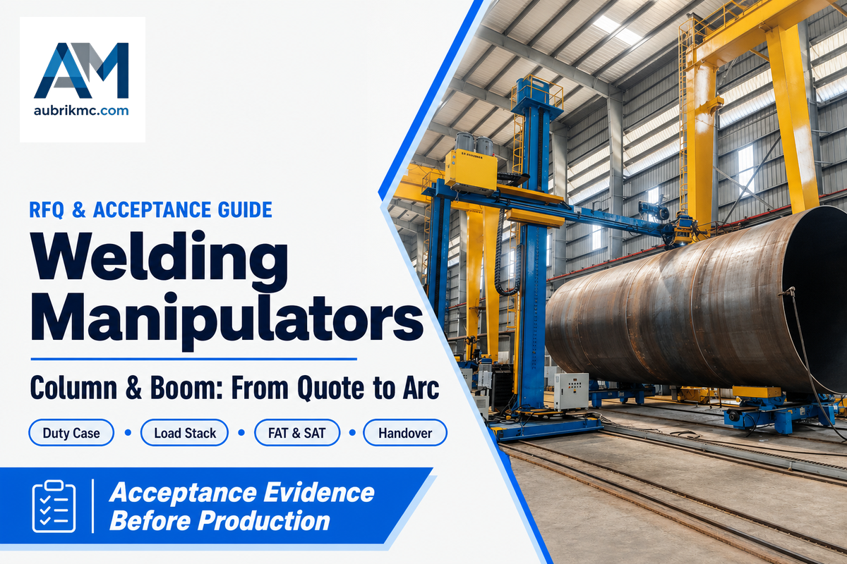
A welding manipulator can look complete on a quotation and still arrive with unanswered questions about load, signals, utilities, guarding, factory tests, and final release. This guide is for the people who must close those questions: fabrication and production engineers, welding coordinators, project managers, maintenance leaders, EHS teams, and procurement staff.
If you first need the equipment basics, read how column-and-boom manipulators work. Here, the job starts later. We’ll turn a production duty into comparable supplier responses and witnessed evidence, without inventing a universal payload, deflection tolerance, safety level, or productivity claim.
Bottom line: accept the documented condition, not the model label. Freeze the load and interfaces, assign every boundary, witness the promised test, retest installation changes, and close the record set before production release.
Quick Specs: What the Acceptance File Must Control
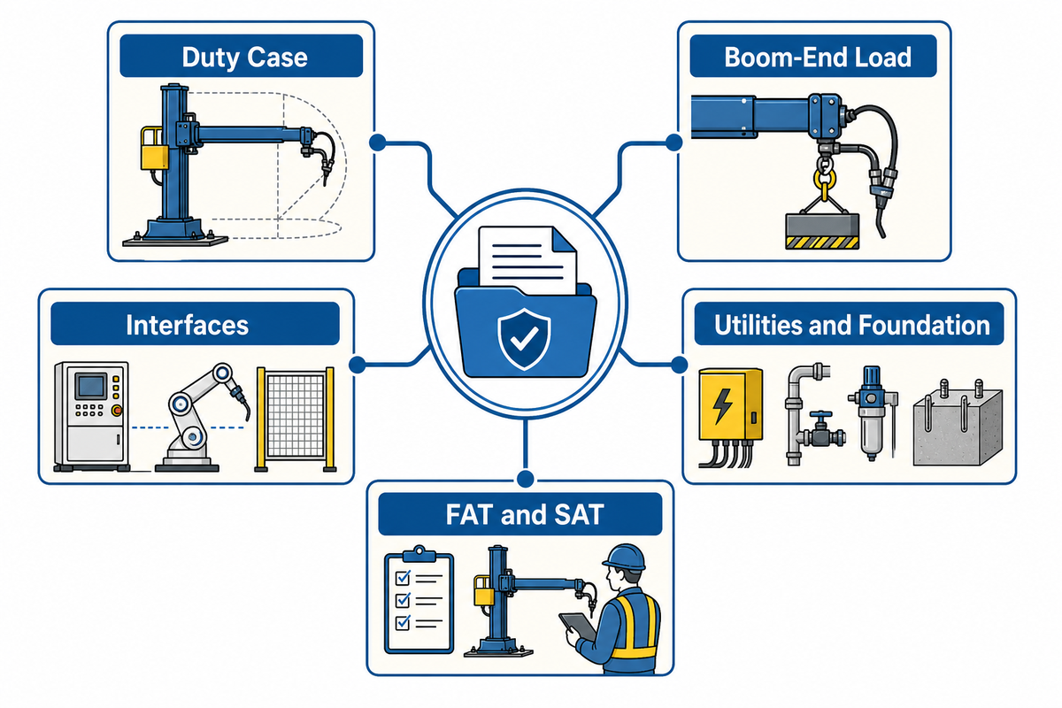
| Engineering field | Minimum controlled record | Why a catalogue is not enough |
|---|---|---|
| Duty case | Workpiece, joint path, process, duty pattern | One machine can serve different jobs |
| Boom-end load | Mass, offset, reach, direction, duration | A maximum value does not identify the tested stack |
| Interfaces | Signal, protocol, owner, fail response, test | “Included” does not assign integration responsibility |
| Utilities and foundation | Approved supplier sheet and site-readiness record | Installed conditions are site-specific |
| FAT and SAT | Method, values, witness, deviation, disposition | A demonstration is not automatically an acceptance test |
1. Start With the Acceptance Case, Not the Model Name
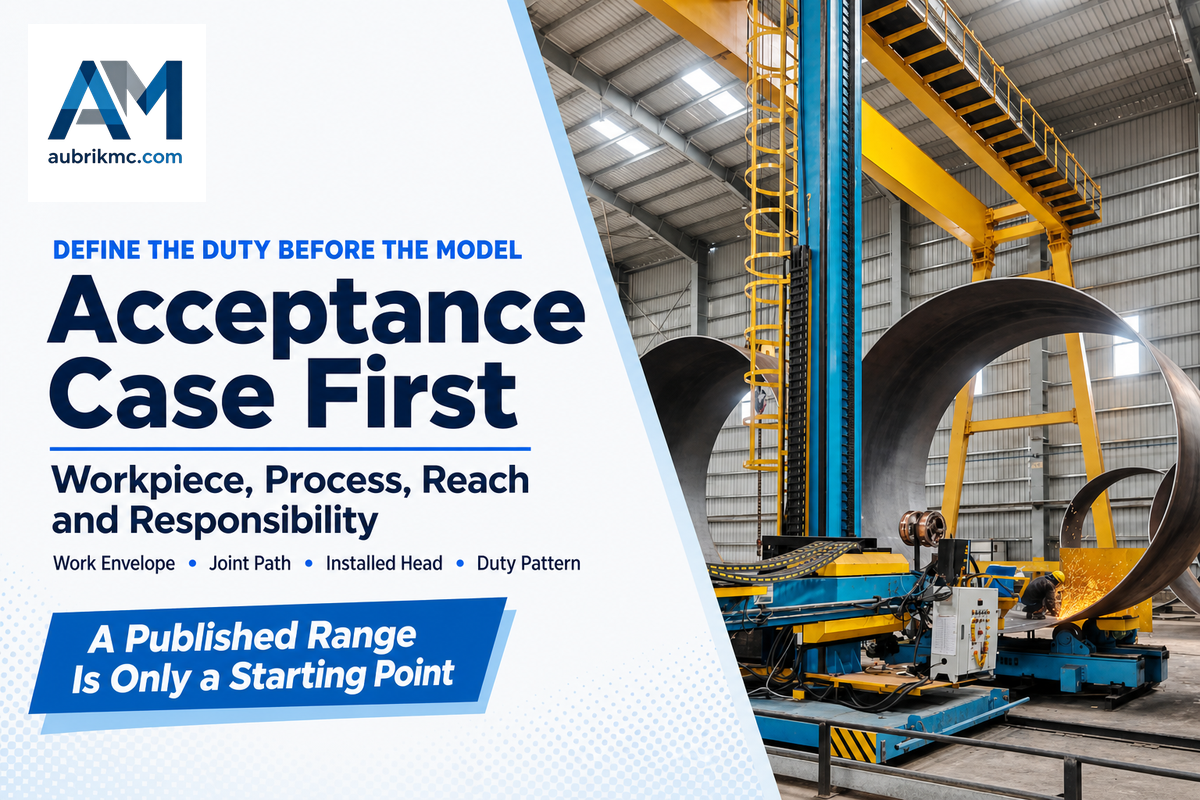
Before comparing models, write one duty-case paragraph that fixes the workpiece envelope, joint path, welding process, working reach, installed head package, companion motion, operating pattern, and responsibility split. That paragraph becomes the reference for the quote, drawing review, FAT, SAT, and handover.
Aubrik’s published column-and-boom specification table currently lists four model classes: AM-CB-30 at 3 × 3 m with a stated 150–500 kg range; AM-CB-40 at 4 × 4 m and 300–800 kg; AM-CB-50 at 5 × 5 m and 500–1,200 kg; and AM-CB-60 at 6 × 6 m and 800–2,000 kg. The listed motion-speed range is 120–3,000 mm/min. These are first-party catalogue values, not independent proof of an installed condition or a complete statement of every custom size the supplier might quote.
Each model row lists the same 120–3,000 mm/min motion range. Neither the 120 mm/min endpoint nor the 3,000 mm/min endpoint proves loaded speed stability at the buyer’s required reach; that needs a controlled test condition and agreed tolerance.
Published Range vs Acceptance Condition Matrix
| Catalogue field | Condition still missing | Required evidence | Limitation |
|---|---|---|---|
| 3 × 3 m model class | Required vertical and horizontal work envelope | Approved layout and duty case | Nominal class is not usable stroke proof |
| 4 × 4 m model class | Torch access and collision envelope | Reach study or drawing review | No universal clearance applies |
| 5 × 5 m model class | Base, rail, and installation arrangement | Approved general arrangement | Site structure is project-specific |
| 6 × 6 m model class | Access, lifting, and service path | Site-readiness inspection | Size can increase integration demands |
| 150–500 kg stated range | Installed mass and offset | Signed load-stack schedule | First-party published data |
| 300–800 kg stated range | Maximum working reach and direction | Configured FAT test sheet | No generic deflection value supplied |
| 500–1,200 kg stated range | Dynamic cable and hose effects | Observed motion record | Routing changes the installed condition |
| 800–2,000 kg stated range | Future allowance and approval owner | Contract load revision | Allowance is not free capacity |
| 120–3,000 mm/min | Required setpoints, path, and loaded condition | Time/distance or control trace | Published range is not speed-stability proof |
| Welding-process compatibility | Exact source, head, services, and sequence | Interface register and function test | Not a welding-procedure qualification |
| Automatic operation | Permissives, limits, alarms, recovery | Cause-and-effect witness record | Safety design remains risk-dependent |
This is the first rule of the 11-Point Quote-to-Arc Acceptance Chain: a published range starts the conversation; the acceptance case defines what must be proved. Even a heavy-duty label remains incomplete until the quoted condition and evidence are fixed.
2. Freeze the Real Load Stack at Maximum Working Reach
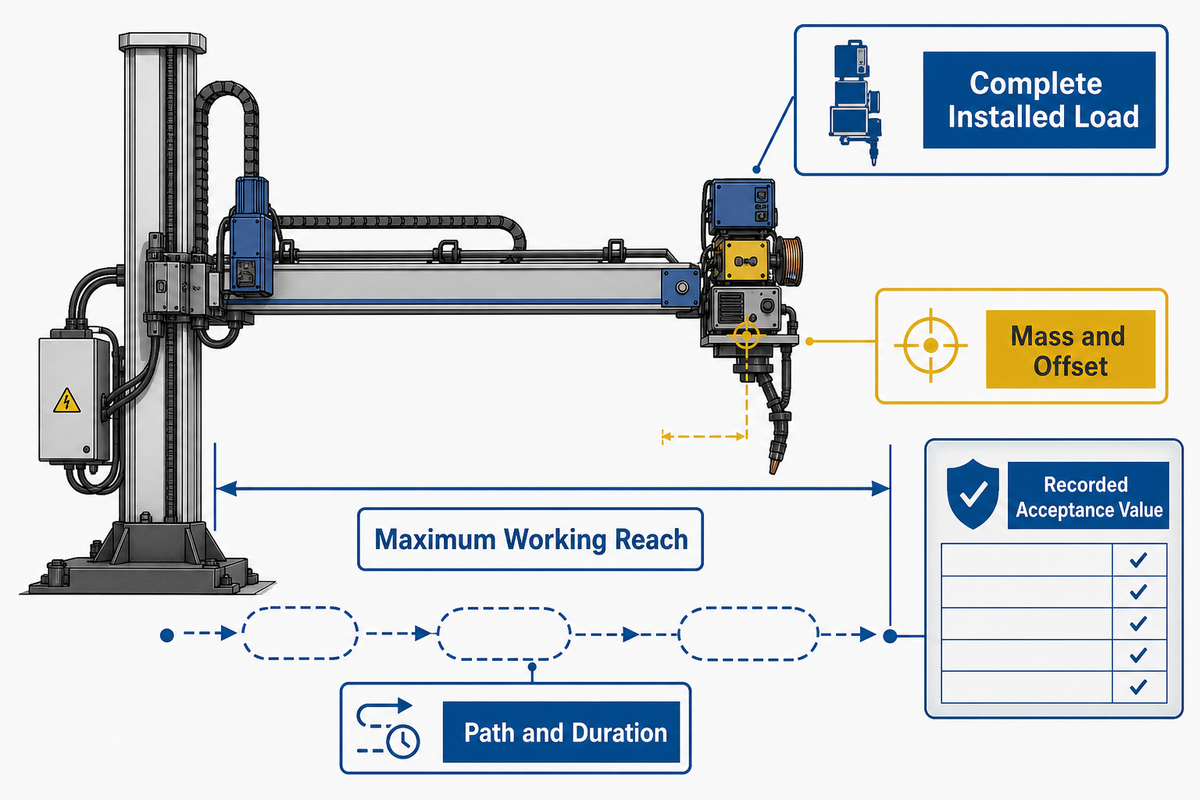
Boom-end capacity documentation should prove the complete installed load at the agreed working reach and motion condition. It should name every item, its mass and offset, the path and duration of the test, the measurement method, the acceptance value, and the people who approve changes.
Count more than the weld head. A complete schedule may include a slide, torch, wire feeder, flux equipment, seam tracker, camera, brackets, cable carriers, hoses, and an agreed future allowance. A component mounted away from the boom’s reference point can matter differently from the same mass close to it, so offset belongs beside mass.
What should boom-end capacity documentation prove before acceptance?
It should prove five things: the installed stack is complete; each item’s mass and offset are known; the boom is at the agreed maximum working reach; the motion direction and test duration match the duty case; and the measured result meets a contract value. Documentation should identify the drawing and load-schedule revisions, measurement instrument, setup photographs, raw values, witness, deviation status, and approval signatures. Cable and hose routing should match the intended configuration rather than being tied back for convenience. If any field changes after approval, the responsible parties should assess the change and decide whether a repeat test is needed.
Use a boom-end load calculator to organize the stack, not to replace the supplier’s engineering review. ISO 17662:2025 supports a disciplined approach to calibration, verification, and validation of welding-variable equipment; it does not provide a universal column-and-boom deflection or speed tolerance.
3. Write the Welding Automation Cell Interface Schedule Before Asking for Quotes
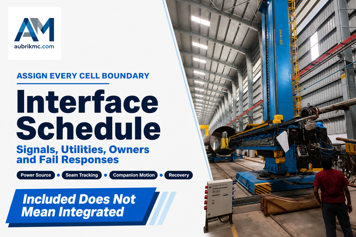
An interface schedule should assign every device, signal, utility, and failure response in the welding system to a named party before bids are compared. For each boundary, record direction, normal state, protocol or hardwired condition, permissive, alarm, loss-of-signal response, test owner, and required evidence.
This register normally touches the manipulator, power source, weld head, seam tracking, operator controls, extraction, flux recovery where applicable, and companion motion. If a positioner or turning roll is involved, link mechanical and control ownership rather than writing “synchronized” with no definition. Adjacent field experience makes the point: a physical connector isn’t enough when the robot or controller can’t interpret the signal.
Which control-system interfaces must a welding manipulator RFQ define?
Define start/ready signals, welding-source status, motion permissives, emergency and protective-stop interactions, travel limits, seam-tracker enable and fault states, companion-axis commands, extraction or flux-system status, alarms, reset authority, safe recovery, data retention, and the loss-of-communication response. Name whether each point is hardwired or networked, who supplies each side, and who witnesses its test.
For companion-equipment fundamentals, see the welding rotators and turning rolls guide. Different weld processes need different interfaces; this article doesn’t turn SAW, MIG/GMAW, TIG, cladding, or pipe welding into one generic process recipe.
4. Define Factory Readiness and Utility Boundaries
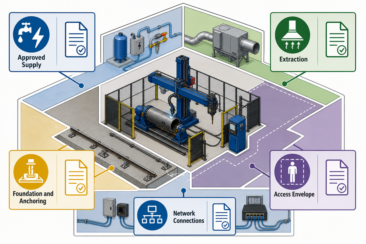
Factory readiness is a dated, owned record, not a sentence saying “site by buyer.” It should identify the approved supply characteristics, protective-conductor boundary, air or process-gas interfaces where used, extraction, floor or rail foundation, anchoring, access envelope, lifting route, network connections, and materials needed for dry runs.
Don’t copy utility values from another project. Ask the selected supplier to issue a controlled utility and installation sheet, then add the site owner, ready date, inspection method, and SAT evidence for every line. Approved layouts should show operating, guarding, service, and removal space as separate needs.
IEC 60204-1 provides relevant electrical-equipment-of-machines scope. In the United States, OSHA 1910.212 also makes guarding and anchoring real acceptance questions. Neither source supplies your site’s voltage, foundation design, extraction duty, or access geometry.
5. Turn Safety Functions Into Witnessed Tests
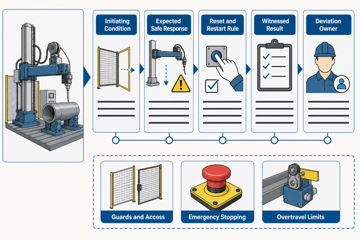
A witnessed safety test names the function, initiating condition, expected safe response, reset and restart rule, witness, result, and deviation owner. Its contents should come from the applicable risk assessment and integrated-cell design, not from a generic checklist copied into every project.
“One or more methods of machine guarding shall be provided to protect the operator.”
Typical test subjects include guards and access, emergency stopping, overtravel limits, loss of power or control signal, restart behavior, and hazardous-energy isolation information. “Typical” doesn’t mean mandatory or complete. Responsible designers must decide the functions and required risk reduction for the actual machine and use environment.
ISO 13849-1:2023 gives a methodology for safety-related control-system parts; it does not assign one universal required performance level to all welding manipulators. OSHA 1910.147 addresses hazardous-energy control during servicing and maintenance in its jurisdiction, but this guide is not a site lockout/tagout procedure.
6. Normalize Every Supplier Quote With One RFQ Table
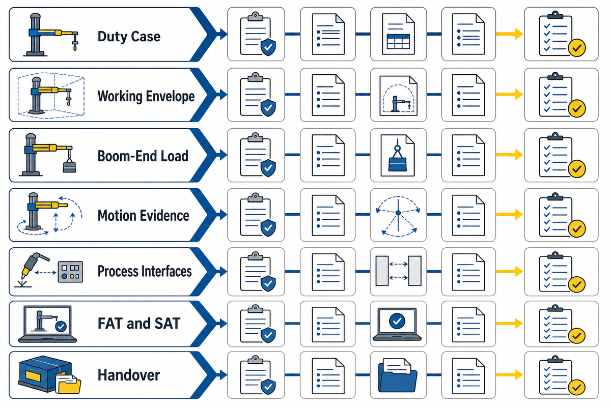
Compare quotations only after every bidder answers the same duty, load, interface, utility, safety, test, and handover fields. A catalogue maximum without the requested condition is “not comparable,” not a pass. This table also exposes exclusions early, when responsibilities can still be priced and assigned.
RFQ checklist — require every bidder to complete the same fields:
| Parameter | Recommended range | Why it matters | How to verify |
|---|---|---|---|
| Duty case | Buyer-defined workpiece, process, joint path, and duty pattern | Sets the actual production job | Approved duty statement |
| Working envelope | Project-defined reach, stroke, and access | Prevents model-class shorthand | Layout and reach review |
| Boom-end load | Signed stack, offset, reach, direction, duration | Makes capacity comparable | Load schedule and FAT record |
| Motion evidence | Agreed setpoints, path, instruments, tolerance | Separates range from performance | Recorded configured test |
| Process interfaces | Named services, signals, states, and owner | Closes multi-vendor gaps | Interface register and function test |
| Utilities and site work | Supplier-issued values plus buyer owner/date | Makes installation releasable | Readiness record and SAT |
| Safety deliverables | Project risk-assessment outputs and records | Avoids generic function assumptions | Witnessed cause-and-effect tests |
| FAT and SAT | Condition, method, value, witness, rejection rule | Defines what “pass” means | Signed protocols and deviations |
| Handover | Contract-defined records, training, spares, backups | Protects operation and maintenance | Indexed transmittal and punch list |
Once the duty case is frozen, a column-and-boom sizing selector can help shortlist a class. It shouldn’t erase the engineering review or convert an incomplete field into an assumption.
Have a completed duty case? Ask Aubrik to review the load, interface, and acceptance fields against a proposed configuration. Open the RFQ review form →
7. Build a Weld Manipulator FAT That Tests the Promised Condition
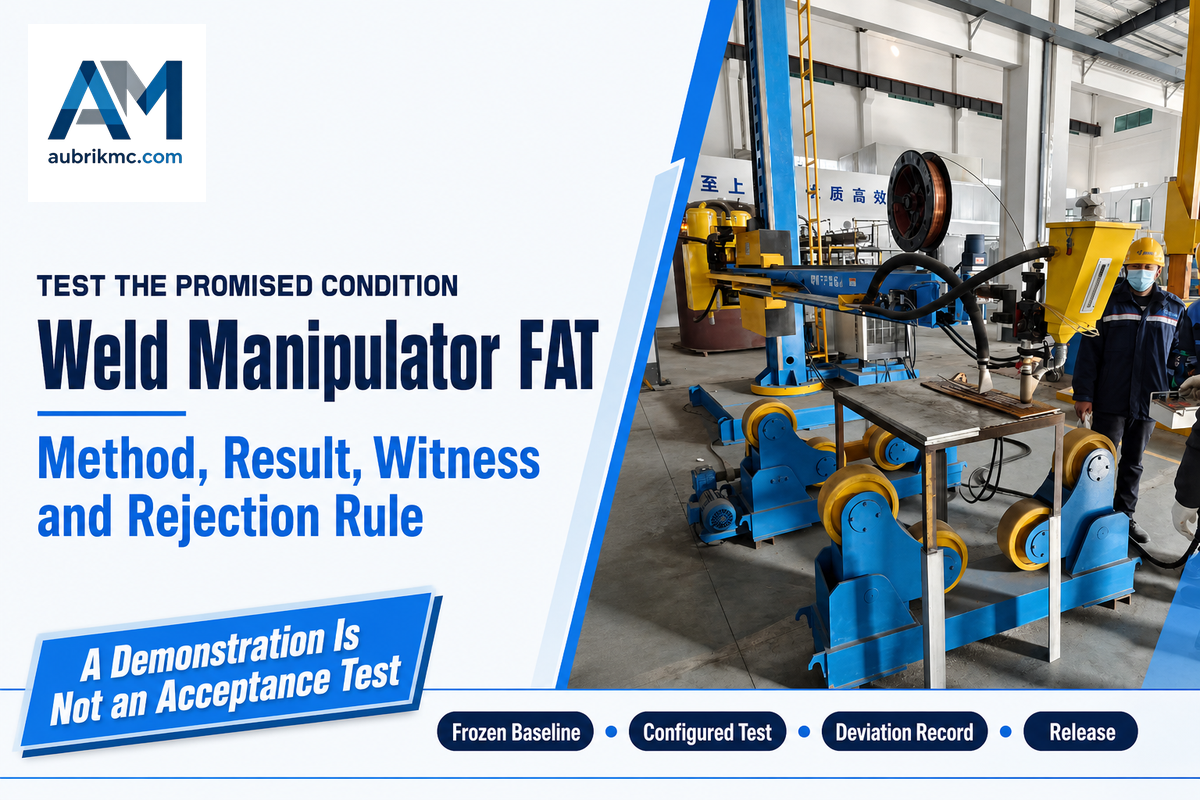
A useful FAT traces each promised condition to a test method, configured machine state, measured result, witness, record owner, and rejection rule. It confirms what’s ready before shipment; it shouldn’t hide unavailable equipment, substitute a no-load demonstration, or carry unresolved deviations into a silent pass.
- Freeze the baseline — approve the specification, drawings, load schedule, software revision, interfaces, test methods, tolerances, and witnesses.
- Prepare the evidence — identify instruments, verification status, forms, configured options, test pieces, and responsibility for each record.
- Witness configured tests — run the agreed load, reach, path, duration, controls, alarms, limits, and process-interface checks.
- Record deviations — state the observed result, affected requirement, owner, due date, retest need, and approval authority.
- Sign shipment release — release only the agreed condition, with open items explicitly classified and transferred.
How do you verify welding head stability during FAT?
First, install the approved head package and cable/hosing arrangement. Move to the specified reach and orientation, then run the agreed path and duration. Record the chosen indicators, such as measured position, visible vibration criterion, or weld-related observation, using the contract method. Compare the result with the project tolerance, log deviations, and repeat after any change that could affect the condition.
FAT and SAT Evidence Matrix
| Evidence item | FAT question | SAT question | Limitation/owner |
|---|---|---|---|
| Approved load stack | Was the configured stack tested? | Did installation change the stack or routing? | Buyer/supplier change approval |
| Reach and motion | Were agreed positions and paths run? | Does the installed layout restrict them? | Project tolerance controls |
| Control revision | Was the approved software tested? | Do site interfaces use the same revision? | Integrator owns configuration record |
| Safety functions | Do machine-level responses match design? | Do installed guards and cell interlocks respond? | Risk assessment sets the list |
| Power and bonding | Are machine records complete? | Is the final site connection verified? | Applicable engineering rules control |
| Companion motion | Was simulated or actual coordination tested? | Does the installed device exchange correct signals? | Named interface owner |
| Extraction/flux systems | Were permissives available? | Does the final system operate and alarm? | Process-specific and site-specific |
| Deviations | Were open items classified before shipment? | Were transferred items corrected and retested? | No silent carry-forward |
| Production condition | Was the agreed factory condition demonstrated? | Is production-representative operation released? | Weld acceptance remains a separate axis |
IEC 62381:2024 distinguishes factory, factory-integration, site, and site-integration testing in process-industry automation. Used by adaptation, its plan-test-document logic is helpful here; it is not a welding-manipulator certification or universal legal requirement.
8. Use SAT to Prove the Installed Column and Boom System, Not Repeat FAT
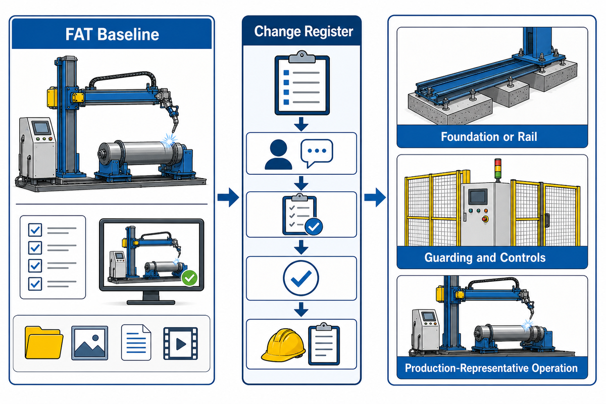
FAT proves the agreed factory configuration; SAT proves the installation-specific system. Retain valid factory evidence, then test what changed: foundation or rail, anchoring, supplies, protective bonding, guarding, controls, interfaces, extraction, companion equipment, and production-representative operation.
Start SAT with a change register. For every difference from the FAT baseline, state the effect, responsible reviewer, new test, and result. A changed cable route may alter movement; a different positioner may change signals; a site guard may alter access or reset behavior. Copying the FAT result forward without reviewing the changed condition leaves the acceptance trail incomplete.
SAT should also confirm that local operators and maintenance staff can identify normal controls, fault indications, authorized reset/recovery, and isolation points within their roles. It shouldn’t become an uncontrolled production trial. Use a released method, suitable materials, named witnesses, and a punch-list rule.
9. Close Handover With Records, Training, Spares, and Punch-List Rules
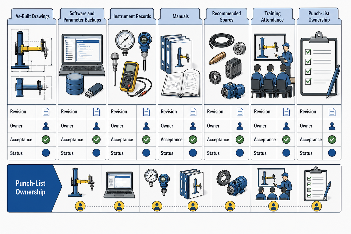
Handover closes when each contract deliverable has a revision, format, language, owner, acceptance check, and status. A folder full of files isn’t an index, and attendance at a demonstration isn’t proof that all role-specific training and maintenance information were delivered.
A handover index may include as-built drawings, electrical documents, software and parameter backups, instrument records, manuals, maintenance isolation points, recommended spares, training attendance, warranties, open items, owners, and due dates. Exact deliverables are contractual; this isn’t a universal statutory package.
For hazardous energy, the supplier should clearly identify energy sources, isolation provisions, and relevant maintenance information. At the site, the employer’s applicable program and responsible personnel still control the actual procedure. Close punch-list items by evidence and retest where required, not by deleting a line after the due date.
10. Know When Not to Accept, or When a Manipulator Is the Wrong Fix
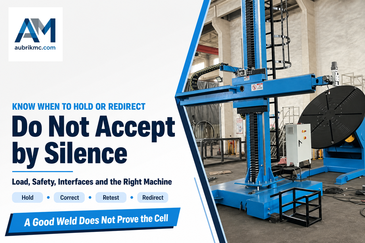
Hold acceptance when the agreed load condition was unavailable, values weren’t recorded, interface ownership is missing, a safety test failed, an uncontrolled change occurred, or required records remain open. Redirect the problem when it belongs to workpiece positioning, welding procedure, fit-up, extraction, or another part of the cell.
| Condition | Decision | Evidence needed | Boundary |
|---|---|---|---|
| Published maximum, no test condition | Hold as not comparable | Load, reach, method, tolerance | Supplier/project-specific |
| Code-accepted weld, machine gaps open | Hold machine/cell release | Mechanical, control, electrical, safety records | Two acceptance axes |
| Pipe-specific sizing or operation | Redirect | Pipe duty and companion-motion review | Owned by pipe guide/project documents |
| Failed safety response | Do not release | Correction, review, witnessed retest | Risk assessment and applicable law |
| Unresolved punch list | Hold or formally condition release | Owner, due date, impact, approval | Contract controls |
ASME BPVC Section IX addresses welding, brazing, and fusing procedure/personnel qualification. AWS D1.1/D1.1M addresses structural-steel welding within its scope. Neither a welder qualification nor an accepted weld proves manipulator load, control, electrical, guarding, integration, or site acceptance.
For pipe-specific sizing, seam tracking, operation, and maintenance, use the pipe welding manipulator guide and the controlled project documents.
Key takeaway
A code-accepted weld and an accepted manipulator answer different questions. Close both evidence trails before production release.
Need a configuration review? Send the completed duty case, load stack, and interface schedule so the proposed equipment and acceptance plan can be reviewed together. Start the technical RFQ →
Frequently Asked Questions
What information should a welding manipulator RFQ include?
State the workpiece and joint envelope, process, reach, complete boom-end load stack, motion duties, companion equipment, controls, utilities, safety deliverables, FAT, SAT, documentation, training, spares, and boundary owner. Ask every bidder to answer the same fields and list exclusions. Require a test condition, method, tolerance, record, and approval owner for each promised value. Also identify which changes force a drawing update or retest. A catalogue model becomes comparable only when the requested condition and evidence are the same.
What is the difference between FAT and SAT for a column-and-boom welding cell?
FAT checks the approved machine and configured functions before shipment using agreed methods, records, witnesses, and rejection rules. SAT checks the installed condition: supply, foundation or rail, anchoring, guarding, bonding, local controls, interfaces, extraction, companion equipment, and representative operation. SAT retains valid FAT evidence, then tests site-specific changes and risks.
How should boom-end capacity be documented?
Record every installed item, its mass and offset, maximum working reach, motion direction, duration, measurement method, and acceptance value. Include the weld head, slides, torch, feed equipment, tracker, camera, cable and hose supports, brackets, and any approved future allowance. Buyer and supplier should sign the same controlled schedule before FAT and assess later changes against that baseline.
Does an AWS- or ASME-qualified weld prove that the manipulator passed acceptance?
No. Welding-code acceptance addresses a weld, procedure, or person within the invoked code’s scope. Manipulator acceptance separately covers load, motion, controls, electrical work, safety functions, integration, records, and the installed condition.
When should a buyer refuse shipment or final acceptance?
Hold shipment when the approved FAT condition was unavailable, the installed load or reach differs from the quotation, required values weren’t recorded, or safety and interface deviations remain unresolved. Hold final acceptance when utilities, anchoring, bonding, guarding, interlocks, companion motion, extraction, training, records, backups, spares commitments, or punch-list ownership don’t match the contract. A controlled deviation can be assessed, corrected, and retested; an unresolved difference should never become a pass by silence.
Should pipe welding, SAW, TIG, MIG, or cladding use the same acceptance plan?
Use the same evidence structure, but change the process-specific interfaces and test conditions. Flux handling, tracking, torch services, companion rotation, extraction, and procedure requirements differ. Project contracts, risk assessments, and welding documents control the final plan.
Reviewed Scope and Related Resources
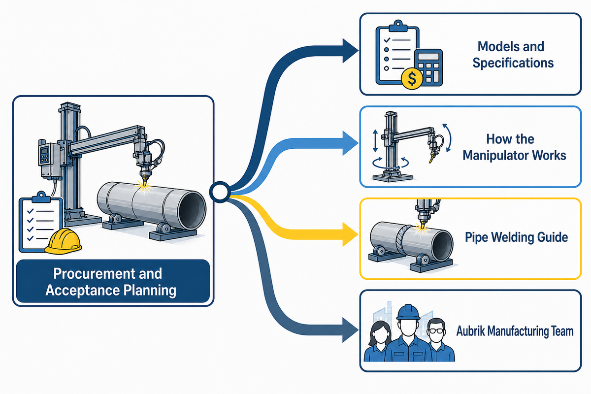
This guide is limited to procurement and acceptance planning. Learn about Aubrik’s manufacturing team. The framework isn’t a substitute for a machine designer, responsible engineer, risk assessment, applicable law, or the project’s controlled specifications.
- Column & Boom Welding Manipulators, models and specifications
- How a Column and Boom Welding Manipulator Works
- Welding Rotators and Turning Rolls Guide
- Pipe Welding Manipulator Guide
References & Sources
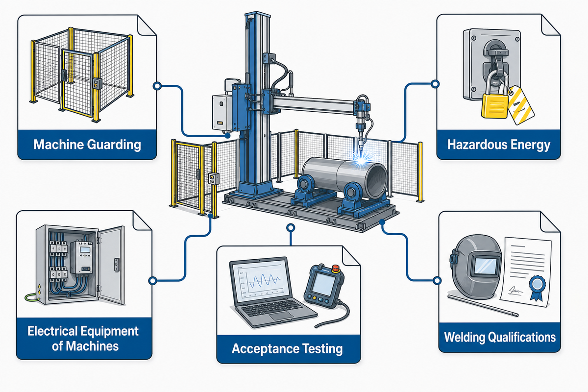
- OSHA 29 CFR 1910.212, General Requirements for All Machines
- OSHA 29 CFR 1910.147, Control of Hazardous Energy
- ISO 17662:2025, Welding Equipment Calibration, Verification and Validation
- ISO 13849-1:2023, Safety-Related Parts of Control Systems
- IEC 60204-1, Electrical Equipment of Machines
- IEC 62381:2024, Automation-System Acceptance Testing Framework
- ASME BPVC Section IX, Welding, Brazing and Fusing Qualifications
- AWS D1.1/D1.1M, Structural Welding Code, Steel