Entrez en contact avec Aubrik Company


Le rechargement TIG est un procédé qui dépose une couche de métal fondu sur un composant dont la surface doit présenter des propriétés différentes de celles du métal de base qui la supporte. Les informations nécessaires à une demande de matériel bien définie partent de la surface finale : son alliage, son épaisseur résiduelle, son environnement de service et ses critères d’acceptation. La vitesse de soudage annoncée vient ensuite.
Mis à jour en septembre 2026 · Guide de sélection des procédés et du matériel
Qu’est-ce que le rechargement TIG ?

Le rechargement TIG est un procédé de soudage par fusion qui utilise une électrode en tungstène non consommable pour déposer un métal d’apport sur une surface métallique. TIG signifie « tungsten inert gas » ; la désignation officielle du procédé est le soudage à l’arc sous gaz avec électrode de tungstène. Le gaz de protection protège le bain de fusion tandis que la couche déposée adhère au substrat.
La commande indépendante du métal d’apport et de l’arc distingue le procédé TIG d’un procédé à électrode consommable. Ici, le tungstène produit l’arc ; le fil d’apport fournit le métal ajouté. Sélectionnez le fil de soudage correspondant au dépôt prescrit. Le rechargement ou placage par soudage dépose du métal afin de protéger la surface. Le matériau de base supporte la charge au sein d’une combinaison de matériaux qualifiée.
La terminologie est importante. Dans sa présentation du rechargement ou placage par soudage, TWI traite de la protection des surfaces au moyen de matériaux déposés. Le rechargement soudé résistant à la corrosion répond aux conditions de service. Le rechargement dur vise la résistance à l’usure ; la reconstitution d’une cote usée et le beurrage d’un assemblage de métaux dissemblables répondent à des objectifs différents.
Piège lors de la consultation : il apparaît lorsqu’une demande portant uniquement sur le « rechargement ou placage par soudage » entraîne des offres correspondant à plusieurs travaux différents. Décrivez la zone exposée et la fonction qu’elle doit remplir avant d’aborder la machine. La portée d’étanchéité d’une vanne et un arbre érodé peuvent tous deux nécessiter un apport de métal, mais leurs critères d’acceptation ne sont pas nécessairement identiques.
Fil froid ou fil chaud : quel procédé de rechargement TIG convient ?

En TIG à fil froid, le métal d’apport est amené dans la zone de l’arc, tandis qu’en TIG à fil chaud, le fil est préchauffé à l’approche du bain de fusion. Le préchauffage peut réduire l’énergie que l’arc doit fournir pour faire fondre complètement le fil. La comparaison dépend de l’accès de la torche, de la maîtrise thermique et des caractéristiques requises pour le dépôt final.
Les systèmes conventionnels de chauffage résistif nécessitent une source de courant externe pour chauffer le fil. Le chauffage par induction constitue une autre solution. Demandez au fournisseur de présenter le circuit de chauffage et sa relation avec la pièce ; l’expression « fil chaud » ne couvre pas tous les éléments du système de rechargement ou placage par soudage.
TIG conventionnel à fil froid
- Le métal d’apport est introduit sans préchauffage distinct.
- L’arc fournit l’énergie nécessaire à la fusion du fil.
- Vérifiez le dépôt et l’accessibilité sur la pièce réelle.
TIG à fil chaud
- Le métal d’apport bénéficie d’un préchauffage distinct.
- Identifiez s’il s’agit d’un chauffage résistif ou par induction.
- Vérifiez le dépôt et l’accessibilité sur la pièce réelle.
Une étude de 2026 sur le rechargement par GTAW à fil chaud a comparé un fil chauffé par induction à un fil froid en acier inoxydable superausténitique déposé sur un acier à faible teneur en carbone. Son introduction traite de l’interaction avec l’arc dans d’autres systèmes de chauffage, mais cette comparaison n’était citée qu’à titre de référence. L’étude n’a pas démontré que tous les systèmes de chauffage résistif présentent cette instabilité.
À titre de clarification, l’exemple de consultation concernant le rechargement d’un alésage comprend une offre de rechargement à plat avec une ouverture pour la torche et une autre portant sur une tête de soudage permettant à la torche d’accéder à la surface intérieure. Une hausse du taux de dépôt annoncé ne résoudrait pas une collision entre la première torche et l’alésage. Demandez aux deux fournisseurs d’illustrer le passage du fil, le dégagement de la torche et une séquence de soudage complète sur le même plan.
Les têtes de soudage, les systèmes de commande du courant de soudage et ceux de l’alimentation du fil constituent l’ensemble du procédé. Le composant doit également être compatible avec un soudage TIG orbital ou avec le mouvement d’une tête rotative. Évaluez la configuration réelle des machines de soudage TIG du fournisseur avant de considérer leurs performances nominales comme équivalentes.
Pourquoi une faible dilution est-elle importante en rechargement soudé ?

La dilution mélange le métal de base fondu au métal d’apport fondu et modifie la composition chimique du métal déposé. Une dilution plus faible peut permettre de conserver la composition d’alliage requise, mais elle ne constitue que l’un des nombreux critères d’acceptation. La bonne fusion, l’épaisseur restante du rechargement et l’état final de la surface usinée doivent également répondre à toutes les exigences de l’application prévue. Lors du choix d’un substrat parmi une gamme telle que les tubes et tôles en acier de Baling Steel, consignez la nuance exacte, l’état de fourniture et la traçabilité des coulées avant l’essai de rechargement soudé.
L’étude menée par TWI en 2010 sur un rechargement en alliage 625 a constaté qu’un apport thermique identique ne produisait pas toujours une dilution identique. L’exemple en court-circuit présentant la plus faible dilution avait également une géométrie de cordon susceptible d’accroître le risque de manque de fusion au niveau des chevauchements. Ces résultats ne définissent pas une limite universelle de dilution et ne démontrent pas que toutes les soudures TIG à faible dilution sont défectueuses.
La chaîne de preuves de la surface finie est notre grille éditoriale permettant de relier le plan au composant contrôlé. Chaque ligne indique une transmission de preuve, et les valeurs d’acceptation doivent provenir de la spécification applicable et du mode opératoire de soudage qualifié.
| Étape | Preuves à demander | Lacune mise en évidence |
|---|---|---|
| Conditions de service | Milieu exposé et conditions de fonctionnement | Fonction de protection inadaptée |
| Matériau de base | Nuance, état et traçabilité | Hypothèse non étayée concernant le substrat |
| Matériau d’apport | Classification spécifiée et identification du lot | Nom commercial se substituant au contrôle du matériau |
| Mode opératoire de soudage | Qualification applicable et domaine de validité | Essai hors du périmètre prévu |
| Couche déposée | Preuves relatives à l’épaisseur et à la fusion | Aspect tenant lieu de preuve d’intégrité |
| Traitement thermique | Cycle et séquence requis, le cas échéant | Essai réalisé sur un état antérieur du matériau |
| Usinage final | Surépaisseur d’usinage et épaisseur résiduelle | Élimination de la couche protectrice prévue |
| Échantillonnage pour analyse chimique | Méthode, emplacements et état de surface | Analyse globale masquant les variations locales |
| Libération | Résultats prescrits de contrôle et d’acceptation | Échantillon attrayant sans preuve de libération |
Pour une pièce donnée à titre d’exemple et nécessitant une couche finie de 3 mm, un essai mesuré à 4 mm avant usinage laisse une question sans réponse. Après l’enlèvement prévu de 1 mm, la surface respecte-t-elle encore la composition chimique spécifiée ? Ces dimensions illustrent l’absence de preuve et ne doivent pas servir d’épaisseur de rechargement ou de surépaisseur d’usinage recommandée.
Adapter l’alliage de rechargement à la corrosion et à l’usure

Le choix du métal d’apport de rechargement part du mécanisme d’endommagement et de l’état du métal de base. La résistance à la corrosion, à l’abrasion et à l’usure à haute température impose des exigences différentes à l’alliage. Les matériaux à base de nickel, à base de cobalt ou contenant des carbures doivent être envisagés sur la base de conditions de service et de soudage étayées, et non retenus parce que leur nom commercial est connu.
L’Inconel 625 est un exemple courant d’alliage de nickel destiné aux milieux corrosifs. Pour d’autres combinaisons d’usure et de corrosion, des alliages de type Stellite et un rechargement dur au cobalt peuvent être envisagés. La présentation générale des matériaux de TWI fournit quelques exemples de cas, mais ne permet pas de remplacer un métal d’apport par un autre. Pour une utilisation dans les champs pétroliers et gaziers ou pour toute autre application, vous devez préciser le milieu, la température et le mécanisme d’usure prévu, après quoi vous pouvez demander à l’ingénieur en soudage compétent d’étudier les aspects métallurgiques. Une demande de produit portant sur les matériaux en alliage de nickel de TiAlloy peut permettre de déterminer les formes de matériau disponibles, mais la classification du métal d’apport et le mode opératoire de soudage qualifié doivent faire l’objet d’une confirmation distincte.
Classer séparément les procédés de rechargement dur
D’autres méthodes de soudage permettent d’autres procédés de rechargement. Le soudage à l’arc plasma transféré, souvent appelé soudage PTA, est une technique de rechargement. Le soudage à l’arc sous protection gazeuse avec fil-électrode fusible, notamment le soudage sous gaz inerte avec fil-électrode fusible ou soudage MIG, utilise un fil-électrode consommable. Le soudage à l’arc sous flux utilise un flux ; le soudage à l’arc avec électrode enrobée, ou SMAW, utilise des électrodes enrobées. Les alliages complexes à base de carbures et les rechargements en bronze nécessitent leur propre évaluation des matériaux et du procédé.
Objection de l’acheteur : la simple mention d’une désignation d’alliage connue ne signifie pas qu’un rechargement soudé résistera à ces conditions de service. Veuillez fournir votre justification et préciser le métal d’apport proposé, ainsi que les essais requis de corrosion, de dureté et tout autre essai lié aux conditions de service. La compatibilité et l’aptitude au service sont deux questions distinctes.
Spécifier la machine de rechargement en fonction de la pièce

La géométrie de la pièce détermine la trajectoire de la torche de soudage, les surfaces accessibles et la manière dont la pièce peut être supportée. Un alésage, une portée d’étanchéité et une virole longue peuvent nécessiter des mouvements différents. Considérez donc le plateau ci-dessous comme une grille de consultation et transmettez-le avec le plan réel après avoir vérifié chaque configuration proposée.
Le rechargement de tubes soulève également une difficulté : l’outillage proposé pourra-t-il maintenir l’orientation requise en position verticale comme horizontale ? Confirmez que l’accès à toutes les surfaces à recharger est dégagé avant de valider la configuration des mouvements.
| Caractéristique de la pièce | Question relative au mouvement | Preuve par plan ou essai |
|---|---|---|
| Alésage droit | Faire tourner la tête ou la pièce ? | Dégagement de la torche sur toute la course |
| Alésage profond | Comment la tête allongée est-elle supportée ? | Évaluation de la portée et de la déflexion |
| Passage sécant | La trajectoire peut-elle traverser l’ouverture ? | Marche à blanc et essai de transition |
| Portée d’étanchéité | La rotation peut-elle maintenir l’orientation de la torche ? | Accès à la face et disposition du bridage |
| Coude ou raccord | La pièce nécessite-t-elle une inclinaison contrôlée ? | Trajectoire et support dans chaque orientation |
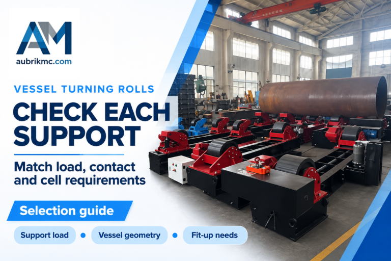
| Virole cylindrique longue | Des vireurs de soudage peuvent-ils la supporter pendant son déplacement ? | Évaluation de l’espacement des supports et de la dérive |
| Centre de gravité excentré | Quelles charges s’exercent pendant la rotation ? | Calcul de la masse, de l’excentration et de l’outillage |
| Pièce moulée lourde | Comment sera-t-elle chargée et réorientée ? | Trajet de levage et plan de manutention |
| Plusieurs familles de pièces | Quels éléments changent d’un lot à l’autre ? | Démonstration du changement de série et outillages |
Un article publié dans une revue professionnelle sur le projet de vannes de Polysoude et Arc Energy Resources permet de confronter ces questions à la réalité. Dans ce récit émanant des fournisseurs, ils décrivent des pièces moulées de 27 tonnes qui dépassaient la capacité de levage d’un pont roulant existant de 15 tonnes. La manutention des pièces moulées a contribué à déterminer l’agencement de l’installation. Il s’agissait de leur projet, et non d’un cas de production Aubrik ni d’une étude comparative indépendante.
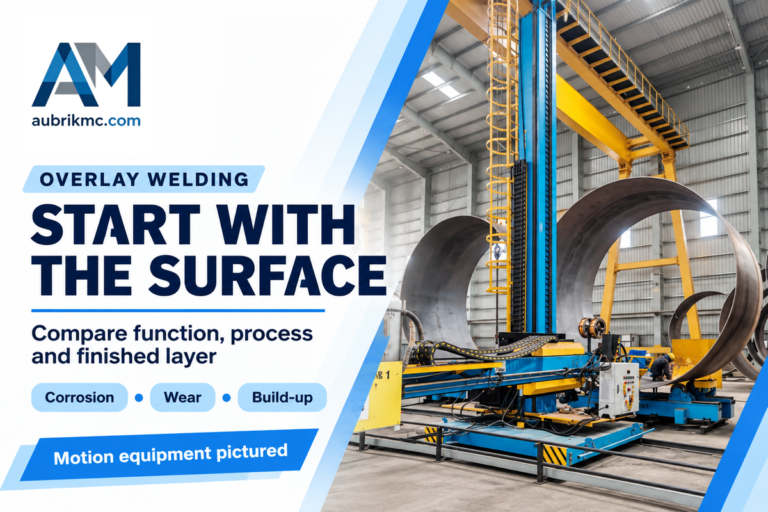
Pour différents aspects du problème de mouvement, les équipements Aubrik de rotation et d’inclinaison des pièces et les plateformes de torche à colonne et flèche répondent à divers besoins. Les vireurs de soudage pour pièces cylindriques constituent des options supplémentaires. La sélection du matériel peut intervenir après confirmation de l’ensemble du procédé de soudage, des estimations de charge et de la portée de la torche.
Quelles preuves doivent qualifier le procédé de rechargement soudé ?

Le code de construction, la spécification de l’acheteur et le critère de service détermineront la voie de qualification. Les preuves de qualification du mode opératoire de soudage, de qualification du personnel et d’acceptation de la production correspondent à des niveaux de preuve différents. Un certificat de machine de soudage ou l’aspect d’un échantillon ne permet pas de satisfaire ces trois éléments. Convenez des enregistrements requis et des conditions d’essai avant que le fournisseur ne réalise un dépôt d’essai.
La norme ISO 15614-7:2016 traite spécifiquement de la qualification des modes opératoires de rechargement par soudage ; son catalogue public fait état d’une confirmation en 2022. Le domaine d’application public distingue la réparation par reconstitution et le beurrage de métaux dissemblables. Lorsqu’une voie conforme au code de construction ASME s’applique, vérifiez l’édition de la section IX du BPVC, répertoriée publiquement dans une édition de 2025, exigée par le contrat.
Le formulaire public QW-484A de l’ASME est un document de qualification des performances du soudeur. Ses champs relatifs aux essais de pliage et aux macrographies du rechargement ne doivent pas être confondus avec un dossier complet de qualification du mode opératoire de soudage ni avec l’ensemble des exigences d’acceptation de la production. Veillez à ce que la partie responsable identifie les qualifications applicables du mode opératoire, du soudeur et de l’opérateur de soudage pour la technique de soudage réelle.
L’intégrité du substrat est également importante. Dans leur étude de 2019 sur le GTAW à fil chaud, Silwal, Walker et West ont testé un métal d’apport Inconel 625 chauffé par résistance sur de l’acier inoxydable 347, à des courants principaux de 60 à 100 A, et ont observé une fissuration de la zone affectée thermiquement dans la plage de courants supérieurs. Une couche formée ne peut donc pas être considérée indépendamment du matériau sur lequel elle repose. La combinaison et les conditions auxquelles elle sera soumise doivent être examinées au moyen d’essais.
La sécurité dépend à la fois des matériaux et du lieu de travail. Les recommandations du NIOSH sur la ventilation pendant le soudage présentent les risques liés aux fumées propres à chaque alliage et incluent les matériaux contenant du nickel et du chrome. La fiche d’information de l’OSHA sur les fumées de soudage indique que les gaz de protection peuvent déplacer l’oxygène. La faible visibilité des fumées ne réduit pas la nécessité d’évaluer l’exposition, la ventilation ou la maîtrise appropriée des espaces confinés.
La position doit également figurer dans les enregistrements d’essai. Le guide Aubrik des positions de soudage des tôles et des tubes en présente la terminologie ; ce sont les règles de qualification applicables qui déterminent les positions couvertes.
Comparer le coût par composant rechargé accepté

Le coût par composant rechargé accepté correspond au coût total du lot divisé par le nombre de pièces conformes aux critères de libération prédéfinis. Il convient d’inclure le coût de la préparation du procédé, du dépôt, de la finition et du contrôle, ainsi que celui des travaux non conformes. Le périmètre comptable doit rester identique pour les deux coûts. Les hypothèses relatives à la capacité et à la durée de vie doivent être analysées séparément de ce coût de lot.
« Mais il ne s’agit vraiment pas simplement de savoir quel procédé de soudage est plus rapide qu’un autre. »
Ce point est soulevé dans la discussion sur l’assemblage et le changement de série. Il ne s’agit pas d’une référence comparative reposant sur un coût de rechargement mesuré. Leur lien avec le fournisseur doit être pris en compte. D’autres travaux distincts sur les coûts de la fabrication additive à l’arc et au fil expliquent pourquoi la taille du lot et le post-traitement doivent être inclus dans le périmètre de calcul des coûts indiqué. Leurs prix ne correspondent pas à ceux du rechargement TIG.
| Poste inclus dans le lot | Option A | Option B |
|---|---|---|
| Préparation et changement d’outillage | $300 | $400 |
| Travail à l’arc : main-d’œuvre et temps machine | $900 | $600 |
| Métal d’apport, pertes de matériau comprises | $600 | $500 |
| Gaz et autres consommables | $100 | $120 |
| Usinage et finition | $600 | $900 |
| Contrôle | $200 | $250 |
| Reprise supplémentaire | $100 | $400 |
| Frais généraux affectés au lot | $200 | $250 |
| Coût total inclus | $3,000 | $3,420 |
| Pièces mises en production | 20 pièces | 20 pièces |
| Pièces acceptées à la clôture de l’essai | 20 pièces | 18 pièces |
| Coût par composant accepté | $150/pièce | $190/pièce |
Les données ont été inventées pour cet exemple ; il ne s’agit ni d’une offre Aubrik ni de résultats d’usine. Les deux options sont soumises à la même exigence finale. À la fin de l’étude de cas, les deux éléments non acceptés de l’option B restent rejetés et leur coût de traitement demeure inclus dans le total de l’option B. Les coûts de transport, les taxes, l’achat du matériel et le coût lié à la durée de vie des pièces sont exclus du total des deux options.
Le calcul est de $3 000 ÷ 20 = $150 par pièce acceptée, contre $3 420 ÷ 18 = $190. Bien que l’option B dépense $300 de moins pour le travail à l’arc, ses coûts supplémentaires en aval et son nombre inférieur de pièces acceptées inversent l’avantage apparent. Le service achats doit fixer le même périmètre comptable ; le service qualité doit définir l’acceptation ; la production doit consigner le temps écoulé et le changement de série.
Goulot d’étranglement caché : un dépôt plus rapide peut alimenter une file d’attente à l’usinage ou au contrôle sans accélérer la libération des pièces. Une étude sur la réparation hybride de composants par fabrication additive distingue en outre le coût de la réparation locale de celui des considérations plus larges liées à la chaîne d’approvisionnement. Utilisez cette grille de lot comme l’un des éléments de comparaison, en complément de l’acheminement, de la capacité et des coûts de possession.
Transformer les promesses d’automatisation du soudage TIG en une consultation vérifiable par essai

Une demande vérifiable concernant le soudage TIG comprend un plan réel du composant, un ensemble de procédé défini et un plan d’acceptation. Distinguez le maintien et le mouvement de la pièce de la source de courant de soudage, du chauffage du métal d’apport, de la protection gazeuse et du contrôle. Précisez qui fournit et qualifie chaque élément, et demandez les documents justificatifs des opérations nécessaires de rechargement soudé.
L’étude de 2026 sur le rechargement avec chauffage par induction soulève de nombreuses questions utiles sur le procédé de chauffage, la géométrie du cordon et les essais de matériaux. Elle ne crée pas de référence pour la productivité de l’ensemble du marché. Le rechargement soudé TIG automatisé doit pouvoir être justifié par les résultats d’un essai, et non uniquement par l’âge d’un système de commande ou par une vitesse de soudage annoncée.
- Identifiez le matériau de base, la spécification du métal d’apport et la surface à recharger.
- Fournissez les dimensions, la masse et le centre de gravité du composant, ainsi que l’accès à l’outillage.
- Définissez la couche finie, la séquence d’usinage et les conditions de service.
- Indiquez la spécification applicable, la voie de qualification et les preuves de libération.
- Précisez la composition des lots, les changements de série et le volume accepté requis.
- Attribuez la responsabilité de l’intégration du procédé, de la formation et des mesures de maîtrise sur site.
À retenir
Une comparaison du matériel de rechargement TIG doit porter sur le même composant fini, les mêmes critères d’acceptation et le même périmètre comptable. Le fournisseur de l’équipement de mouvement, celui de l’intégration du procédé et celui de la qualification doivent chacun être identifiés et fournir des preuves.
Aubrik a publié un périmètre permettant d’aborder les systèmes de positionnement et de manipulation de torche. Un procédé complet et qualifié de rechargement TIG doit être confirmé dans l’ensemble de fourniture convenu. Envoyez à Aubrik le plan de votre composant et vos exigences de rechargement pour engager cette discussion de périmètre, en prenant comme référence la gamme de manipulateurs de soudage pour la plateforme de torche.
Questions fréquentes
Les questions sur le procédé de rechargement TIG confondent souvent la vitesse du procédé, la protection de la surface et la sélection du matériel. Les réponses ci-dessous distinguent les différents enjeux. Le vocabulaire du procédé peut susciter une demande, mais les matériaux requis, la géométrie et les caractéristiques acceptables de la pièce terminée définiront la comparaison du matériel de soudage et le choix du prestataire du procédé.
Qu’est-ce que le rechargement par soudage ?
Le rechargement par soudage dépose une couche métallique afin de modifier la surface exposée d’un composant ou de rétablir une cote, le service prévu, les propriétés recherchées et l’épaisseur finale étant définis avant la comparaison des fournisseurs.
Le rechargement par soudage dépose du métal sur un composant afin de modifier les propriétés de sa surface exposée ou de rétablir une cote. Pour un rechargement TIG protecteur, un arc fait fondre le métal d’apport fourni séparément et une proportion maîtrisée du substrat, créant ainsi une liaison métallurgique. L’acheteur doit préciser la fonction prévue, l’épaisseur finale et les propriétés requises ; le seul nom du procédé ne définit pas l’acceptation.
Quel procédé est le plus rapide, le TIG ou le MIG ?
Le MIG dépose souvent le métal plus rapidement que le TIG à fil froid, mais le nombre de pièces acceptées nécessite une comparaison propre à l’application, avec le même alliage, la même géométrie de pièce, la même surface finie et les mêmes critères d’acceptation convenus.
Le soudage à l’arc sous protection gazeuse avec fil-électrode fusible dépose souvent le métal d’apport plus rapidement que le TIG conventionnel à fil froid, mais toute comparaison de rechargement doit porter sur le même alliage, la même géométrie et les mêmes exigences finales. Le fil chaud modifie la capacité de dépôt du TIG. Un rendement d’arc supérieur peut néanmoins perdre son avantage en raison des restrictions d’accès, de la préparation, de la finition ou des reprises. Demandez la durée totale de l’essai et le nombre de pièces acceptées plutôt que de choisir sur la seule comparaison des noms de procédés.
Quel est un inconvénient du soudage TIG ?
Le TIG à fil froid peut limiter la cadence de dépôt, tandis que les équipements automatisés à fil chaud imposent des exigences d’intégration supplémentaires concernant la puissance, l’alimentation en fil, l’accès de la torche et la coordination des mouvements sur le composant prévu.
Le TIG à fil froid peut limiter la cadence de dépôt, tandis que les équipements automatisés à fil chaud imposent des exigences en matière de puissance, d’alimentation en fil et de commande des mouvements. L’accès à l’intérieur d’un alésage peut limiter les possibilités de la torche. La maîtrise du procédé n’élimine pas non plus les risques de dilution, de fissuration du substrat ou de défaut de protection gazeuse. Comparez un composant représentatif aux spécifications d’acceptation avant de conclure que la maîtrise offerte par le TIG justifie le coût des équipements et de la production.
Quelle est la différence entre le rechargement ou placage par soudage et le rechargement soudé ?
Le rechargement ou placage par soudage est une notion plus large que le rechargement soudé, lequel implique spécifiquement un dépôt par fusion ; une demande adressée au fournisseur précise également la fonction recherchée : protection contre la corrosion, résistance à l’usure ou réparation dimensionnelle.
Le rechargement ou placage par soudage désigne l’ajout d’un matériau en surface et peut faire appel à plusieurs méthodes d’assemblage. Le rechargement soudé désigne un dépôt par fusion. Précisez explicitement s’il s’agit de protéger contre la corrosion, de résister à l’usure ou d’effectuer une réparation, car les terminologies employées par les fournisseurs se recoupent.
Une seule valeur de taux de dépôt permet-elle de comparer tous les systèmes TIG ?
Une valeur de taux de dépôt ne permet pas de comparer des systèmes sans appliquer les mêmes conditions d’utilisation et d’acceptation, notamment l’alliage, la géométrie, les exigences relatives à la surface finie et la production acceptée dans le périmètre convenu pour l’essai.
Non. Comparez le même alliage, la même géométrie, les mêmes exigences de finition et la même production acceptée. Une démonstration sur tôle plane ne constitue pas automatiquement un résultat de production pour le rechargement d’un alésage.
Références et sources
- Rechargement soudé en CRA : procédé, dilution et résistance à la corrosion TWI, 2010 ; résultats expérimentaux circonscrits.
- Matériaux et méthodes de rechargement ou placage par soudage TWI.
- Domaine d’application public de l’ISO 15614-7:2016 ISO ; catalogue vérifié en septembre 2026.
- Référencement de la section IX du BPVC, édition 2025 ASME.
- Formulaire QW-484A de qualification des performances du soudeur ASME, format suggéré en juillet 2023.
- Rechargement ou placage par soudage à fil chaud GTAW d’acier inoxydable superausténitique da Cruz et coauteurs, Applied Sciences, 2026.
- Rechargement ou placage par soudage à fil chaud GTAW : inconel 625 sur acier inoxydable 347 Silwal, Walker et West, 2019 ; résumé public d’une université.
- Étude de cas de rechargement soudé TIG d’un composant de grande taille Metal Working World Magazine ; témoignage émanant des fournisseurs Polysoude/Arc Energy Resources.
- Le fil chaud GTAW pourrait-il se généraliser ? Allford et Hebble, The Fabricator ; auteurs affiliés à ARC Specialties.
- Fabrication additive par arc-fil : coûts et propriétés mécaniques Kokare et coauteurs ; méthodologie d’évaluation des coûts d’un procédé connexe.
- Faisabilité économique de la réparation hybride de composants par fabrication additive Ghungrad et coauteurs ; modèle de réparation et de chaîne d’approvisionnement.
- Opérations de soudage : aspiration localisée NIOSH ; recommandations qualitatives sur les risques propres aux matériaux.
- Maîtrise des fumées et gaz dangereux pendant le soudage OSHA, fiche d’information de 2013.