Get in Touch with Aubrik Company

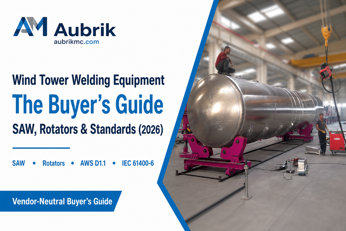
Quick Specs: Wind Tower Welding Equipment Stack
| Primary weld process | Submerged arc welding (SAW), single or tandem-wire |
| Rotating/positioning equipment | Welding rotators, turning rolls, self-aligning rotators |
| Torch positioning | Column-and-boom welding manipulators |
| Common rotator capacity range | 15-250 tons (market-observed, varies by vendor) |
| Governing standards | AWS D1.1 (US execution) / IEC 61400-6 (structural design). |
wind tower welding equipment is the group of machines – welding power sources, rotators, and manipulators – used to weld together steel plate into the cylindrical tower sections that support a wind turbine generating wind power for a wind farm. Updated July 2026. This equipment is built for wind tower construction specifically, not adapted from a generic fabrication line, and most buyers in this space are looking for answers to two key questions: what does a full production line for wind tower fabrication entail, and how is that line appropriately sized for a given tower section? This article will address both by examining vendor data, patent applications, and standards documents, rather than merely a manufacturer’s sales literature.
wind tower welding equipment can be broken down into five primary machine classes: submerged arc welding (SAW) power sources, welding rotators (also called turning rolls), column-and-boom manipulators, seam-tracking positioners, and NDT (non-destructive testing) stations. For the purpose of this guide, the size classification for the welding rotator component in wind-tower scale construction typically runs from 15 tons to 250 tons in standard equipment catalogs, with the specific weld-quality standard dictated by where the tower will be manufactured and ultimately marketed.
Key Takeaways
- Submerged arc welding (SAW) dominates mainly because of its superior deposition rate, not because it’s the only method that actually works in practice.
- There are actually three separate positioning machines necessary to create a tower section: one for rotation, another for supporting the welding torch, and, quite often, a third machine to track the seam.
- A 15-to-250-ton rotator/positioner capacity range reflects the current offering across multiple equipment vendors, not an established industry-wide standard.
- Currently, there is no single, universal global standard governing the welding of wind towers, as applicable regulations include AWS D1.1, IEC 61400-6, and EU CE-marking requirements which vary according to the geographical region and the scope of application.
- Reducing a tower’s shell wall thickness by roughly 20% can result in an increase of 50-70% in its fatigue life. This trade-off is a critical factor to consider before using wall thickness as a simple cost reduction strategy.
What Equipment Actually Welds a Wind Turbine Tower? (Fabrication Basics)
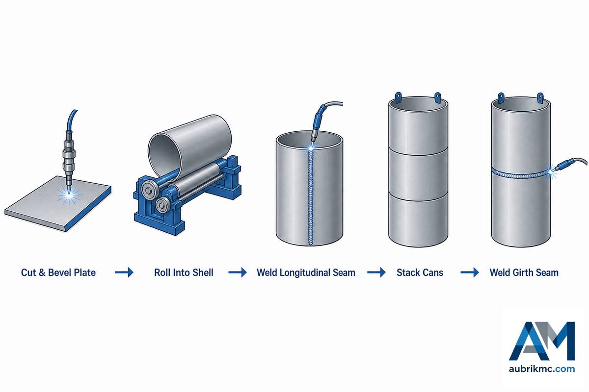
A wind turbine tower is fabricated from rolled steel plate sections that form individual cylindrical cans. These cans are then stacked and welded to create larger, assembled sections that ultimately comprise the entire tower. That traditional process, called “can welding,” involves stacking and welding smaller tubular segments together in sequence.
That can-welding sequence is accurately described in a 2023 research paper from Northeastern University’s College of Engineering, which documented turbine-tower work that gained recognition from Time Magazine. Nearly every wind tower welding equipment stack starts with this foundational methodology.
A Chinese patent (CN106695252A) for wind-tower-fabrication construction outlines a five-stage procedure that aligns with the practices observed in real-world manufacturing facilities. This sequence begins with cutting the raw material plate, preparing the groove for the weld, rolling the plate into a cylindrical shell, welding the longitudinal seam to close the shell, and finally proceeding to the assembly of sections using circumferential (girth) welds to join the individual cans into the final tower section. Each stage is performed by dedicated equipment: cutting and beveling machines, plate rolls, a longitudinal seam welder, and a rotator or turning roll setup combined with a welding manipulator for the girth welds.
That’s exactly where Aubrik’s wind tower welding family of equipment comes into play: its entire process follows the five steps plate handling, longitudinal seam welding, and girth welding using a rotator, with the full suite of this family designed as a complete wind tower line. In the subsequent pages of this article, each equipment class is considered individually, defining what it does, its design reasons, and size considerations.
💡 Pro Tip
If the vendor lists “wind tower welding equipment” as a single item, request they split it into the 5 categories above. A fully integrated welding solution for wind tower fabrication – not a partial integrated system – lists seam tracking and NDT inspection stations in addition to the SAW welding machine and positioning systems, as renewable energy projects seldom support the added cost of having to redo a category once the production line has started.
Submerged Arc Welding: The Core Process Behind Every Seam
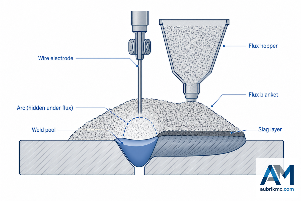
What Is Used to Weld the Sheets of a Wind Tower?
The primary welding process on a wind tower – both for the longitudinal and the girth seams – is submerged arc welding (SAW). With SAW, the arc burns under a blanket of flux that shields against arc flash and spatter while insulating the arc so it can run at high current and high deposition rates.
That high-current, high-deposition-rate quality is what leads the University of Saskatchewan’s fabrication research to note that “the combination of high current and a large deposition rate explains why this technique dominates welding large-diameter linepipe, pressure vessels, and wind turbine towers.” The same deposition-rate advantage carries into longitudinal seam welding on the can, a process sequence documented step-by-step in wind-tower fabrication patent CN106695252A.
There’s no one number for deposition rate, but an actual range. According to the trade journal Fabricators & Manufacturers Association (FMA) Fabricator, the deposition rate of a single-wire SAW machine is commonly up to 40 lbs/hour, and in some cases higher, depending on the wire diameter and polarity. A vendor, LJ Welding Automation, advertises what it says is over 65 lbs/hour for a tandem twin-wire setup that runs two Lincoln Electric ACDC-1000 machines into one common weld pool, paired with a 300-lb heated flux feeder. That’s a vendor performance claim for one specific tandem configuration, not an independently benchmarked industry figure, but it illustrates the productivity gap between single-wire and tandem-wire setups: roughly 60% higher deposition from adding a second wire to the same joint.
| Configuration | Deposition rate | Source |
|---|---|---|
| Single-wire SAW | Up to 40 lbs/hour | The Fabricator (trade press) |
| Tandem twin-wire SAW | 65+ lbs/hour (vendor-rated) | LJ Welding Automation product data |
A 2002 international patent (WO2002038891A1) on wind tower flange fabrication can verify this decision by other means – as they describe how “the ends are welded together after plate is rolled-in. They’re usually welded together by submerged arc welding.” The reason is that SAW is the technology on which virtually the entire class of machines presented in the remaining portion of this guide is based. That’s why nearly all machines presented in the rest of this document are designed to work with the same technique: keep the connection stable, advance the joint uniformly and make sure that the arc remains over the seam for several hours.
Therefore processes such as electric resistance welding, which are widely used with thin-wall pipe in smaller diameters, can’t be used for tower-can thickness while the flux-covered SAW can.
Positioning the Work: Turning Rolls, Rotators, and Column-and-Boom Manipulators
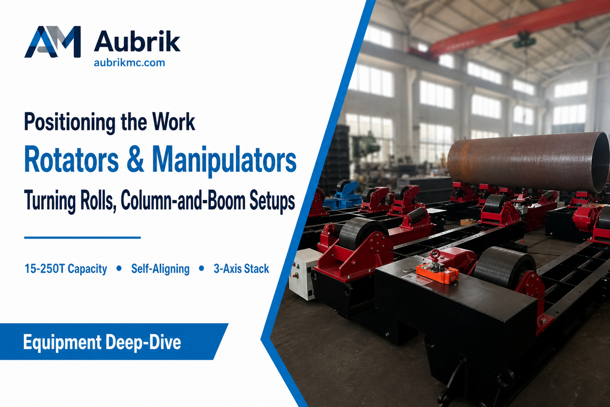
The SAW deposition rate is only effective if the joint move through the arc at a constant rate, at a constant position, for the entire length of the weld. That isn’t something a person can do – a multi-ton tower section can’t be manually turned at a constant speed – so wind tower welding equipment lines separate the task into two distinct machines and two distinct tasks.
Welding rotators (turning rolls) use motor-driven (and often hydraulic-assisted) rollers to cradle the cylindrical tower section and turn it at a controlled rate beneath a stationary or semi-stationary welding head; this is precisely what a US patent filed in 2012 (US20120304588A1) regarding erecting wind turbine towers for horizontal (girth) seam welding depicts: turning the tower on its own axis while it’s welded. Column-and-boom manipulators do the inverse: they support and move the welding torch itself, extending a boom over the turning workpiece to ensure the arc tracks the seam as the section turn.
“In my experience, if it’s that windy the welders have already built hooches to keep warm!”
A structural welding engineer, in a field-welding discussion thread on Eng-Tips
That field remark serves as a good reminder that positioning equipment isn’t only a metallurgical choice: wind loading on the tower section, and on any exposed fabrication setup, is a genuine concern that can dictate whether fabrication occurs inside an enclosed building or necessitates temporary windbreaks around the rotator and manipulator.
What we’re really talking about here’s the 3-Axis Positioning Stack: the rotator, the manipulator, and (on higher production volume lines) a dedicated seam tracker. That’s what separates a wind tower welding line from an average pipe shop; each of the three axes accounts for one degree of freedom, ensuring the SAW head sees a precisely controlled and repeatable joint geometry regardless of the section’s scale. Aubrik manufactures both sides of this stack; the column-and-boom welding manipulator line, for instance, provides the torch positioning component.
Failure to correctly pair these components is an incredibly common and expensive mistake in practice: a rotator undersized by even 20 tons from what the section it is holding requires, or a manipulator with insufficient boom reach, will result in misalignment, evidenced by inconsistent bead width along the seam – an imperfection which usually necessitates rework, removing and re-welding several layers. This is fundamentally a material handling and structural stiffness problem as much as a welding one; a large cylindrical section loaded by overhead crane onto an undersized rotator will flex under its own weight before the arc ever strikes. Aubrik designs its rotator and manipulator lines as integrated units because an imbalanced pairing, not the welding parameters themselves, is typically the underlying cause of most fit-up problems encountered on a wind tower line. ISO 9001-documented tolerance control on both machines is key to keeping multi-ton sections running true through a multi-hour welding cycle.
Longitudinal Seam vs Girth Seam: Two Welds, Two Equipment Setups
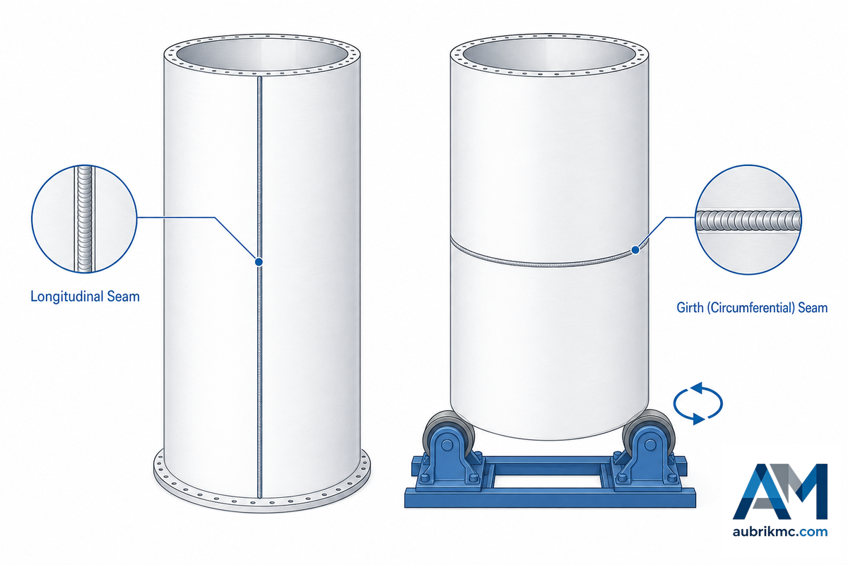
Each tower section will require a separate, sized pair of welds, as the length of one won’t necessarily match the next. Longitudinal seam: runs the length of a single, rolled can, sealing it to make a cylinder. Patent WO2002038891A1 shows exactly this operation – rolling flat stock plate and SAW-welding the two long edges together.
Girth (or circumferential) seam: joins two full cans together, end-to-end, to make a longer piece. The erection-method patent US20120304588A1 suggests this operation uses the weld machine to rotate the assembled cans around the tower’s axis rather than the weld itself traversing a joint.
| Attribute | Longitudinal seam | Girth (circumferential) seam |
|---|---|---|
| Joint direction | Axial (runs the length of one can) | Circumferential (joins two cans end-to-end) |
| Typical stage | Closes a single rolled can | Joins finished cans into a section |
| Core equipment | Fixed or traveling longitudinal seam welder | Rotator/turning roll + column-and-boom manipulator |
| Motion source | Welding head travels along the seam | Workpiece rotates past a near-stationary head |
If you want a deeper dive into girth weld, including fit up tolerance and defect avoidance process flow, Aubrik has its own article focused solely on wind tower girth welding equipment, which assumes that the equipment has already been selected to this category level, unlike this article.
Sizing the Equipment: Capacity, Diameter, and Load Selection
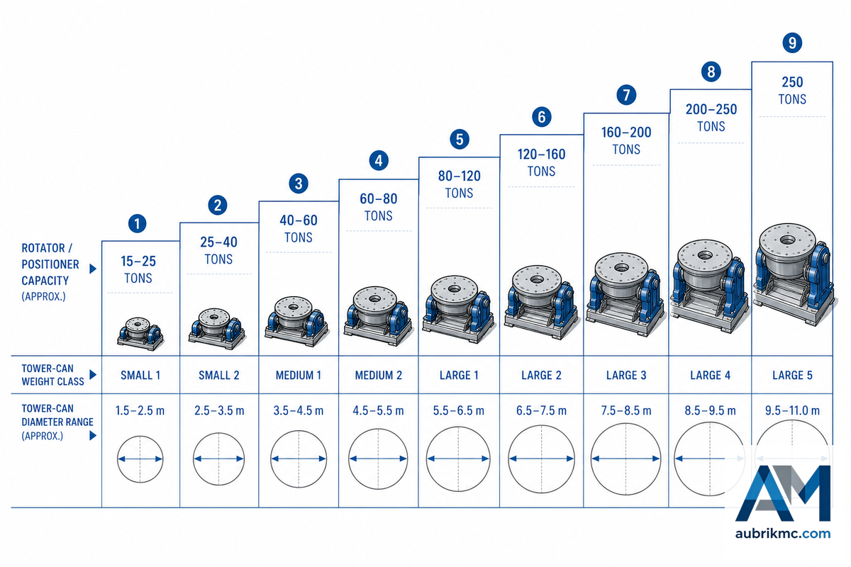
The equipment, termed either a “rotator” or “positioner,” is typically sized by the maximum workload in tons that can be rotated around an axis without slipping.
Catalog data from several unrelated equipment manufacturers indicate the spectrum is quite broad: general-purpose turning rolls list capacity ranges from approximately 15 to 180 tons; turning rolls specifically marketed by Koike Aronson, a major positioner producer, range from 50 to 250 tons; and, specialized wind- tower-only rotators list capacities from a few tons up to 2,000 tons for exceptionally large custom-built systems. This is a market survey range and not a mandated figure based on a welding code.
The 9-Class Tower-Can-to-Rotator Capacity Crossover Curve
Below is a table summarizing estimated wind tower can weight and diameter relative to its relevant rotator capacity category – this information was synthesized from several different vendor equipment listing (including those from Aubrik, made-in-china.com listings, sohowelding.com, lydoer.com, and Koike Aronson’s catalogue of turning rolls). This table represents a helpful first pass in the selection process – use it to narrow down options, but then consult the fabricator’s actual section drawings for final selection criteria.
| Tower Section Class | Approx. Section Weight | Typical Diameter | Rotator Capacity Needed | Positioner Type |
|---|---|---|---|---|
| Class 1 (light) | Under 15 tons | Under 2m | 15-20 tons | Conventional 2-roll |
| Class 2 | 15-30 tons | 2-3m | 30-50 tons | Self-aligning |
| Class 3 | 30-60 tons | 3-3.5m | 50-80 tons | Self-aligning |
| Class 4 (typical base section) | 60-100 tons | 3.5-4.5m | 100-120 tons | Heavy self-aligning |
| Class 5 | 100-150 tons | 4.5-5m | 150-180 tons | Heavy-duty |
| Class 6 | 150-200 tons | 5-5.5m | 180-220 tons | Heavy-duty tandem |
| Class 7 | 200-250 tons | 5.5-6m | 250 tons | Multi-point support |
| Class 8 (over sized/next-gen) | 250-400 tons | 6-7m | 400-500 tons (custom) | Custom multi-point |
| Class 9 (largest custom) | Over 400 tons | Over 7m | Up to 2,000 tons (custom) | Fully custom engineered |
Key Factors to Consider When Sizing a Rotator
- Section weight: shorter base sections with thicker walls can easily weigh more than longer mid sections.
- Overturning moment: dynamic weight combined with eccentric loads or rotation of the weld welding head will induce forces that the rotator must resist.
- The range of sizes available for roller beds vs. actual can diameters for different sections of the tower. Base sections are usually the widest.
- Room to grow: Some manufacturers now make rotators capable of handling sections in excess of 36 meters, so it might be wise to invest in equipment with room for your project’s growth rather than needing to purchase a new set of rotators in the near future – the U.S. Department of Energy notes towers keep getting taller as turbine diameters continue to grow.
⚠️ Important
Don’t let wall thickness be an easy cost-reduction target. The “academic fatigue analysis of welded wind turbine tower connections” published by Welding in the World in 2024 (corroborated by an American Journal of Engineering and Applied Sciences finite-element study of two 76.15m towers) showed that roughly a 20% reduction in shell-wall thickness led to a 50% to 70% loss of fatigue life at the specific welded detail modeled-not a linear relationship. (The precise percentages vary by tower height, weld detail and load cases modeled, but the principle remains: thin walls cost significant life.) A relatively minor savings of material during design can result in a large loss of life at the weld.
Standards and Weld Verification: AWS D1.1, IEC 61400-6, and NDT
There’s no universal welding code that governs wind tower welding-it all depends on the place of manufacture, installation site and specific type of certification being obtained. In the United States, weld procedures and inspection for structural steel, including wind tower fabrication, is typically done to American Welding Society (AWS) D1.1/D1.1M, Structural Welding Code-Steel. (As of this writing, the latest version is the 2025 edition: D1.1/D1.1M:2025-AMD1, as listed in the AWS’s standard record.) A firm that specializes in welding inspections for the wind-energy sector “strongly recommend the inspection to be in accordance with AWS D1.1, EN 1090 or IEC 61400-1, since this applies to all locations.” Notice the variety of applicable codes – a U.S. Bureau of Safety and Environmental Enforcement fatigue design review of offshore wind turbine generator structures illustrates just how much the applicable structural-integrity standard can vary by installation type and location.
That variety can make a big difference. IEC 61400-6:2020+AMD1:2025-Wind energy generation systems-Part 6: Tower and foundation design requirements (with AMD1 as of June 2025), issued by the International Electrotechnical Commission, is the standard specifically written for structural integrity of wind turbine towers and their foundations, covering everything from geotechnical analysis to flange connection strengths. It’s not a welding execution code in the same way as AWS D1.1; rather, it defines the design criteria against which welding execution codes such as AWS D1.1 and EN 1090 must comply. Meanwhile, the European Commission’s own Construction Products Regulation FAQ explicitly states that wind turbines and their towers “fall outside the scope of EN 1090-1 and therefore can not be CE marked in accordance with the Construction Products Regulation. The conformity assessment process must be carried out in accordance with [the] Machinery Directive and case by case.” Assuming “AWS D1.1 handles it” for a tower to be installed in the European market is a mistake.
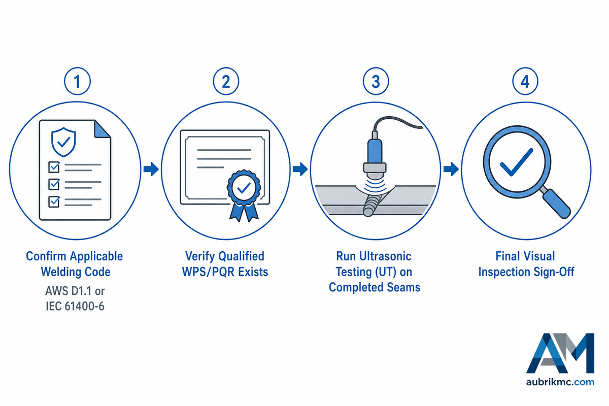
Standards define what a weld should do; NDT confirms that it did. We’ll call the sequence an AWS D1.1-to-NDT Verification Field Manual: (1) establish what structural code the tower’s target market uses, (2) confirm a qualified WPS/PQR is in place prior to production welding begins, (3) ultrasonically test all finished girth and longitudinal seams, looking for internal flaws such as porosity or incomplete fusion, all without cutting the joint apart, and (4) record results against the governing code’s acceptance criteria (AWS D1.1 or its applicable regional equivalent). Our own lines are designed and certified to ISO 9001 and CE standards, setting a fabricator’s base-line quality control level upon which a local weld procedure qualification will build.
Manual vs Automated: The Equipment Investment Case
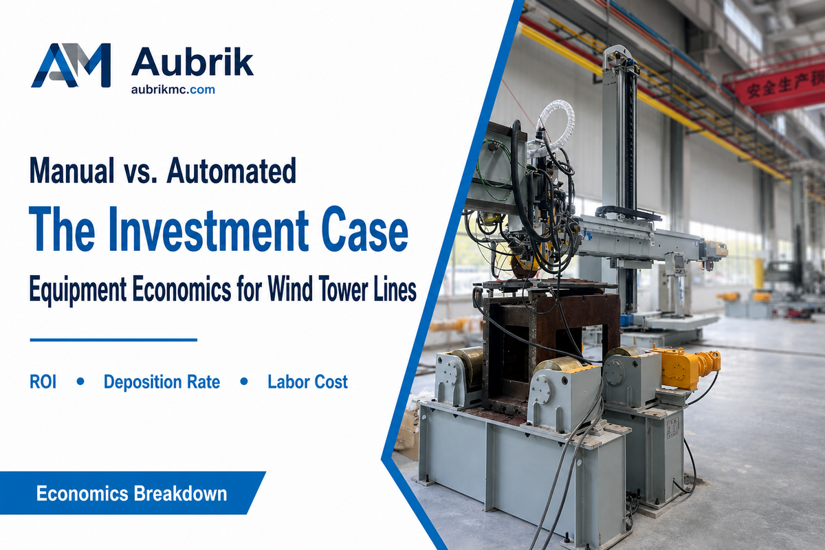
An honest answer here isn’t “automation is better” but rather a trade-off between flexibility and consistency. A 2025 open access study in Discover Materials (Springer) actually compared manual to automated welding on a linear welding robot across different materials thicknesses. As expected, the manual method performed better on flexible, variable shapes while the automatic delivered superior accuracy and consistency on consistent joints and decreased overall welding time by nearly 40% relative to manual. While that experiment didn’t use a specific wind turbine-application SAW setup or provide wind-turbine-specific time savings data, it clearly illustrates the flexibility vs consistency balance facing a wind tower fabricator when deciding between manual rotators and automated manipulator/SAW/seam-tracker systems.
✔ Advantages of Automated Lines
- Consistent weld parameters over long production runs – more cost-effective than an arc welder run manually pass after pass
- Reduced operator time on repetitive, high-heat-input passes
- Real-time deposition-rate and heat-input monitoring on modern PLC/HMI-controlled systems reflecting advanced welding technology
- Lower exposure to overhead-welding and heat-related fatigue risk for crews
⚠ Limitations to Weigh
- Less adaptable to irregular fit-up or non-standard geometry than a skilled manual welder
- Higher upfront equipment cost and a commissioning/programming period
- Still requires a qualified welding operator to set and verify parameters, not a “hands-off” system
Given many fabricators are already employing robotic welding systems elsewhere in the facility, adding automated wind tower capabilities often involves more of an upgrade to existing welding automation systems and software than a from-scratch build (PLC/HMI and quality-monitoring platforms typically can transfer from other automatic welding projects, even if the physical manipulator hardware doesn’t).
Keeping the Line Running: Equipment Maintenance and Uptime
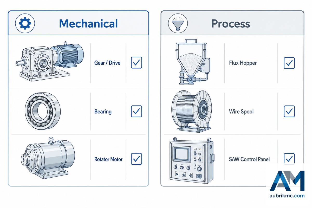
Maintaining wind tower welding equipment comes down to two different, yet easily confused, types of upkeep: mechanical (rotators, manipulators, drives) and process (SAW system parameters) – the same dedicated-equipment split described in fabrication patent CN106695252A. Skip either one and downtime follows – just at a different stage of the production cycle.
- Inspect rotator drive gears, rollers and bearing surfaces periodically-a slipping roller, for example, can cause rotational speed to vary during the weld.
- Check manipulator boom and column alignment – any deviation results in inconsistencies in the torch stand-off along a long girth seam.
- Monitor flux for contamination and consistent feeding. The most common-and often undetected-source of SAW porosity isn’t mechanical.
- Periodically recalibrate the system’s heat-input and travel-speed set points to correspond to your qualified WPS-don’t just wait until after you find a defect, as parameters can drift slowly before you can actually see a problem.
- Keep sensors andseam-tracker optics clean. Blocked optics are a known failure point in dusty outdoor fabrication areas where automated equipment is commonly used.
Industry Outlook: Robotic and Sensor-Integrated Welding Automation
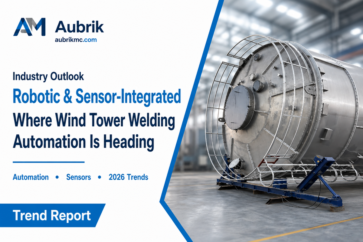
wind tower manufacturing discussions across the tower industry – both onshore wind and offshore wind segments – have increasingly gravitated toward a single choke point. The claim is that the constraint is the availability of welding automation equipment and not crane capacity or the upstream supply chain of steel that hinders tower’s rate of output. That specification is significant because, rather than saying “the industry is automating,” the equipment specification dictates the buyer’s most important long-lead item that this guide addresses (rotator size, manipulator’s capability, and SAW speed) – the same welding-focused innovation trend a Northeastern University-backed tower project earned Time Magazine recognition for in 2023.
Behind that promise, the welding technology roadmap is straightforward: sensor-integrated systems that measure real-time arc stability, joint fit, and travel speed are rapidly graduating from pilot to spec-equipment status, and at least one welding-robot vendor claims its automated systems reliably weld 50-meter tower seams in sub-zero, windy Arctic climes where manual teams reach hard physical safety-and welding-limits. For the sake of background context (this isn’t the core point): analysts expect the larger wind turbine automation space to grow at a >25% compound annual rate until about 2035 and the broader arc welding equipment space to grow at a high single-digit clip; useful contextual data points, but they don’t substitute for the underlying equipment trend they reflect. For anyone budgeting a 2026-2027 tower line expansion, the punchline is this: spec sensor-integrated on new rotator/SAW purchases today, rather than planning it as a post-installation retrofit.
Delaying that transition involve another, potentially hidden cost: fabricators who are stuck on manual lines report that their gap with automated producers (productivity is an identifier code used in the industry for these machines, not a specific brand) is widening, and that a single day of lost production on a 100-ton line alone will often outweigh the sensor investment – effectively turning the automation decision into a question of cost, not technology. For those customers that are looking to retrofit, Aubrik has put real numbers around that gap, since often it’s not the broad market-size numbers quoted in the press above that’s driving the discussion, but rather what bottleneck they’re struggling to break today on any given line.
Frequently Asked Questions
Q: Are wind turbine towers welded, or bolted/cast?
View Answer
The primary industry standard for constructing wind turbine towers for the commercial market is welded steel, not cast or bolted, construction of the actual tower section tubes. Bolted flanges joining complete segments are fairly common but welded is generally preferred to connect individual cans, (or bodies) of each section together – as a result of their wall thickness, usually with submerged arc welding. For extremely high buildings however concrete and composite steel-concrete towers are generally employed but steel welded ones continue to lead.
Q: What is submerged arc welding and why is it used for wind towers?
View Answer
submerged arc welding (SAW) operates his welding arc under a bed of granular flux instead of the atmosphere. That blanket allows him to operate at higher currents with reduced spatter and no visible arc flash. The reduced spatter and lack of arc flash enables higher deposition rates compared to an open arc process like stick or MIG welding of comparable plate thickness.
The wind tower plate is usually high-strength, thick structural steel and the combination of high deposition and uniform penetration allowed SAW to become the industry standard for the longitudinal and girth seams on tower sections, not some faster but shallow process.
Q: What size welding rotator does a wind tower section need?
View Answer
Depends on the actual weight and diameter of the section-there’s no single industry-wide standard. The base tower sections – normally the heaviest and largest section of the tower- tend to lean toward the high end of the 15-250 ton rotator capacity rating ranges you’ll see in various equipment listings by independent vendors-and the thinner top sections will require much less. As a rule, it’s safer to size against the heaviest section you anticipate ever having to lift, with some buffer against overturning moments, rather than just total weight, and to check that the rotator’s roller-bed size range includes your smallest and largest cans.
Q: How is a wind tower weld inspected for quality?
View Answer
A wind tower welds will usually be checked using a visual inspection, combined with some form of non-destructive testing (NDT) to ensure no internal flaws like lack of fusion or porosity are present in the joint without physically having to slice it open – typically that means some type of ultrasound test. The limits on what’s deemed to be an acceptable weld will usually be defined by the structural welding code for whatever country the tower is being constructed for or is going to be sold in. So for the US this means the code to check for would be AWS D1.1.
In other countries this might be some regional equivalent code and again that’s why finding out what code applies is as important to you as how Hohupwill test the finished work. The expectation will be that a fully vetted welding procedure specification (WPS) will have already been generated via procedure qualification records (PQR), and your job is to simply ensure that the production welds adhere to that WPS.
Q: Can existing manual welding lines be retrofitted for automation?
View Answer
In many cases, yes-a manual rotator-and-manipulator setup may well be augmentable in stages-starting by installing a PLC-based deposition-rate and heat-input monitoring function atop the mechanical hardware prior to retiring the rotator or the manipulator. Complete retrofits are trickier when a prior generation of rotator does not accommodate the tonnage capacity or the range of roller-bed diameters appropriate for current sections. An existing line’s tonnage capacity that may have served well for an older turbine may not possess sufficient tonnage capacity to handle the new generation of wide towers that feed the current generation of large turbines.
Auditing the capacity and geometry of the line now-it would seem, is the correct way to begin-before taking the first step.
Q: Is SAW the only process used anywhere on a wind tower?
View Answer
No. The structural seams are the principal application for SAW, but the flange attachments, welding of interior components, and repairs might use a flux-cored arc welding (FCAW) or a shielded metal arc welding process.
Why We Write This
Aubrik (Wuxi ABK Machinery), founded 1999, produce the welding positioners, rotators, manipulators, H-beam assembly machine lines, and complete turnkey wind tower production lines which were delivered to over 20 countries in the world under ISO 9001 and CE marks, supporting welding jobs and technical training in every market served.
The guide is produced using not only our product information, but also standards documents, patent applications, and independent commercial and academic information – since any purchase candidate comparing the wind tower welding equipment also need to know how welding automation works in practice, not just on a spec sheet.
References & Sources
- AWS D1.1/D1.1M:2025-AMD1, Structural Welding Code, SteelAmerican Welding Society
- IEC 61400-6:2020+AMD1:2025, Wind energy generation systems, Part 6: Tower and foundation design requirementsInternational Electrotechnical Commission
- Construction Products Regulation, Frequently Asked QuestionsEuropean Commission
- The effect of submerged arc welding parameters on the properties of large-diameter structuresUniversity of Saskatchewan
- Improving Deposition Rates with Submerged Arc WeldingThe Fabricator
- An Analysis of the Efficiency and Accuracy of Manual and Autonomous Four-Wheeled Linear WeldingDiscover Materials (Springer, 2025)
- Welded Connections of Wind Turbine Towers Under Fatigue LoadingAmerican Journal of Engineering and Applied Sciences
- Evaluation of the Fatigue Resistance of Butt-Welded Joints in Wind Turbine TowersWelding in the World (Springer, 2024)
- Time Magazine Names Northeastern Research-Supported Company’s Turbine Towers to Best Inventions of 2023 ListNortheastern University College of Engineering
- CN106695252A, Method for Manufacturing Main Body Structure of Wind Turbine TowerGoogle Patents
- US20120304588A1, Method for Erecting a Wind Turbine TowerGoogle Patents
- WO2002038891A1, Flange with Cut for Wind TowerGoogle Patents
Related Articles
- Wind Tower Girth Weldera deeper look at girth-weld fit-up and defect-avoidance workflow
- Wind Tower Production Linehow the full equipment stack fits into one production line, including capacity planning and compliance staging
- Robotic Welding Cell: The Complete Guidefor shops evaluating robotic cells outside the wind tower category
- Cobot Welding: The Complete Guidecollaborative robot welding for lower-volume or mixed-part fabrication
- Welding Positioners and TurntablesAubrik’s broader positioner line for non-tower cylindrical and irregular workpieces