Get in Touch with Aubrik Company

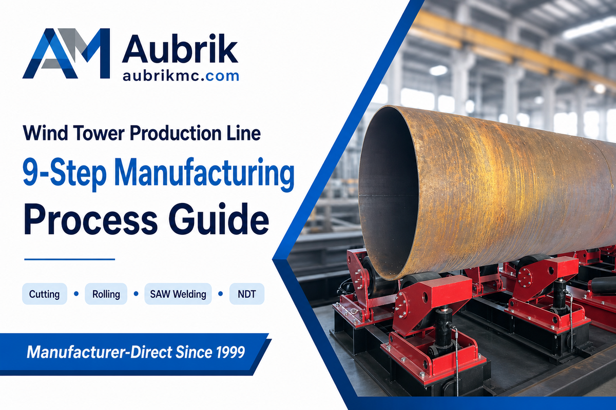
In short. A wind tower production line is the integrated system of cutting, rolling, welding, inspection, and coating stations that turns steel plate into finished turbine tower sections. The stage sequence is fairly standard across vendors, but the equipment tier, automation level, and line philosophy you choose change cost and output far more than any single machine spec, and almost no vendor page will tell you which choice fits your actual order book.
Quick Specs: Wind Tower Production Line at a Glance
Core Stages Plate cutting, rolling/forming, longitudinal welding, circumferential/fit-up welding, NDT, coating Primary Welding Process Submerged arc welding (SAW), plate up to 5 in. (127 mm) thick Onshore Tower Range 1.5-5 m diameter, 15-60 mm wall thickness, up to 100 t/section Offshore Tower Range 3-7.5 m diameter, 18-80 mm wall thickness, up to 300 t/section Line Philosophy Choices Job-shop flexible vs. dedicated high-volume; manual vs. semi- vs. full automation
That equipment chain makes flat steel plate into a finished turbine tower section, and the broad workflow is roughly the same whether a fabricator buy it from China, Europe, or the US. What differs-and what almost every vendor page omits-is which step in that workflow limits your output, and whether the automation level a salesperson is pushing truly matches your actual order mix. This guide is from an independent, vendor-neutral perspective; all process figures herein are drawn from published engineering literature, the trade press, and peer-reviewed academic studies, rather than from any single manufacturer’s claims.
- Doubling the capacity of a downstream assembly step increased output by less than 2% in one reported case-because the actual bottleneck was upstream plate rolling.
- peer-reviewed research indicates that going “fully automated” may not be the cost-effective choice; a relatively simple lean manufacturing improvement cut one factory’s lead time by 30%
- The most critical difference in offshore isn’t just increased scale, but assembly and storage in bundles for months on port quaysides, a load case usually neglected by standard production planning.
- Robotic welding isn’t yet able to self-detect defects; automated real-time defect detection remains a subject of active 2024-2025 research rather than a solved problem.
What Is a Wind Tower Production Line?

A wind tower production line is a series of dedicated fabrication stations-cutting, rolling, welding, inspection, and coating-all designed to transform steel plate into cylindrical or conical tower sections consistently. Purpose-built lines, whether Chinese, European or American, share the same basic stages: cut and bevel the steel, roll it into a cylindrical shape, weld the longitudinal seam, join the cylindrical sections together with circumferential welds, inspect, and coat.
💡 Key Takeaway
The production line exists to remove exactly the type of hidden capacity loss that reveals itself once a fabricator is locked into a contract for more sections than can be delivered, by making that basic nine-step process a repeatable one. Its primary goal is not to hit a single, impressive-sounding headline output rate, but to provide whatever level of throughput is required by the customer.
Wind tower manufacturing is inextricably tied to the broader build-out of renewables and is less influenced by an independent production equipment cycle than the growth trend of the wind power industry and broader wind energy sector itself. A manufacturer considering a new line is ultimately purchasing not just equipment but a strategic position in a rapidly evolving supply chain, which is moving toward increasingly large and heavy turbine sections as energy producers strive for greater capacity per turbine.
The 9-Step Fabrication Process Industry-Wide

The nine-step sequence-which can be viewed down to the individual station level, regardless of automation level-is standard across all wind turbine tower production lines, and detailed parameters are publicly documented in industry standards and peer-reviewed scientific literature rather than marketing materials.
| Step | Typical Equipment | Published Parameter |
|---|---|---|
| 1. Plate cutting | CNC plasma or gantry cutting machine | Cuts steel plate up to 5 in. (127 mm) thick to size before rolling |
| 2. Edge preparation | Beveling/milling station | Bevels the plate edge to the angle the SAW procedure specifies, ahead of rolling |
| 3. Plate rolling & forming | 3-roll or 4-roll plate rolling machine | A single dedicated machine (2-3 shifts/day) can roll roughly 6,000 conical sections/year, each formed in under 30 minutes |
| 4. Longitudinal seam welding | Submerged arc welding (SAW) head | One 2025 peer-reviewed study reports a parameter window of approximately 390-400 A, 26.5-28 V, 363-390 mm/min travel speed, 1.8 kJ/mm heat input for S355G10+M offshore-grade steel |
| 5. Fit-up | Fit-up rotator, laser alignment station | Aligns adjacent cans before circumferential welding to hold root-gap tolerance |
| 6. Circumferential welding | Column-and-boom manipulator, girth welder | Cans joined via cantilever or gantry-mounted SAW along circular seams |
| 7. Non-destructive testing (NDT) | Ultrasonic testing (UT), visual inspection | One documented line reduced UT sampling from 100% to 20% of welds as process confidence grew |
| 8. Surface preparation | Sandblast booth | Removes mill scale and roughens the surface profile ahead of coating |
| 9. Coating & finishing | Automatic paint line | Multi-layer anti-corrosion coating applied before internals (ladders, platforms, cabling) are installed |
Edge prep at the very start carries the rest down the line. Having a good angle on the plate bevel set you up for successful longitudinal and circumferential welding of the seams and eventually the flange welds without having to add lots of extra fill passes.
Many large production tower manufacturing lines that are designed for mass tower welding actually run a completely separate (physically separated) welding line for the outer welding pass of a circumference vs the root pass for the inner diameter, because the location becomes so different once you have the cans joined. It’s this unique combination of circumferential and longitudinal welds that really sets tower welding apart from other forms of flat plate welding structural steel, and that some suppliers of submerged arc welding systems geared to other markets can miss.
📐 Engineering Note
The approximate SAW parameter window above (390-400 A, 26.5-28 V) is as reported in a single 2025 peer-reviewed study on S355G10+M offshore wind tower steel, cross-checked against ISO 10360-8 dimensional tolerances; treat it as directional pending your own WPS qualification rather than a universal setpoint. If a vendor quotes welding parameters far outside this window for the same steel grade, ask them to show the qualification record, a wide gap usually means an unverified procedure, not a proprietary advantage.
The following two examples illustrates why sequence is far more important than a station’s speed rating:
- A wind tower fabricator documented in trade press that cut the rate of UT sampling of welds from 100% to 20% didn’t cut the sampling rate until it had sufficient process confidence in its upstream cutting and rolling processes; if it had cut it prior to developing confidence, defect risk simply shifted downstream rather than vanished.
- A 2026 discrete-event simulation of an actual wind-tower fabrication facility showed that when they quadrupled the number of parallel assembly (“grow”) lines from two to four, annual output hardly budged-it was still around 36-40 sections/year-since the bottleneck was really the capacity upstream, of the plate-rolling and rework station. When the simulation was revised to also increase capacity of the rolling station, the output soared to more than 60 sections/year. It’s that simple.
More welders don’t help when rolling is the problem.
What to Look For in Core Line Equipment, A Buyer’s Checklist
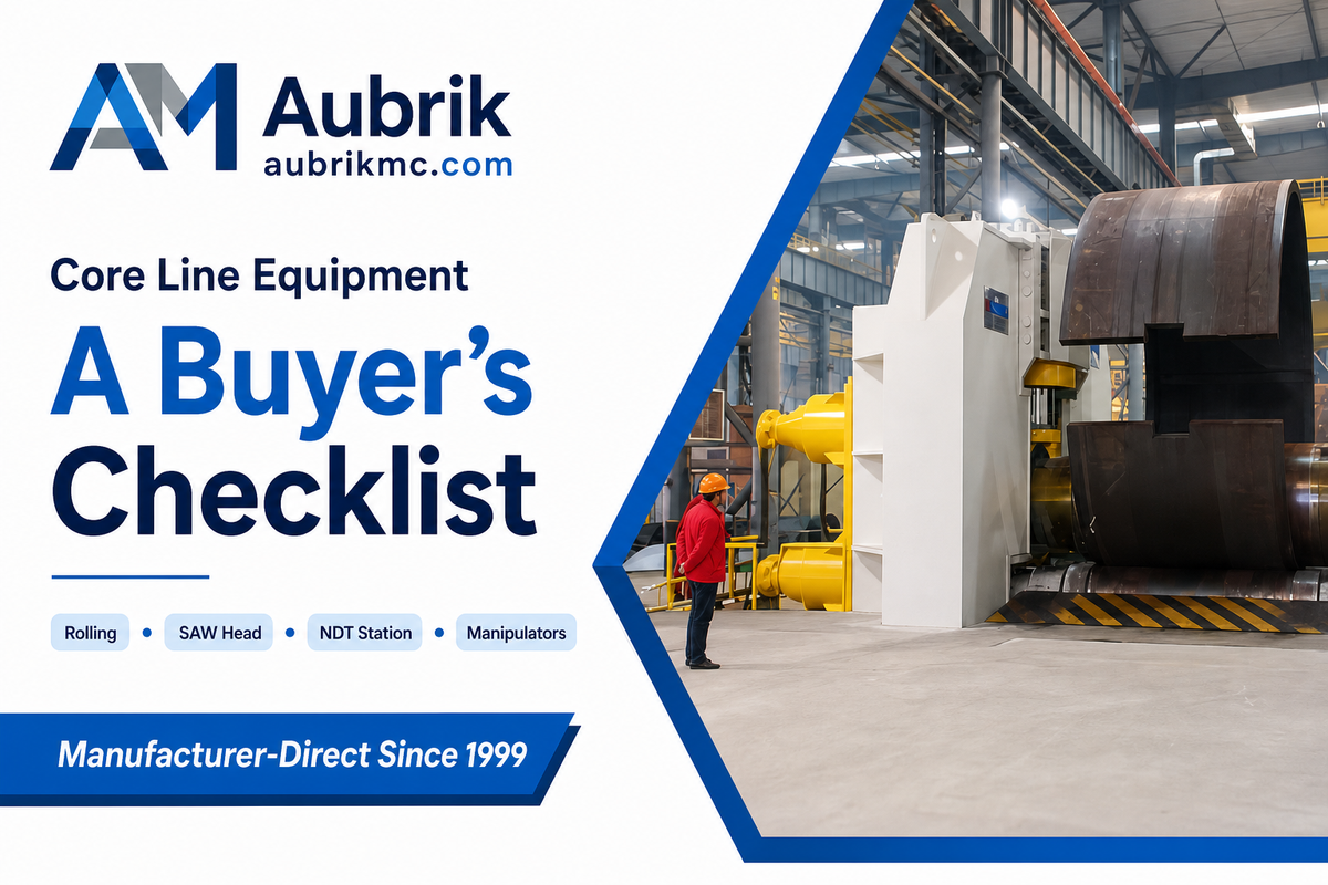
Instead of explaining what each station will achieve in broad strokes, we cover what you’ll want to know about it before you agree on the hardware for your tower welding production line. That means checking real throughput numbers, verified weld parameters, and documented capacity limits for each station instead of marketing claims, since the six equipment questions below are the ones a signed contract can’t undo.
| Station | Question to Ask | Red Flag |
|---|---|---|
| Plate rolling machine | What’s the actual annual section throughput at your target plate thickness? | Only a “max capacity” figure, no realistic multi-shift number |
| SAW welding head | Can you show the qualified parameter window (amps/volts/travel speed) for our steel grade? | Parameters quoted without a qualification/test record |
| Fit-up weld rotator / positioner | What tower diameter range and section weight does it actually handle? | Vague “handles all standard towers” without a stated range |
| Welding manipulators (column-and-boom) | Can the boom reach all weld positions without repositioning the whole unit? | No stated reach/coverage envelope for your section length |
| NDT station | What’s your actual UT/visual sampling rate, and why? | No documented sampling-rate policy at all |
| Overall line capacity claim | Which single stage sets that ceiling number? | A capacity figure with no bottleneck stage identified |
That bottleneck question isn’t abstract. Evidence comes from a recently announced new piece of equipment: WO2025122118A1 is an alignment-and-welding patent application (filed 2025) covering a hollow annular flange joint to connect sections of tubular towers-equipment-level engineering in this domain is still moving, suggesting that “Our list of equipment hasn’t changed in a while” isn’t necessarily the compliment a supplier wants.
The CNC cutting station deserves the same scrutiny as welding: ask whether the machine can be customized to your specific plate-thickness range without a separate capital purchase, and whether “high-quality cut edge” means a stated bevel-angle tolerance or just a marketing adjective.
What Is the Structure of a Wind Turbine Tower?
The structure of the tower itself is composed of several successive sections or tubular, cylindrical or conical, steel “cans” bolted to each other by welds around their circumference and each terminating in flanges at the joint lines, with internally fitted access ladders, service platforms, and wiring runs built into each section.
Each section also includes a reinforced door on a service module, positioned to prevent the stress concentration that an aperture would otherwise create on an uninterrupted tube. The volume of these structural components scales with height, so a 60-meter onshore section carries considerably fewer of them than a 150-meter offshore section.
How Do You Produce Wind Tower Flanges?
Tower flanges are cut, rolled to the tower’s ring diameter, and joined by flange welding to each section end, then carried through post-weld heat treatment and precision drilling for the bolt pattern that connects adjacent sections on site, a sequence most vendor pages skip over entirely.
Flange runout – how far the flange face deviates from true flat – is a structural tolerance, not a cosmetic one, because heat-induced distortion at this joint concentrates bolt-fatigue stress that has been linked to documented tower failures. A 2025-filed patent for a hollow annular flange connection design (WO2025122118A1) signals that flange-joint engineering is still an active area of improvement, not a settled detail.
Job-Shop Flexibility vs. Dedicated High-Volume Line, Which Setup Fits Your Order Book
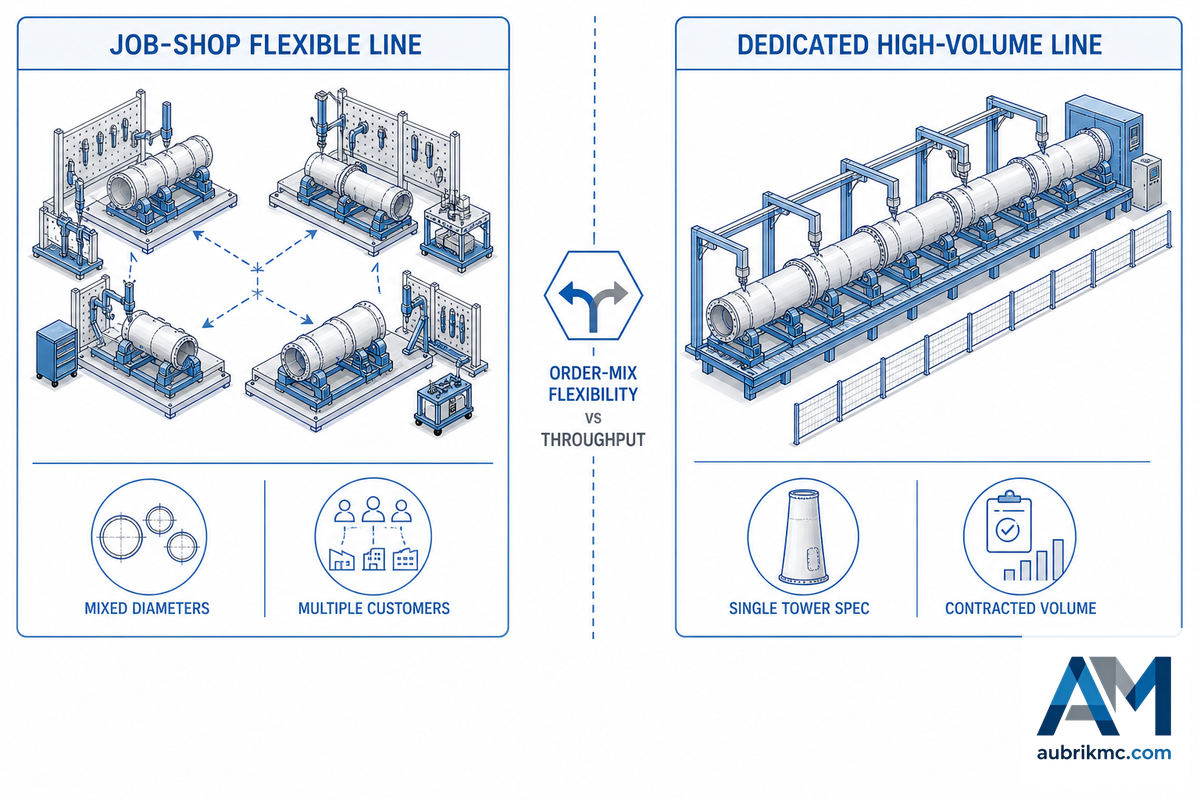
The most consequential production-line decision isn’t which brand of welding head to buy – it’s whether your line should be configured for order-mix flexibility or single-spec volume, and vendors rarely frame the choice this way because a flexible recommendation doesn’t fit neatly into a single equipment quote.
Configuration Decision Framework
- Mixed diameters, multiple customers, unpredictable order timing → prioritize a job-shop-flexible line with modular, reconfigurable fit-up stations over a fixed-geometry dedicated line.
- Single tower spec, contracted multi-year volume, predictable cadence → a dedicated line tuned to one geometry, like a purpose-built Aerisyn-style setup, gets more throughput per dollar than a flexible line running the same job repeatedly.
- Growing order book, uncertain future mix → favor modular workstation expansion (add stations without a shutdown) over a full-capacity rebuild committed to today’s mix.
Two independent, peer-reviewed sources back up a genuinely counterintuitive point here: automation isn’t automatically the right answer to a capacity question. One study concludes that “increasing automation requires large, expensive, and specialized equipment that may not always be economically viable” for wind turbine manufacturing. Separately, an action-research case found that basic lean-manufacturing tools – 5S, Kanban, standard work – cut lead time and raised throughput without any capital automation spend at all, directly contradicting the common assumption that scaling capacity require automation investment.
One more case shows the same lesson from a layout angle rather than an automation angle: one factory that switched from batch processing to a cellular, U-shaped station layout cut lead time from 10 days to 7 (a 30% reduction) and raised monthly output from 3 towers to roughly 4.3 towers, a 43% productivity gain achieved through process reorganization, not new equipment.
Steel, Concrete, or Lattice, How Tower Structure Type Changes the Line
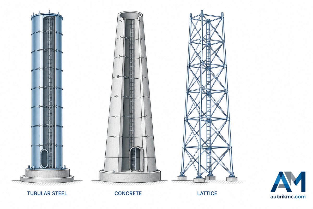
Most production lines in this market are built exclusively for tubular steel towers, because steel, concrete, and lattice structures don’t share equipment. One engineered around plate rolling and circumferential SAW welding has no direct use for precast concrete segment forms or lattice-member bolting jigs.
✔ Tubular Steel — Advantages
- Standardized fabrication process shared across most global manufacturers
- Highest section length achievable per piece before transport limits kick in
- Mature SAW/NDT quality-verification pipeline with published parameter windows
⚠ Steel — Limitations
- Onshore tower diameter capped near 4.3 m by road-transport constraints in most markets
- Ultra-tall (140 m+) steel towers require special-transport logistics beyond standard fabrication capability
Concrete and hybrid concrete-steel towers exist specifically to route around the steel transport-diameter ceiling: precast concrete segments from a leading German manufacturer are limited to roughly 2.8 meters in section height purely by transport mass and size constraints, which is why some ultra-tall tower projects turn to on-site 3D-printed concrete bases instead of trucking taller precast sections. Lattice towers remain a minority structure type, generally reserved for smaller turbines or markets where steel-plate supply chains are less developed.
How Many Types of Wind Turbine Towers Are There?
Nearly all towers fall into one of three types of structures: tubular steel (the great majority of installed towers), concrete precast and cast-in-place (growing for ultra-high hub heights) and concrete-steel hybrid towers (combining a concrete lower and steel upper portion). Lattice towers comprise a much smaller remaining portion, most often associated with older and smaller installations. Production for a specific type of structure isn’t interchangeable on a single production line without changing core forming and joining machinery.
Onshore vs. Offshore, Why Tower Size Requirements Are Diverging

The design problems are becoming more disparate with increasing size Offshore and onshore towers are no longer just scaled versions of each other – they’re diverging engineering problems, and the gap is only widening as offshore turbines scale up.
| Factor | Onshore | Offshore |
|---|---|---|
| Section diameter | 1.5-5 m | 3-7.5 m (up to 10 m design ceiling for 22 MW-class reference turbines) |
| Wall thickness | 15-60 mm | 18-80 mm (monopile foundations to 150 mm) |
| Section weight | Up to 100 t | Up to 300 t (monopiles to 2,500+ t) |
| Capacity factor | 33-39% | 50-60% |
| Levelized cost of energy | $34-49/MWh | $79-100/MWh |
Onshore towers are typically capped at a diameter near 4.3 meters for reasons completely unrelated to welding capacity — clearance under road overpasses and bridges — and the problem constrains U.S. average installed hub height to around 90-103 meters, despite the fact that a more efficient tower of 140 meters could add more than 21% of electricity production versus a 80 meter tower. Offshore towers don’t face that limitation as they’re delivered by ship and not truck, which is precisely why the specifications for offshore tower diameters and wall thicknesses have expanded so much more rapidly than their onshore counterparts as turbines in the offshore wind energy segment head towards 20 MW.
Onshore-vs-offshore divergence doesn’t stop at final tower geometry. Offshore towers are typically pre-assembled and stored in close-proximity groups on port quaysides for extended periods before installation, a peer-reviewed 2023 study modeling 115-meter towers found this staging arrangement creates its own aerodynamic and structural load case on the quayside’s foundations, distinct from the tower’s final in-service loads. Sizing a line only for fabrication throughput, without accounting for downstream port staging capacity, can create a bottleneck the fabrication numbers never predicted.
What to Verify Before You Commit to a Production-Line Vendor

Every supplier doesn’t offer the same quality assurance for wind farm fabrication, and the difference between a well-run line and a corner-cutting one usually only surfaces after a contract is already signed. The following questions aren’t questions a supplier’s marketing pages will answer spontaneously – they’re the direct questions you must ask before committing capital to a vendor relationship that will run for years.
- Request to attend and receive the Factory Acceptance Test (FAT) report prior to shipping.
- Inquire as to the specific standard governing cutting, welding, NDT, coating and other individual process steps rather than asking to see certifications for a group of processes.
- Ask for the lead time band for your specific capacity tier, rather than a general lead time estimate.
- Find out the location of stocked spare parts and the lead time to deliver to your facility should an station fail.
- Discover the vendor’s procedure in case of a supply chain disruption with its sub-contractor — documented risk with a supply chain scattered among multiple sub-vendors has contributed to delays in multiple wind tower projects.
⚠️ Important
A percentage-based figure with an unreferenced methodology is often seen on production line marketing pages in this space. Treat a “60% cost reduction” or “99.8% quality consistency” claim without a stated measurement method as directional.
Running an Automated Line, the Operational Side Vendors Don’t Advertise

While much is written about the speed of automation, the practical, day-to-day realities are often overlooked.
65+ lbs/hr
Tandem SAW deposition rate on a dedicated growing-line system
6,000/yr
Conical sections one dedicated rolling machine can produce running 2-3 shifts
0.92 AUC
Best published 2024 result for automated multi-modal weld-defect detection — not yet a solved problem
This last figure is more important than it might seem. Robotic and automated welding stations don’t naturally verify their own weld quality: “robots currently don’t have the capability to detect welding defects” introduced during welding, and reliable, multi-modal (audio + video) defect detection across multiple defect types remains a research challenge, not a standard industry practice, according to a 2024 paper on real-time robotic weld-defect detection. Take any vendor claim that automation “guarantees” weld quality as a claim about throughput, not verification – the non-destructive testing (NDT)/inspection step still has to catch whatever the robot itself missed.
One documented result shows what a well-run automated line can achieve on the metrics that matter most to a buyer: one customer’s line went from producing 8 sections per month to 32 per month after moving to an integrated automated setup, with weld qualification rates rising from 88% to 99.2% over the same period, according to Aubrik’s own published case data. That’s a real, attributable result from a single vendor relationship, worth knowing as a benchmark, not as an industry-wide guarantee, since results depend heavily on the specific line configuration and staffing model behind it.
Staffing is the piece vendors skip over almost completely in their brochures. Changing from one tower diameter to another on the same automated line requires a physically reconfigured fit-up tooling, and operators still need training on what to catch that automation doesn’t – a “finicky” weld joint variability that one automation specialist’s own testimony indicates may be preventing some welds from becoming fully automated even on high-end machines.
Who Builds These Lines, A Quick Industry Landscape

Two general categories comprise this market. Tower manufacturers and tower fabricators own and operate their own production lines for the purpose of making tower sections as the finished product for wind turbine manufacturers (turbine OEMs) and project developers.
Equipment and automation integrators sell production lines and services to wind tower manufacturers – cutting, rolling, welding, NDT equipment – who operate the lines themselves.
- Tower manufacturers: Sell finished tower sections to turbine OEMs and project developers.
- Equipment/automation integrators: Sell production lines – but not finished towers – to firms who are building or expanding their own manufacturing capacity.
Recent capacity expansion spans both categories as the wind industry continues to grow: A U.S. large-scale, dedicated offshore-wind steel fabrication plant planned will support 500+ jobs across 90 acres and further investment in specialized facilities for offshore needs. Whether you’re working with the first category or second, the equipment verification and vendor due-diligence considerations above still apply- whether a fabricating facility’s in-house production line or a purchased, fully turnkey operation lives or dies is fundamentally based on identifying its bottleneck.
Industry Outlook, The Repowering Cycle and Growing Tower Sizes
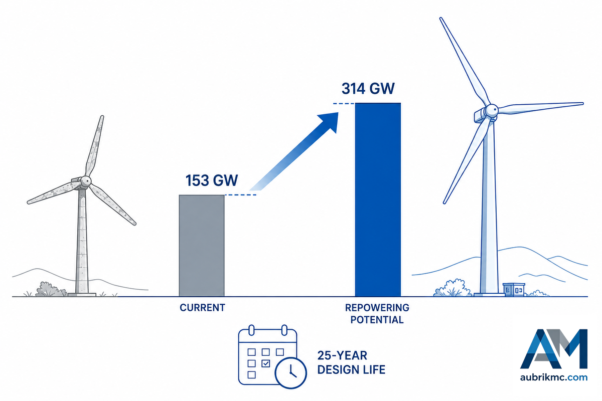
Not so much market-size forecasting, but a structural fleet-age problem is currently the primary driver for new production line investment. In both the U.S. and Europe, many wind farms built in the 1990s and 2000s are approaching, or are past, the 20-40-year fatigue design life of their turbines; a 2026 peer-reviewed analysis estimates that repowering U.S. onshore wind alone could increase total capacity more than twofold, from the existing 153 GW to approximately 314 GW.
153→314 GW
U.S. onshore repowering potential (Stanford/Jacobson, 2026)
13 GW vs. 9 GW
EU capacity retiring by 2030 vs. currently planned for repowering — a 4 GW gap
14-15 MW
Commercial-standard offshore turbine class for 2026 construction starts
Europe is dealing with a similar but shorter problem as turbine technology continues to improve even for nonexplicitly labeled “next-gen” projects (according to GWEC’s 2025 report), and that continues to increase the diameter and tonnage for any new production line that would service the existing and planned turbine base.
None of this is happening in isolation from the rest of the energy sector. Rising demand for renewable energy is the demand-side driver behind every figure above, but the tower itself is one of the critical components of wind energy systems that turns that demand into deliverable megawatts, a wind turbine is not a functioning energy source without a tower engineered to the same design life as the rest of the machine. Wind farm operators planning multi-decade asset lifecycles increasingly treat tower supply as a wind energy solutions question, not a one-time procurement event, which is part of why repowering programs bundle new towers with turbine upgrades rather than sourcing them separately.
Innovation is happening fast in wind turbine technology, in wind turbine engineering, in the wind energy industry and is continuing to drive tower requirements in one direction: taller, larger in diameter, and welded to tighter fatigue tolerance specs than just a decade ago. Advanced welding capability – the kind you need to manage SAW parameter windows and the NDT sampling discipline described previously – is actually what enables production lines to keep up with the evolving trends, rather than any specific machine in the shop.
💡 Pro Tip
If you’re laying out a new or expanded production line now, spec it to the diameter and wall thickness range that the NEXT generation of turbine will need, rather than based on current orders; the repowering wave means current specs will be a baseline at best.
Weld quality is being driven by the same overall time schedule. Current AWS D1.1/D1.1M:2025-AMD1, the standard specification that defines the structural steel welding requirements in the US, introduced new load-and-resistance-factor design provisions and expanded its pathways for NDT personnel certification to include ISO 9712 in an effort to bring it more in line with global project requirements.
“The D1 committees solicited input from users and other industry subject matter experts to significantly update AWS D1.1/D1.1M:2025.” The 2025 revision was written specifically to keep the code current with how structural steel, including wind tower shells, is actually being fabricated and inspected today.
Travis Green, PE, SE, CWI, Chair of the AWS D1Q Subcommittee on Steel Structures, writing in the AWS Welding Journal
Beyond the weldability codes are weld quality specifications such as ISO 5817:2023, a current 4th edition standard (replacing a 2014 standard now withdrawn), which sets standards for the B, C and D quality levels for all fusion welded steel components including SAWs, but excluding metallurgical quality elements such as hardness and grain size. your NDT station should clearly define the weld quality level against which it is testing, and not simply claim “we meet global quality standards.”
💡 Go Deeper
Additional guidance beyond what’s provided in this guide for both detailed AWS D1.1 and NDT requirements for wind tower girth welds, you’ll want to consult Aubrik’s specific guide for wind tower girth welding and NDT verification.
Frequently Asked Questions
Q: What is a welding oscillator, and where is it used on a wind tower line?
View Answer
A welding oscillator is an automated device that oscillates or moves a welding torch back and forth across a joint as it travels along. In a wind tower production line, it is typically employed on wider or deeper weld grooves – particularly on thicker plate circumferential welds – to fill in a groove and avoid incompletely fused areas on either edge, and can be used to lay down weld material more evenly. Oscillation becomes critical when working with thicker plate, such as in the offshore wind grade plates, where a single straight pass just doesn’t have the capacity to fill the entire joint area.
Q: How many internal components are installed inside a finished wind tower section?
Show Answer
A standard tower has two major categories of internals: electrical (lights, cable runs for power, and communications wiring) and infrastructure (access doors, stairways/ladders to the entrance, maintenance platforms every X feet up the tower height). the number depends on the tower’s height; 60m onshore does need substantially fewer levels than 150m offshore, for example. The components of these two types are added at the last stage, post-coating, during final assembly.
Q: Where does welding automation fit into the overall fabrication process?
View Answer
The focus of automation has been on the longitudinal and girth welding where the sub-arc welding head follows along a tracked or cantilever system to maintain steady parameters over long, repeated welds. Cutting and rolling have been similarly automated via CNC. However, the final fitting up and installation of internal components, along with the quality check process, remains largely or wholly manual/semi-automated, as part variability can be difficult to fully automate at this stage reliably.
Q: What does a welding column-and-boom manipulator consist of?
Show Answer
A column-and-boom manipulator is a fixed vertical column with an extendable boom arm carrying the welding head that allows the torch to reach all the required positions along and around a section of tower, whether rotating or fixed, without requiring manual operator intervention to move it.
Q: What are the core manufacturing and quality requirements a wind tower production line must meet, independent of vendor?
View Answer
Regardless of which manufacturer you ultimately purchase from, a welding procedure qualification needs to meet some pretty significant criteria, depending on where the tower is to be erected: welding procedure must be approved under ISO 15614-1, with acceptance of weld imperfection quality levels according to ISO 5817:2023, structural steel welding under AWS D1.1 when required by U.S. code, and a cleaning process per ISO 8501-1 for the surface before coating, not to mention compliance with any tower requirements under EN 1090-2 (EXC3) or design verification to DNV-ST-0126 if intended for an offshore tender. If your provider cannot tell you which specific standard covers each aspect of production in the current edition, their claims about their process cannot be independently verified.
Q: How are internal cables and wiring routed and installed inside a finished wind tower section?
Show Answer
Power and communications cabling is routed internally along conduit runs or dedicated cable trays, secured to the interior surface of the tower, which are installed after coating as part of final assembly. Connection at section joints occurs when segments are assembled at site. Care must be taken in the placement of the cabling not to impede the ladder and platform access to all levels of the tower’s interior.
Ready to source your next wind tower production line?
Why We Wrote This Guide
Most pages ranking for “wind tower production line” are equipment catalogs selling generic fabrication solutions with a quote form attached, and none of the three highest-scoring pages we reviewed cited a single verifiable source for their process claims, despite all three ranking on page one.
We wanted a page that treats the buyer as capable of evaluating evidence directly. Every parameter, standard, and case result above links to where it actually came from, including the two peer-reviewed findings (the rolling-bottleneck simulation and the automation-isn’t-always-justified research) that no competing page mentions at all. Reviewed by the Aubrik technical team.
References & Sources
- Aerisyn’s Dedicated Wind Tower Production Line (UT Sampling Reduction Case)The Fabricator
- ISO 9712:2021, Qualification and Certification of NDT PersonnelInternational Organization for Standardization
- Submerged Arc Welding of S355G10+M Steel for Offshore Wind ApplicationsUniversity of Strathclyde (peer-reviewed, 2025)
- Discrete Event Simulation of Wind Turbine Tower Manufacturing: Bottleneck Analysis and Capacity PlanningNMIS / University of Strathclyde (2026 Winter Simulation Conference)
- Cellular Manufacturing Case Study in Wind Tower FabricationJournal of Logistics Management (peer-reviewed, 2023)
- Adaptive Human-Robot Collaboration in Wind Turbine ManufacturingNational Institutes of Health / PMC
- Lean Manufacturing Action Research in Wind Turbine Component ProductionSpringer (peer-reviewed)
- IEA 22 MW Offshore Reference Wind Turbine, Tower and Monopile DesignNREL / DTU / DNV
- Ultra-Tall Wind Tower Feasibility Report (CEC-500-2024-063)California Energy Commission
- Onshore vs. Offshore Wind Farm Comparison DataAirpes (citing GWEC/IRENA/NREL)
- Fabrication of Offshore Wind Tower MonopilesWELD Magazine
- Aerodynamic Loads on Groups of Offshore Wind Turbine Towers Stored on QuaysidesarXiv (peer-reviewed preprint, 2023)
- Unsupervised Welding Defect Detection Using Audio and VideoarXiv (2024)
- AWS D1.1/D1.1M:2025-AMD1, Structural Welding Code, SteelAmerican Welding Society
- What’s New in AWS D1.1 2025The AWS Welding Journal (Travis Green, Tom Schlafly, Mike Gase)
- ISO 5817:2023, Quality Levels for Imperfections in Fusion-Welded JointsInternational Organization for Standardization
- DNV-ST-0126, Support Structures for Wind TurbinesDNV
- U.S. Onshore Wind Repowering PotentialStanford University (Jacobson research group, 2026)
- Hollow Annular Flange Connection for Wind Turbine Tower Sections (WO2025122118A1)Google Patents (2025)
Related Articles
- Wind tower welding equipment guidefull equipment-station breakdown for the welding stages of the line
- Wind tower girth welder and NDT verification guidedeep dive on circumferential welding and weld-quality verification
- Aubrik’s contract metal welding servicesfor fabricators sourcing welding capacity beyond a dedicated tower line
- Robotic welding systems overviewautomation options referenced in the operational-side section above
- Line capacity sizer toolsize a configuration against your own target output tier