Get in Touch with Aubrik Company

Welding positioner overload is what happens when a workpiece’s weight, or its off-center torque, exceeds what the machine’s motor, gears, and bearings were built to carry. Diagnosing it is best done with an awareness that positioners don’t typically break loudly and with advance notice. Instead, a welding positioner will typically begin acting “sickly” — a sluggish movement, an overheated motor, a pitted bearing from stray current — and by the time a failure occurs, the symptoms have usually been accumulating over weeks. These signs of trouble aren’t specific to a machine’s style or type of welding, either; whether it’s a benchtop welding positioner, a rotary welding positioner, a welding rotator, or a headstock-tailstock setup, or whether it’s fed by MIG, TIG, stick or submerged arc welding, the physics are the same, and it doesn’t matter whether the equipment is brand-new or a used welding positioner. We’ll break down what constitutes an overload, six symptoms to watch for prior to failure, an electrical failure mode most operators miss, and when you can and can’t repair an overloaded welding positioner.
Quick Reference: Overload Thresholds
| Typical design safety factor | 1.5–2.0× expected working load |
| Vertical vs. horizontal capacity | Vertical (tilted) rating is often ~50% of horizontal |
| Common thermal-overload trip point | A Class 10 overload relay trips in ~10 seconds at 600% of its rated current (other equipment classes and duty cycles use different thresholds — check your own control box) |
| Grounding requirement | Independent path to workpiece — never through bearings or gears |
What Actually Counts as an Overload
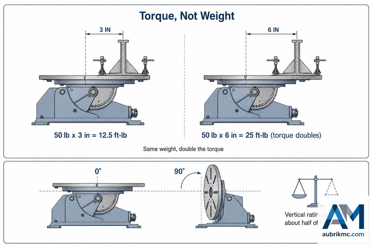
Overloading isn’t a function of how heavy the item on your scale is, but how much torque it places on the drive train. In “Analysis and Design of Positioner Mechanisms for Automatic Welding”, a mechanical engineering thesis conducted at MIT in 2022, researchers detail how the physical stresses placed on a positioner spindle’s bearings are related to a part’s weight as well as its distance from the spindle axis – not its weight alone. According to the study, “The rated motor torque capacity is directly related to the load capacity of the spindle.” Every capacity rating found on a nameplate assumes the part’s center of gravity is at a particular point, and deviating from this point results in different real-world forces on the machine even if the reading on the scale hasn’t changed. Another peer-reviewed article by the International Journal of Engineering Research and Development (IJERD) provides a full, end-to-end example of this mathematical relationship using a small drive: a 60W motor driven at 6,000 RPM with a 1:5 gear reduction that’s designed to handle specific static and dynamic load capacities for a given bearing – precisely the same mechanical principle that drives the torque-bearing load chain, regardless of size.
Trade magazine The Fabricator, an FMA publication, lays out the math with a clear example. Imagine placing a 50 lb. weldment 3 inches away from the positioning table’s surface in the horizontal position; this exerts a torque of 12.5 foot-pounds. Move that same 50 lb. part 6 inches away and you double the torque to 25 foot-pounds, despite using the exact same weight. This principle is why a welding positioner can safely support a specific weight when centered on the table, but can be overloaded with a much lighter but more awkwardly placed workpiece.
Is vertical capacity really half of horizontal capacity?
Vertical de-rating is the most frequent error in machine sizing. If you consider the continuous rotation that a positioner’s table may undergo-ranging typically from 0° to 135° in industrial models-even a static part is constantly being leveraged as the table tilt angle increases, placing increasing overhung load torque on the machine as it moves away from 0°.
Another aspect where capacity isn’t absolute is its dependence on position. Even Koike’s own sizing guidelines say that a positioner is rated for 40,000 lb only when the Center of Gravity (CG) of the load is 12 inches or less from the table surface. Move that CG even an inch or two farther away, and that 40,000 lb rating no longer applies. It’s a common trait among manufacturer capacity charts; Gullco’s GP-200/GPP-200 positioner, rated at 150 lbs at 3 inches from CG, drops to a paltry 37.5 lbs at 12 inches – that’s four times the capacity difference simply from positioning. Always verify both horizontal and vertical ratings before assuming a part “fits.”
6 Warning Signs Your Positioner Is Overloaded
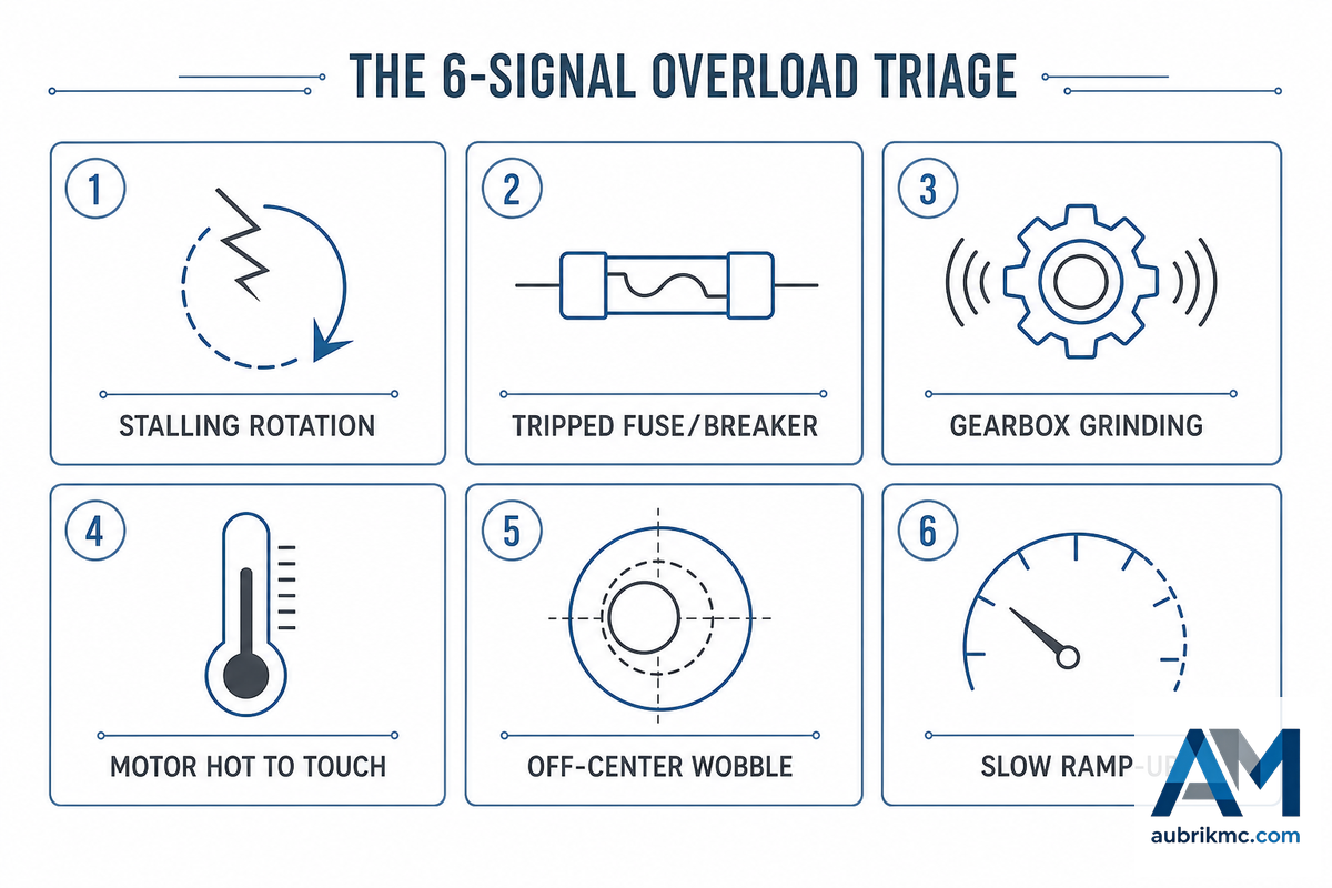
A true overload doesn’t typically kill a machine on the first heavy part; it’s cumulative, and the drivetrain will send clear warning signs well before any critical component fails. Speed changes as the table passes 12 and 6 o’clock are flagged by The Fabricator’s benchtop-positioner guidance as an early, easy-to-catch symptom of an unbalanced or overhung load. The following chart-The 6-Signal Overload Triage-provides a field-friendly check sequence that addresses the lowest cost-to-inspect symptoms first.
| No. | Signal | What It Looks Like | Likely Root Cause |
|---|---|---|---|
| 1 | Stalling or erratic rotation | Table struggles, speeds up or slows down under the same load | Torque demand exceeds motor output |
| 2 | Tripped thermal overload or blown fuse | Control box cuts power mid-cycle; small units often use 1.5–2A fuses | Sustained current draw above rated FLA |
| 3 | Gearbox grinding or whining | New noise under load that wasn’t there on lighter parts | Motor and worm gear fighting excess weight |
| 4 | Motor housing hot to the touch | Noticeably warmer than on a normal shift | Motor pushed past continuous-duty rating |
| 5 | Off-center wobble at 12 and 6 o’clock | Speed visibly changes as an unbalanced load passes top/bottom of rotation | Unbalanced fixture or off-center clamp |
| 6 | Slow ramp-up from a dead stop | Noticeably longer to reach set speed than with lighter parts | Inertial/dynamic load added to static rated weight |
| 7 | No response on startup | Positioner won’t move when commanded | Overload trip already latched from prior cycle |
| 8 | Chuck or fixture grip loosening mid-weld | Part shifts slightly during a long weld pass | Thermal expansion of the part changing chuck grip — check before assuming overload |
| 9 | Burning-plastic smell near the control box | Faint odor, sometimes with a visibly warm power cord | Stray current finding a high-resistance path (see next section) |
The last sign in the list isn’t hypothetical. As one Practical Machinist forum member recounted, after welding stainless fittings on his shop’s rotator for about 20 minutes, he noticed a smell of burning plastic and found that the power cord for the DC speed control was literally melting from the inside, because the welding ground lead had never been attached to the workpiece. Reconnecting the ground to the workpiece immediately resolved the issue, with no damage to the rotator itself. This important distinction-electrical fault versus mechanical overload-is the focus of the next section.
The Hidden Failure Path: How Overload Current Damages Bearings
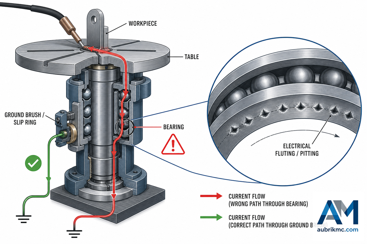
The most common misconception of overload is that it’s simply a “weight” problem. There’s a less apparent and insidious overload path that has absolutely nothing to do with the load’s mass: welding current finding its way through the positioner bearings instead of a proper ground. This phenomenon is cautioned against by three independent equipment manufacturers (Gullco, Westworld, and Baileigh) in their operator manuals. Gullco explicitly states in its technical manual, “A poor welding ground circuit will cause the weld ground to pass through the positioner, causing damage to the motor control, cables, drive system and the main spindle bearings.” Similarly, Westworld’s VP3 manual advises, “If this connection is NOT made the weld current will earth through the centre of the table assembly and damage the bearings and other transmission parts.” Baileigh’s rotator manual corroborates this, adding a specific warning not to ground to the support frame.
This is a phenomenon familiar to anyone who’s done any work with rotating machinery (not just those welding only forums). In Timken’s bearing failure catalog, it’s its own listed category of “Burns From Electric Current”-separate from wear, contamination, or corrosion-with its own visual characteristic: small conical, melted spots arranged in a line around the race in the direction of travel, resembling tiny little bead strings, called electrical fluting or electrical pitting. Here’s how a positioner repairman of 20 years of shop experience describes it in the Miller forum: “small arc strikes on the surface… become much harder than the race or bearing, and as it rolls around it causes damage that then destroys the other parts.” It happens gradually, can’t be seen from outside the positioner, and by the time it start showing up as noise and vibration, the race has usually already been pitted.
What keeps welding current from damaging the bearings?
Proper grounding: providing a properly rated slip ring or spring-loaded brush contact that gives returning welding current an easy low-resistance path back to the welding machine instead of finding it through the bearing. ANSI Z49.1 (Safety in Welding, Cutting and Allied Processes) terminology distinguishes between a work lead and a ground lead-work current should return via a cable appropriately sized for the job, not through some improvised route. Building on that standard, The Fabricator’s grounding guide advises: “the grounding connection must be made independent of the welding-circuit connection and have an adequately rated ground lead,” noting that a rating of “200 amps or more is a good rule of thumb.” Failure to do so (or failure of worn, shop-dust-clogged brushes to make proper contact) forces the welding current to take its own path-often across bearing balls and races. A field study on VFD-driven motors suggests that a normal shaft-to-frame voltage is in the 3 to 5 volt range, but damaging units can exhibit voltages into the double figures and beyond. Consider shaft-voltage measurements with an inexpensive multimeter to be a quick, cheap, early warning-don’t treat the numbers as precise pass/fail benchmarks, though.
📐 Engineering Note
This isn’t a universal or an immediate phenomenon: LinearMotionTips researchers report that the amount of damage is proportional to current magnitude and duration, bearing load, rotational speed, and lubricant quality, and one veteran shop builder noted that he ran heavy weld current through used ball bearings for years with no issue. Treat grounding as a significant risk factor to mitigate, not an automatic doomsday to panic over; the fix (a proper rotary ground) is inexpensive, and the resulting spindle or positioner damage is anything but. And this goes for both manual bays and robotic welding cells: an automated weld positioner still needs its own rated ground-whether the rotation is commanded by a person or a program, the current has no idea which one triggered the arc.
What To Do the Moment You Suspect Overload
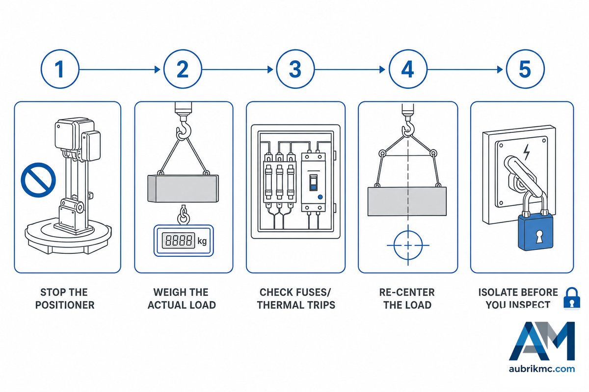
Almost all positioner-drive manufacturers have an almost identical checklist for the first steps to take when the motor trips – and our own documentation from Gullco is pretty much a verbatim match for the typical procedure, often summarized as:
- Stop the positioner. No amount of muscle will get you out of a stall, and repeated trip attempts will strip gears and burn out the motor – it simply can’t endure the repeated high torques involved in a failed move.
- Weigh the actual load. It’s the sum total of the workpiece, plus any fixturing, clamps, chucks, and the payload capacity rating of the drive and its attachments, not just what’s printed on the workpiece label.
- Check fuses and thermal trips. An overload relay trip, as compared to an instantaneous trip caused by a stall, is designed to cool down and reset; repeated trips of a Class 10 overload relay on the same load suggest a genuine overload, not a glitch.
- Re-center the load. A workpiece shifted or mounted off-center, with a fixture and clamps applied, is the most common cause of what seems like overload. Once off-center, the CG is no longer aligned with the axis of rotation, and that causes a binding action and an increase in torque, which trips the overload relay.
- Isolate before you inspect. De-energize and lock out your machine, consistent with OSHA’s machine-guarding requirements, if you’re removing panels to get into the control cabinet, testing for ground with a meter, or approaching the chuck and fixture with a tool. Rotational energy and gravitational pull (if the load isn’t perfectly horizontal) are still factors, even after the drive has tripped.
One caution noted across several manuals: don’t reverse rotation before the machine has stopped moving, and don’t initiate start-stop-start sequences repetitively without waiting for the motion to cease. These actions increase rotational inertia loads above what may be present under static load conditions and are cited in warnings as potential overload triggers.
Overload vs. Normal Wear vs. Other Faults
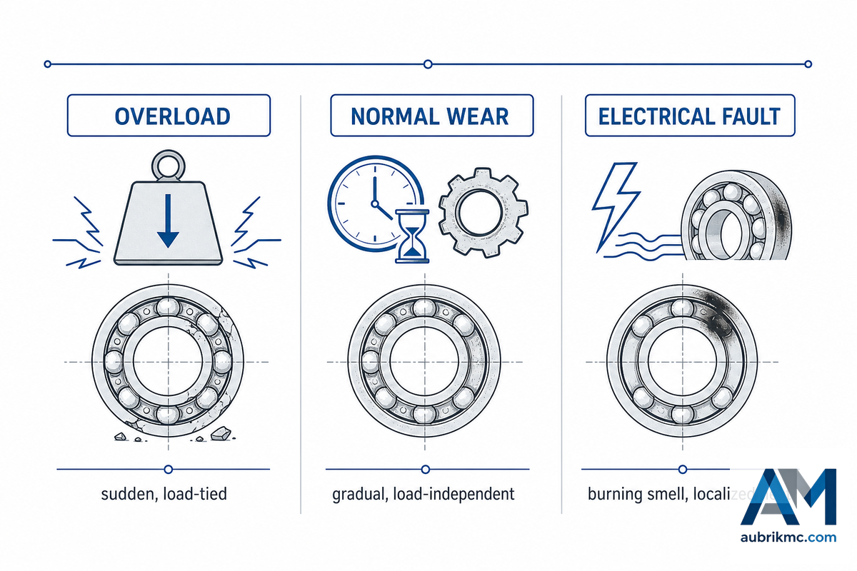
Not all roughly-running positioners are over-loaded. A field investigation by the UK Health and Safety Executive reported that many positioners in use had been modified and/or refitted and were of very advanced age. As a result, many units aren’t operating at original specifications and their nameplate rating may not represent the machine’s true capabilities. Don’t diagnose overload until you’ve ruled out other factors.
| Symptom | If Overload | If Normal Wear | If Electrical/Grounding |
|---|---|---|---|
| Rotation speed | Stalls or surges only under the heavy part | Slow, consistent drift regardless of load | Usually unaffected |
| Noise | Grinding tied to load weight/position | Constant low-level noise on every job | Usually silent until failure |
| Heat | Motor housing hot under heavy loads specifically | Gradual, load-independent warmth | Localized heat at ground point/cable |
| Smell | None typically | None typically | Burning plastic/insulation near control box or cabling |
| Onset | Sudden, tied to a specific heavy/awkward part | Gradual over months/years of service | Can be sudden (loose lead) or slow (degraded brush) |
| Fuse/breaker behavior | Trips reproducibly on the same load | Rarely trips | May trip erratically or not at all |
| Chuck/clamp grip | Can slip if fixture wasn’t rated for the load | Loosens slowly with age | Usually unaffected |
| Vibration | Correlates with an unbalanced/off-center load | Increases slowly as bearings age | Not a typical symptom |
| Best first check | Re-weigh the load + fixture, check CG offset | Service log — when was it last inspected? | Continuity-check the ground path with a meter |
| Who confirms it | Load calc against rated + CG chart | Borescope/vibration analysis of bearing races | Shaft-to-frame voltage reading (elevated vs. baseline) |
One data point underlying the last statement: the study cited above put normal shaft-to-frame voltage at 3V to 5V, with motors actually suffering this kind of damage reading well into double digits and occasionally far higher in lab tests. When these readings come up noticeably high, the problem is likely electrical rather than mechanical. Any excess workpiece load is irrelevant to such damage, as are modifications that affect it; and either type of problem will result in the kind of damage that can be detected in the weld before it is seen on a failed component or overload trip. (Erratic travel speed, after all, disrupts the controlled movement that’s the entire purpose of a positioner, just as erratic speed variation across the rotation range creates inconsistent weld beads.)
Preventing Repeat Overloads
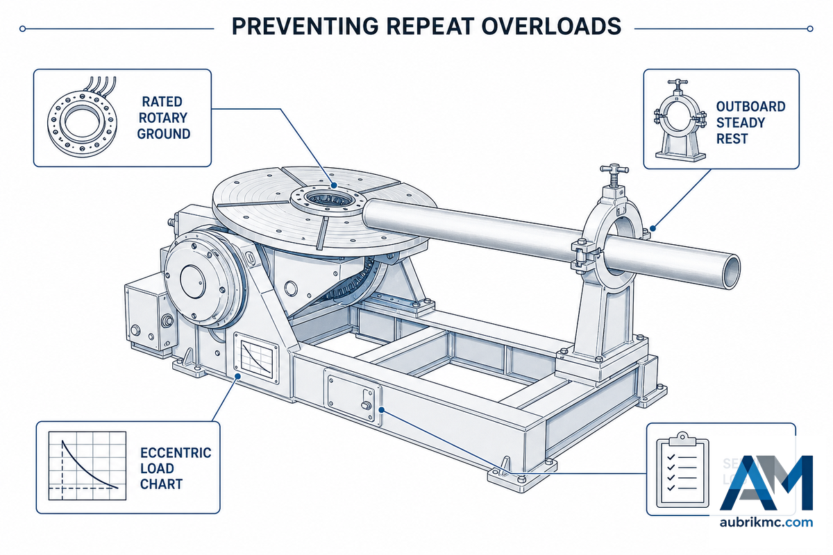
✔ Do
- Size to the eccentric/CG-adjusted chart, not the headline rating
- Apply a rated rotary ground (slip-ring or brush type) with an amp capacity equal to your weld current; use the 125%-of-rated-current guide line for motor-protection fusing if no manufacturer’s data is available.
- Provide outboard supports, steady rests, or similar fixtures to handle long, tall, overhanging, or unbalanced workpieces.
- Slow the rotation speed on heavy or overhung loads to minimize rotational shock load; a 0.03 to 30-rpm drive is broad enough to achieve significant speed reduction without stalling the motor.
- Keep a service log – repeating visits to the same job within 30 days indicate a sizing issue, not an anomaly.
⚠ Don’t
- Assume the horizontal rating will be valid after the table has been tilted.
- Ground the welding lead to the frame of the machine, not the part being welded.
- Reset an overloaded, tripped circuit repeatedly without addressing the reason for the trip.
- Reverse rotation direction before the table has fully stopped
- Run a positioner at 100% of rated capacity as standard operating procedure.
That last one is worth spending a minute or two on. “if a fabricator has a 10,000-lb. part, it needs a 10,000-lb.-rated positioner. But that’s a short-sighted decision, because a positioner loaded to its maximum capacity 100 percent of the time will have a reduced lifespan.” as Don Burgart, Welding Product Manager at Koike Aronson/Ransome, so aptly stated in the recent Fabricator article: “proper sizing with a margin for future application development is a simple and relatively inexpensive precaution against a host of potentially much more costly future problems. In many cases it represents the least expensive path to overall operational reliability and success.”
None of this logic will change no matter which welding system you connect to the positioner. Regardless if it’s a production welding cell running continuous welding with a rotary positioner, a small shop that uses a tabletop unit to precisely position small brackets for electric welding, or a high-production pressure vessel manufacturer that requires a headstock tailstock positioner for complex welding operations on vessel shells, the mathematics of center of gravity (CG) and torque will be the same – it will only change the magnitude of the numbers. Technical specifications (rated load, RPM range, tilt range) are found on the nameplate. What the machine can actually do with your particular workpieces during welding is found in the eccentric load chart. Consulting both the nameplate and the eccentric load chart on each new job – not just the first time you weld that part – is the critical step to ensure the speed of rotation and degree of tilt are properly synchronized with the part load to prevent it from showing up on your service log as a tripped overload.
“a positioner loaded to its maximum capacity 100 percent of the time will have a reduced lifespan.”
Don Burgart, Welding Product Manager, Koike Aronson/Ransome, via The Fabricator
Repair or Upsize? The Decision Point
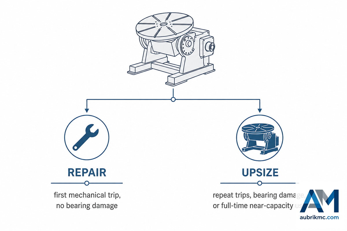
Most shops sooner or later have this question come up when the same positioner has to be repaired after being tripped a second or third time on the same project: “Is it worth fixing this again or should I buy a positioner with a higher load capacity?” There are no official industry guidelines that will help you make that decision – only you know whether the cost of repair outweighs the cost of being down. For the decision-making factors that will help you determine if it’s time to repair or replace, see The Repair-or-Upsize Threshold below.
Repair vs. Upsize: Key Factors to Weigh
- Is it an isolated case or is it becoming routine? An occasional oversized job may warrant an out-of-line support or running a lower speed, but a consistently higher load suggests it’s a size issue.
- What’s the repair cost compared to a used replacement? For an older industrial drive system (generic for manipulators but useful for estimation on positioners), a control box alone commonly runs $3,000–$8,000, and a full AC drive-and-motor swap runs $5,000–$12,000, and a full retrofit could “reach or exceed the cost of a comparable late-model used” unit, according to manufacturers, so it makes sense to shop around.
- Has this unit already experienced bearing or grounding damage? If the machine has already suffered electrical pitting, it’s a poorer candidate for repair than a unit that suffered its first mechanical overload trip.
- What’s the cost of being idle? Having an entire welding cell tied up because of a positioner issue is a far more serious financial problem than having a stand-alone tabletop unit down for a repair, especially if you’ve a spare ready to go.
- Did the fix go outside original ratings? ANSI Z49.1 makes clear a modification may not push the electrical or mechanical rating beyond what the machine was originally built for; a fix that quietly raises capacity or reroutes current isn’t a repair anymore – it’s an unrated modification, and it belongs with the machine builder or a certified technician.
Broader market analysis of the capital-equipment sector confirms the same retrofit-or-replace logic: rotator and positioner fleets can gain efficiency from retrofits without buying new equipment, provided the base frame and bearings are still sound. But the repair economics change considerably once the original frame or bearing already has electrical damage.
Should the repair-vs-upsize math be favouring a new unit, size it for the class of part rather than the failure itself – read through our guidance on rotary welding positioners, pipe welding positioners, welding turntables, and heavy-duty welding positioners on the best way to size for your specific class of workpiece. All models within the Aubrik welding positioner range specify capacity both in the horizontal and in eccentric/CG-offset orientation, and rather than give you the headline figure only, all their eccentric load data is published as a full chart – use the load capacity calculator to check a specific part against a given model before you order.
None of this is tied to one welding system or one welding method. A one-man shop doing manual welding and using welding positioners on occasional welding jobs runs the same overload equation as a production line running arc welding, TIG welding, MIG welding, or stick welding on an hourly basis; an automated robotic cell running positioners in robotic welding operations just reaches the failure curve faster, because there’s no welder standing there to notice the warning signs before they go critical. It makes no difference what type of welding work you’re doing or what welding applications and welding equipment you run — table top welding positioners and the largest types of positioners in the shop, including a headstock tailstock positioner or a rotary table, all answer to the same welding process physics. Every operator’s goal is the same: high-quality welds, weld quality and consistency job after job, and a well thought out process for choosing a welding positioner and getting the rotation speed and angle right before the arc ever strikes.
Size the weld positioner correctly and do your grounding work properly once, and a well-designed positioner should deliver consistent welding results and years of service without a premature overload.
Every shop’s welding needs are different, but the economics aren’t: fixing the risk up front protects both weld time and the quality of your welding operations far more cheaply than troubleshooting a blown-out motor or an acid-pitted spindle bearing after the fact, whether the motor powers a full-automation cell or precision welding done by hand. There’s no version of “optimal welding” or overload protection that starts with equipment already running out of specification, and no way to increase productivity that survives an unplanned rebuild. Get the fundamentals — inspection, grounding, sizing — right across every set of weld joints and welding tasks on the schedule; that’s what lets you improve weld quality instead of just chasing troubleshooting tickets.
Why We Write This
In spite of a mountain of positioner content on the Web (mostly for-sale pages for new units and “borrowed” maintenance check lists on obscure industrial sites), there’s very little out there that helps anyone diagnose the real cause of a problem on a working machine. This article fills in some of those blanks by integrating the electric motor bearing-damaging sequence into the machine, based on data from three major manufacturers’ OEM manuals and the bearing-industry standard, because this particular overload mode is almost unknown in the industry but probably ruins more positioners than any other.
Frequently Asked Questions
Q: What is the difference between a welding positioner and a welding fixture?
Positioners are powered machines that rotate and tilt the workpiece under motor control; fixtures, by contrast, are passive holding devices with no motion of their own.
The “positioner” carries loads with geared motor-drive motion, usually to bring a part into flat, downhand weld position. The “fixture” carries the part but adds no mechanical movement of its own; fixtures may include such devices as clamps, jigs, or simply the surface of a welding table. They often are mounted onto positioner tables and may share their loads with the positioner, but they contribute no torques and only minimal to the mechanical and electrical capacities of the machine.
Q: Can a one-time overload permanently damage a positioner, or does it recover?
Most single overload events are recoverable if caught quickly; damage becomes permanent when the same overload repeats or when it went unnoticed for a while.
The good news is that the same overloads which might destroy the machine’s components may be quickly corrected with only limited or no damage. If you are successful in arresting the overload and it does not occur again in service for many hours or months, it is possible that the load condition will not permanently damage any part. However, there are two scenarios in which overloads do lead to lasting damage: The first occurs when overload is repeated for any prolonged period; any overload condition to any component will impose some “fatigue” on that part and a repeat overload on a specific component can be enough to produce its failure or degradation; the second involves repeated overload which is not stopped, with no load protection available or functional in the motor-driven positioner, leading to gradually progressive and ultimately destructive changes to all major mechanical components, as well as potentially “cooked” motors or bearings. Because the OEM considers each instance a sign to thoroughly analyze its underlying cause, they view any recurrent trip to be of much more significance than a one-off occurrence.
Q: Is a grinding or whining gearbox always an overload symptom?
No, not always — grinding and whining can also come from dry lubrication, worn gear teeth, or debris in the drive path, independent of any load issue at all.
No. Other common causes for grinding and whining sounds may exist in any motor drive train, including: •Insufficient lubrication of bearings, gears, or the chain; •Loosely adjusted gear backlash; or •Foreign debris present in the drive path. Whether the noise becomes audible or is more significant only when you apply specific load may therefore be used as a diagnostic method. A grind or whine present on all jobs is unlikely to be related to load but instead points toward ordinary wear that you should expect to observe through a history maintained on your equipment through regular scheduled inspections.
Q: What amperage fuse should trip before the motor is damaged?
Fuse rating depends on motor size, but small benchtop units commonly use 1.5A to 2A fuses; always match your specific model’s own nameplate rather than a generic industry rule.
Small, benchtop positioners typically run 1.5A to 2A fuses — published OEM examples range from a 1.5A fuse on a 1/15 hp drive up to 2A on slightly larger 100 lb to 200 lb units. Industry practice dictates using a fuse that’s 125% of the full-load amperage, and always use the figure on your machine’s nameplate, not some generic figure.
Q: Does tilting the table really change how much weight it can safely hold?
Tilting the table really does change the safe capacity — it converts flat weight into overhung torque, which is why vertical ratings on a given machine run well below its horizontal rating.
Yes. When the table is flat, the weight of the part is carried directly down through the spindle; tilt it up toward the vertical axis and that same weight now extends outward away from the axis, imposing torque the flat setup didn’t have. That’s the same basic principle behind CG-distance derating in the guide section mentioned previously; the only difference is it’s through an angle rather than distance on a flat plane. It’s why manufacturers routinely publish both horizontal and vertical load capacities in their specification sheets instead of a single number.
Q: Can outboard support fix an overload problem instead of buying a bigger positioner?
Outboard support often fixes it for long or tall workpieces specifically — a steady rest or roller stand reduces the overhung load the positioner itself has to carry.
Yes, most often, if the part is long or tall; a roller support or a steady rest supports it, taking the overhung load off the bearings. A roller won’t help if the part is truly overloaded for the base capacity, and if the fuse continues to blow even with a roller, that’s an indication of a true capacity problem (see repair or upsize section, above), rather than a geometric issue.
References & Sources
- MIT Mechanical Engineering Thesis, Positioner Spindle Design — MIT DSpace
- 29 CFR 1910.212, General Requirements for Machine Guarding — OSHA
- OC 668/26, Positioning Equipment Field Investigation — UK Health and Safety Executive
- Welcome to the World of Positioneering — The Fabricator
- Staying Grounded — The Fabricator
- Putting the Spin on Benchtop Positioners for Tube and Pipe Welding — The Fabricator
- Bearing Damage Analysis Reference — Timken
Related Articles
- How to Use a Welding Positioner — setup, grounding, and rotation speed basics
- Welding Positions Explained (1G–6G) — why positioners exist in the first place
- How to Choose a Rotary Welding Positioner
- Heavy Duty Welding Positioner Selection
- Welding Positioner Load Capacity Calculator