Get in Touch with Aubrik Company
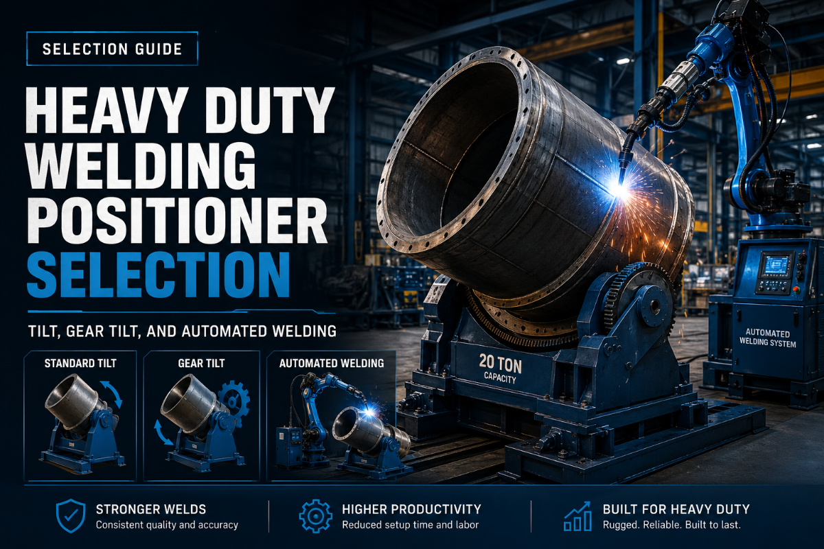
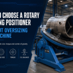
Heavy Duty Welding positioner choosing is done even in the event when a customer has not yet requested for costs. The rated load is not the only thing of concern, so is the center of gravity, the weight of the fixture, the height of the table, the tilt spectrum, control of the rotation at low speed, and the manner in which the workpiece is to be held together in the weld.
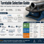
Quick Specs: Buyer Inputs to Prepare
| Load data | Workpiece weight, fixture weight, center of gravity, and expected future load class |
| Motion data | Required tilt angle, 360-degree rotation need, work height, and controlled low-speed RPM range |
| Holding method | 3-jaw chuck, T-slot table, pipe flange fixture, custom tooling, or robot cell fixture |
| Acceptance checks | Guarding, ventilation, grounding, speed stability, emergency stop, and documented welding quality controls |
Why This Guide Supports the Heavy-Duty Welding Positioner Product Page
This is a selection worksheet, not a secondary product listing. It is intended to support a fabrication, pressure vessel, wind tower, shipbuilding, and heavy equipment buyer in clearly specifying workpiece and weld position to the salesperson prior to discussions regarding models, lead time and quotations.
Product pages answer “which model can I buy?” This support article answers “what data should I prepare so the selected weld positioner is not undersized, awkward to fixture, or hard to accept after delivery?” That split matters because the visible search results for this query are mostly commercial; the article prepares the buyer, then sends the buying conversation to the correct product page.
Load Capacity Comes First: Weight, Payload, and Center of Gravity
Rated load is the starting point, not the whole selection. A heavy weld positioner has to carry the workpiece, the fixture, and the changing moment created when that mass tilts or rotates away from the centerline. If the fixture pushes the center of gravity outward, two machines with the same nameplate load can behave very differently.
Before asking for a model, separate four figures: workpiece weight, fixture weight, distance from the table face to the center of gravity, and distance from the rotation centerline to the center of gravity. Without those inputs, the supplier has to guess. That is where heavy-duty projects lose time, especially when a 3-ton frame or pipe flange assembly is treated like a balanced flat plate.
Engineering Note
Ask for both weight capacity and moment-load review. A workpiece can weigh less than the stated payload and still overload a tilt or rotation drive if its center of gravity sits far from the table face. Confirm reserve against the supplier’s load chart instead of judging from workpiece weight alone.
- Total payload = workpiece plus fixture, chuck, temporary brackets, and any counterweight.
- Offset of the centerline has a bigger impact on the drive train than most people would have guessed.
- Future work should be considered if the shop is moving toward larger pressure vessel, wind tower, or machinery weldments.
Tilt Range, Table Height, and 360-Degree Rotation
Positioners earn their place when they move the weld into a better working position without unsafe rigging. Tilt range decides whether the joint can be presented at a practical angle. Table height affects whether the operator works near a comfortable reach zone or stretches into fatigue. Rotation helps long seams, round weldments, and pipe flanges move under control instead of going back to the crane again and again.
For a large weldment, the better question is not simply “Does it tilt?” Ask, “Can it reach the weld angle my sequence requires while the workpiece and fixture stay inside the approved load chart?” That wording forces the supplier to consider tilt, center of gravity, and fixture geometry together.
| Buyer question | Why it matters | RFQ input |
|---|---|---|
| Do I need forward tilt? | Access to a root pass or flange face may depend on work angle. | Target angle range and weld sequence. |
| Do I need full rotation? | Round assemblies may need continuous access around the joint. | Diameter, seam length, and required rotation mode. |
| Is fixed height enough? | Height affects posture, torch access, and fixture loading. | Desired table height or height adjustment need. |
How does a welding positioner work?
In practice, the welding positioner holds the workpiece on a table, chuck, or fixture, then rotates or tilts it so the welder or automation system can reach the joint from a more stable position. The main machine functions are holding, rotation, tilt, and controlled speed. Engineering review starts by checking that those motions are safe under the real payload and center-of-gravity condition.
RPM, Rotary Welding, and Welding Process Control
Rotation speed is not one-size-fits-all. A small pipe, a large flange, and a wide tank shell may show similar table RPM while needing very different surface speed. That is why buyers should ask whether the drive can hold steady low-speed rotation under the actual workpiece load, not only whether the motor has a high top speed.
For TIG, MIG, submerged arc, or automatic welding, the movement has to match the process. The operator may need a slow continuous turn, indexed rotation, or manual jog control. Weld quality still depends on fit-up, joint preparation, shielding, current, travel speed, and access; positioning helps only when it gives the welder a stable reference.
Buyer Check
Ask for the usable low-speed range under load, not only the motor rating. Shop-floor discussions around weld positioner RPM often point to the same lesson: smooth, slow rotation for the workpiece diameter and welding process matters more than top speed.
Can I use a welding positioner with MIG, Stick, and TIG welding?
Often yes, but the fit depends on grounding, fixture design, speed control, table access, and heat input. TIG work may care most about smooth low-speed movement and torch angle. MIG or submerged arc work may care more about duty cycle, grounding, spatter exposure, and fixture repeatability. Give the supplier the process, current range, workpiece drawing, and weld sequence before choosing the machine.
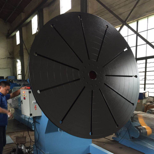
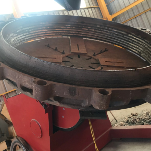
Chuck, Fixture, and Workpiece Geometry
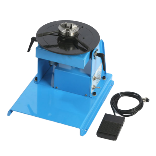
Use a 3-jaw chuck when the workpiece is round and can be gripped safely. Pipe flanges, rings, and smaller tubular parts are common examples. Heavy plate weldments, tank heads, frames, and off-center assemblies may need a T-slot table, custom fixture, locating pins, or a welded fixture plate instead.
Bad fixturing can make a high-quality positioner feel weak. If the workpiece is not seated flat, if clamp points distort the part, or if the fixture adds too much offset, the machine may see a larger moment load than the buyer expected. In heavy fabrication, fixture design belongs in the equipment discussion, not as a shop-floor afterthought.
| Workpiece geometry | Likely holding method | Question to ask |
|---|---|---|
| Pipe or flange | 3-jaw chuck or pipe fixture | What clamping range and jaw style fit the part? |
| Box frame or bracket weldment | T-slot table with fixture plate | Where is the center of gravity after fixturing? |
| Tank head or shell section | Custom support, rotator, or manipulator pairing | Is a positioner or turning roll the safer primary tool? |
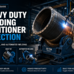
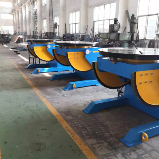
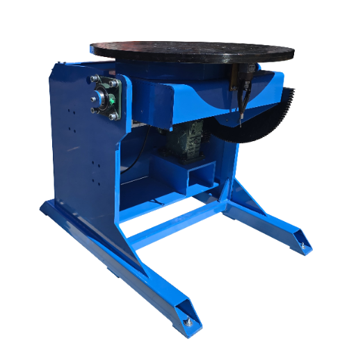
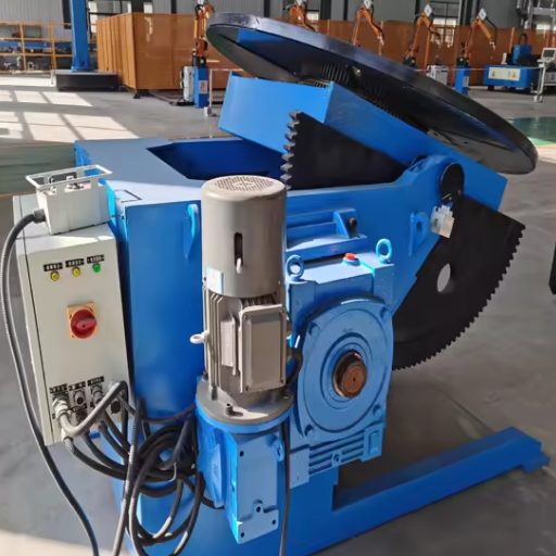
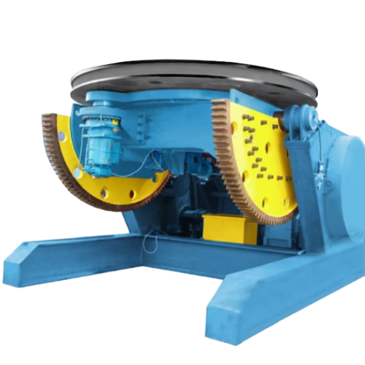
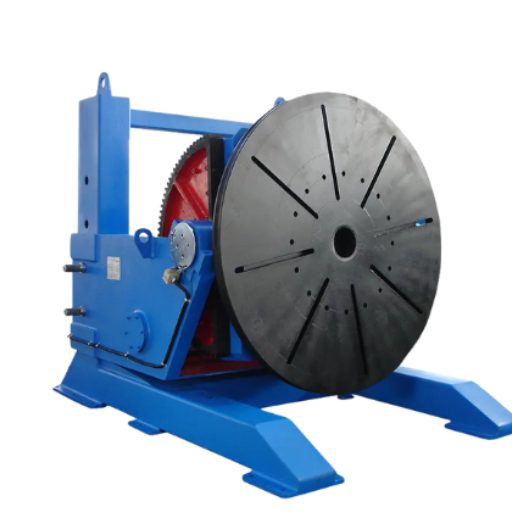
Benchtop, Gear-Tilt, Turntable, Rotator, and Compact Positioners: Which Type Fits?
Not every weld positioner is a heavy-duty machine, and not every heavy-duty machine is the right fit. Benchtop positioners suit small parts and light fixtures. Floor-mounted turntables suit heavier round assemblies. Gear-tilt positioners handle tilt and rotation together. Rotators carry cylindrical work such as pipe or vessel sections, while manipulators move the torch or welding head rather than the workpiece.
Selection should follow the workpiece shape first, then load, then process. A long cylinder may be better served by a rotator. A compact but heavy part may call for a tilt-rotate positioner. If the part must align with an automatic welding head, the manipulator and positioner may need to work as a pair.
What are the different types of welding positioners?
Common categories include floor-mounted turntables, benchtop positioners, head-and-tailstock systems, manipulator welding systems, pipe rotators, and tilt-rotate positioners. Market names overlap, so describe the motion you need: rotate a round part, tilt a heavy weldment, hold a pipe flange, or coordinate with an automatic welding head.
Advantages and Limits
Tilt-rotate positioner
Works best when a compact heavy workpiece needs controlled tilt and rotation at the table. Check center of gravity and fixture offset.
Welding rotator
Ideal for long cylindrical pieces requiring support along the entire length, though it may not accommodate fixture designs for a non-round weldment.
Productivity Notes for Rotary Welding Positioners and Material Handling
Buyer vocabulary can be inconsistent, so it helps to translate common catalog wording into shop decisions. Catalogs may call the rotating table a welding positioner turntable, which usually means a positioner table built to rotate a part in place. Rotary welding positioners are discussed when the weld path benefits from steady rotation, especially on round parts, pipe spools, and pipeline fabrication fixtures.
Do not treat productivity as a promise made by the machine alone. Every high-quality weld still depends on joint preparation, welding current, fit-up, shielding, and inspection. The right motion can improve weld quality by making the joint easier to reach, but the fixture and welding process must still fit the part.
For industrial welding projects, compare each positioner series by table diameter, fixed height, drop center options, rotation and tilting capabilities, and whether the table can rotate 360 degrees. Some tilt tables quote a 135° tilt angle, while other designs are built for easy positioning from overhead or vertical work into a flatter range. Smaller weldments may suit compact positioners; large and heavy assemblies usually need a more conservative load review.
Precise control and operator comfort belong in the same conversation as material handling. If the shop wants to increase efficiency without adding risk, the RFQ should describe the welding tasks, fixture method, and how the workpiece moves from crane, roller, or manipulator into the weld station.
Moment-Load Ladder for Heavy-Duty Positioner Selection
Use a Moment-Load Ladder to sort the quote request conversations instead of using a request form asking for a heavy-duty positioner. Go from part data to motion data. Suppliers can use these inputs to dimension the positioner, drive, table, fixture, and control.
| Step | Input | Decision it drives |
|---|---|---|
| 1 | Workpiece weight | Base payload class |
| 2 | Fixture and chuck weight | True supported mass |
| 3 | Center of gravity from table face | Tilt load review |
| 4 | Offset from rotation centerline | Rotation torque review |
| 5 | Required tilt range | Gear tilt and frame selection |
| 6 | Required low-speed rotation | Drive and control selection |
| 7 | Weld process and current range | Grounding and duty review |
| 8 | Shop safety requirements | Guarding, emergency stop, and access checks |
| 9 | Future part family | Whether to size for one job or a repeat production cell |
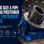
RFQ Details to Send Before Requesting a Heavy-Duty Positioner Quote
Useful RFQs are short but specific. Tell the supplier what the positioner must hold, how the weld will be made, how the workpiece is gripped, and whether the station will stand alone or connect to a larger welding system.
Established in 1999 as Wuxi ABK Machinery, Aubrik specializes in welding equipment, CNC cutting machines, wind tower production lines, H-beam welding lines, pipe welding equipment, grinding machines, roll forming machines, and plate bending machines. The company reports annual capacity of 1,000 sets of welding equipment and 200 sets of cutting equipment, with ISO9001 and CE certified products, OEM service, and a one-year free warranty.
The sample values below are not Aubrik model ratings. They show the format a buyer can use when sending drawing data for supplier review. Replace every number with the real workpiece, fixture, power, and shop acceptance data before asking for a quote.
| RFQ field | Example placeholder | Why the supplier asks |
|---|---|---|
| Workpiece mass | 3,000 kg | Defines the base payload check. |
| Fixture and chuck mass | 500 kg | Prevents undersizing from hidden tooling weight. |
| Total supported mass | 3,500 kg | Keeps the load chart review tied to the full setup. |
| Center of gravity from table face | 450 mm | Shows the tilt moment created by the part. |
| Offset from rotation centerline | 300 mm | Shows the rotation torque condition. |
| Part envelope | 1,200 mm diameter; 900 mm working height | Checks table access, reach, and guarding space. |
| Fixture plate envelope | 1,500 mm by 1,500 mm | Checks table size and bolt pattern fit. |
| Welding current range | 250 A to 600 A | Supports grounding, cable, and duty review. |
| Factory power | 380 V, 50 Hz | Aligns motor and control package planning. |
| Control circuit preference | 24 V or 48 V | Helps the supplier match plant control practice. |
| Load reserve request | 20% reserve | Gives engineering room for fixture variation. |
| Speed stability acceptance | within 5% during trial weld | Turns “smooth rotation” into a checkable request. |
| Guard clearance target | 200 mm service access | Keeps maintenance and pinch-point review visible. |
| Grounding lead review | 600 A shop maximum | Keeps welding current and grounding path in the same review. |
| Pendant cable reach | 5 m operator reach | Checks whether the control point fits the loading area. |
| Future fixture allowance | 200 kg extra tooling | Allows for repeat jobs that need a heavier fixture plate. |
| Control cabinet allowance | 1.5 kW auxiliary load | Flags added control hardware before the layout is fixed. |
| Shift duty example | 8 hours per shift | Frames expected use without claiming a fixed duty cycle. |
- Part drawing or photo with main dimensions.
- Maximum workpiece and fixture weight.
- Center of gravity estimate or fixture layout.
- Required tilt range, table height, and rotation mode.
- Processes offered: Automatic welding, robotic welding, submerged arc, TIG, and MIG/MAG.
- Factory power, control preference, guarding needs, and delivery market.
Once those inputs are ready, buyers can review Aubrik’s heavy-duty welding positioner specifications and send the part data for a project-specific recommendation.
Acceptance, Guarding, and Operator Safety Checks
Safety review should treat the positioner as rotating industrial machinery, not merely a welding accessory. OSHA 1910.212 covers machine hazards such as point of operation, ingoing nip points, rotating parts, flying chips, and sparks. That wording matters when a table, chuck, or fixture rotates near an operator.
Welding hazards are not only mechanical. OSHA 1926.353 describes ventilation for welding, cutting, and heating, including local exhaust hoods arranged close to the work so fumes and smoke are removed at the source. If a positioner changes where the weld is made, the fume-control plan may need to move with it.
Quality controls should also be documented. ISO 3834-1:2021 sets the framework for selecting quality requirement levels for fusion welding of metallic materials and applies to manufacturing in workshops and field installation sites. For structural steel work, the AWS D1.1/D1.1M:2025 structural welding code page is a useful pointer when buyers need code context with their welding engineer.
Acceptance Checklist
- Confirm payload, fixture, and center-of-gravity assumptions against the supplier’s approved load chart.
- Check emergency stop, pendant control, grounding path, and controlled movement before production welding.
- Review guarding around rotating parts, pinch points and table edge.
- Check ventilation and fume extraction before starting or after rotating the part.
- Record acceptance observations in the shop’s welding quality file.
What Is Changing: Automated Welding, Robotic Cells, and Positioning Equipment
Heavy-duty positioning equipment is increasingly discussed as part of a welding cell rather than a standalone table. Buyers may start with manual welding, then later add automatic welding, robotic welding, or a manipulator. The practical planning question is not “Will this positioner work with robots someday?” It is “What signals, grounding, fixture repeatability, and access envelope would a future cell require?”
Ergonomics also belongs in the decision. CCOHS lists awkward body postures, static positioning, and continuous force as welding risk factors, and recommends positioning the welding item as flat as possible between waist and elbow height when practical. A positioner cannot replace training, guarding, or ventilation, but it can help put the work in a better zone when the workpiece and fixture are sized correctly.
Do not claim a numeric automation trend without a credible source for this exact equipment class. Use a practical planning rule instead: if the shop expects repeat work, documented part families, or future robotic welding, define automation readiness in the RFQ now. That may include pendant control, repeatable fixture points, stable low-speed rotation, interface requirements, and spare capacity for the next workpiece family.
Related Aubrik Resources
Use these pages to keep selection research, product review, and adjacent equipment choices separate before sending an RFQ.
- Heavy-duty welding positioner product specifications
- Aubrik welding positioners category
- Rotary welding positioner guide
- Welding turntable selection guide
- Pipe welding positioner guide
- Welding positioners and turntables comparison
- Pipe rotator for welding guide
- Welding rotators and turning rolls guide
About This Selection Guide
This guide focuses on pre-RFQ selection work for heavy-duty weld positioner buyers. It uses Aubrik’s supplied company facts, public safety and welding-quality sources, and buyer-side decision logic. Exact model sizing should always be confirmed from the workpiece drawing, fixture plan, and supplier load chart.
FAQ
Q: What is a heavy-duty welding positioner used for?
View Answer
It holds, rotates, or tilts large workpieces so the weld joint can be reached from a safer and more stable position. Common uses include heavy machinery, pressure vessels, pipe and flange work, wind tower fabrication, shipbuilding, and structural welding. In many shops, the practical gain is fewer crane resets and a joint angle the welder can repeat.
Q: How do I calculate welding positioner load capacity?
View Answer
Begin with workpiece weight, then add fixture weight, chuck weight, temporary supports, and any offset caused by the center of gravity. Send those values to the supplier so tilt load and rotation load can be checked against the approved load chart.
Q: What is the difference between a welding positioner and a welding rotator?
View Answer
Positioners hold the workpiece on a table, chuck, or fixture and may tilt and rotate it. Rotators support cylindrical work, such as pipe or vessel sections, on powered or idler rolls. Some production lines use both tools when the part family needs round-part support and fixed-table positioning.
Q: Do I need a 3-jaw chuck for pipe or flange welding?
View Answer
Use a 3-jaw chuck for round parts that can be gripped securely and released without distortion. It is common for pipe flanges, rings, and short cylindrical parts. Larger, off-center, or irregular weldments may need a T-slot table, fixture plate, locating pins, or custom clamps so the real load path is carried through the fixture.
Q: What RPM range should a welding positioner have?
View Answer
No one RPM fits all needs. The choice of speeds depends upon diameter, type of welding, traverse speed and the bead profile desired.
Q: Can a welding positioner be used with robotic welding?
View Answer
Yes, if the positioner, fixture, controller, grounding, access envelope, and robot cell interface are designed for that use. Buyers planning a future robotic cell should say so during the RFQ stage so spare capacity, signal access, and fixture repeatability are discussed before the equipment is built.
Q: What should I check before accepting a heavy-duty positioner?
View Answer
Check load assumptions, fixture security, center-of-gravity data, emergency stop, grounding, controlled movement, guarding, ventilation position, and the shop’s welding quality file.
References & Sources
- OSHA 1910.212: General requirements for all machines
- OSHA 1926.353: Ventilation and protection in welding, cutting, and heating
- OSHA 1910 Subpart Q: Welding, Cutting and Brazing
- ISO 3834-1:2021 quality requirements for fusion welding
- AWS D1.1/D1.1M:2025 Structural Welding Code – Steel
- CCOHS welding ergonomics guidance