Get in Touch with Aubrik Company

Tube to Tube Welding Machine Guide: Process, Fit, and Buyer Checks


Buyer guide for boiler, heat-exchanger, and industrial tube fabrication teams
A Tube to Tube Welding Machine is equipment used to join two tube ends or tube sections with controlled weld head motion, current, shielding, and fixture support. Buyers usually don’t need another product page first. They need to understand what a welding system controls, where a weld head can fail the joint, how orbital GTAW differs from resistance subtypes, and what proof a supplier should present before a purchase order proceeds.
This guide is intended as the research layer before selecting a machine. When you already understand the tube diameter, wall thickness, material, access limits, and acceptance route, review Aubrik’s tube to tube welding machine solution for machine-specific configuration details. When those inputs are still unknown, start here.
Quick Specs to Gather Before Any Quote

| Input | Why it matters | Buyer note |
|---|---|---|
| Tube outside diameter | Sets clamp, weld head, and clearance choice. | Record OD in mm and allowable ovality. |
| Wall thickness | Changes heat input, penetration risk, and support needs. | List nominal and minimum wall. |
| Material | Affects GTAW current, electrode setup, shielding gas, and purge. | State carbon steel, stainless steel, alloy, titanium, or nickel alloy. |
| Access around joint | Decides whether the orbital weld head can rotate and clamp. | Send photos or drawings. |
| Evidence route | Defines sample welds, procedure scope, NDE, leak test, or visual check. | Confirm project code before buying. |
This checklist reduces a common specification risk because a 315 A or 350 A power source cannot compensate for the wrong fixture, tube OD, or inspection route. In a production application, send Aubrik the 15-170 mm range target, wall data in mm, material grade, and sample-weld requirement so the factory discussion starts with evidence rather than a catalog label. Aubrik’s ISO 9001 and CE supplier context is useful, but the decisive proof is still the project-specific weld sample.
Key takeaways: Treat machine current as one input, not the decision. Safer shortlists compare weld head fit, power source control, tube support, purge/shielding, maintenance evidence, and the governing inspection route. No machine brochure alone settles code acceptance.
What a Tube to Tube Welding Machine Actually Controls
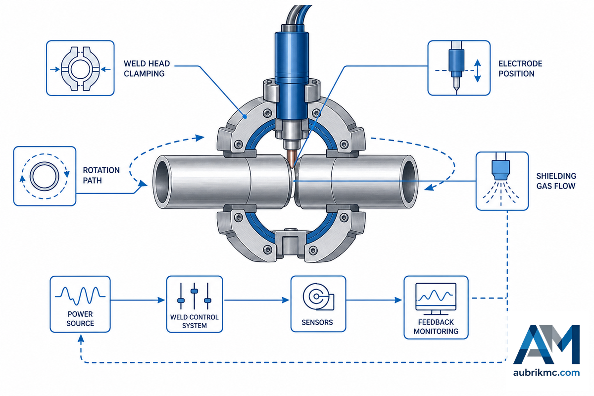
A tube to tube welding machine controls the repeatable aspects of the weld: weld head motion, arc path, welding current, arc voltage, tube position, shielding gas, purge timing, and tube holding method. In orbital weld work, the weld head traverses a fixed pipe or tube; in resistance subtypes, force, electrode contact, timing, and electrical safety controls become part of the purchase question.
In terms of process, GTAW means gas tungsten arc welding. A complete orbital welding system includes the orbital weld head, welding power supply, welding electrode, inert gas shielding, program memory, and fixture support. Buyers may also see related language such as TIG welding, orbital TIG welding, pipe welding, tube and pipe welding, or orbital welding equipment; the names differ, but the purchasing question is still whether the same welding process can be repeated on the buyer’s material and joint geometry.
Setting up an orbital welder is where repeatability begins to break down if the tube OD, clamp, and purge plan aren’t considered in the design phase. Why: a 315-350 A power source can still yield an inconsistent weld if the weld head can’t grip the tube or the shielding gas path is incorrect. Aubrik’s public solution page lists a 15-170 mm range and TIG plus resistance options, but those numbers should trigger a fit discussion, not end it.
Industrial buyers shouldn’t settle for “how many amps?” Consider instead: “what independent variables does this welding equipment maintain during my production process?” During a factory acceptance test, request that the welding parameters, sample tube data, purge information, electrode setup, and clamp evidence align with your application. That evidence should matter more than a single catalog phrase.
A useful shortlist considers what proof will be retained in a sample weld, not just what current the power source can produce.
The 5-Failure Tube Joint Risk Map
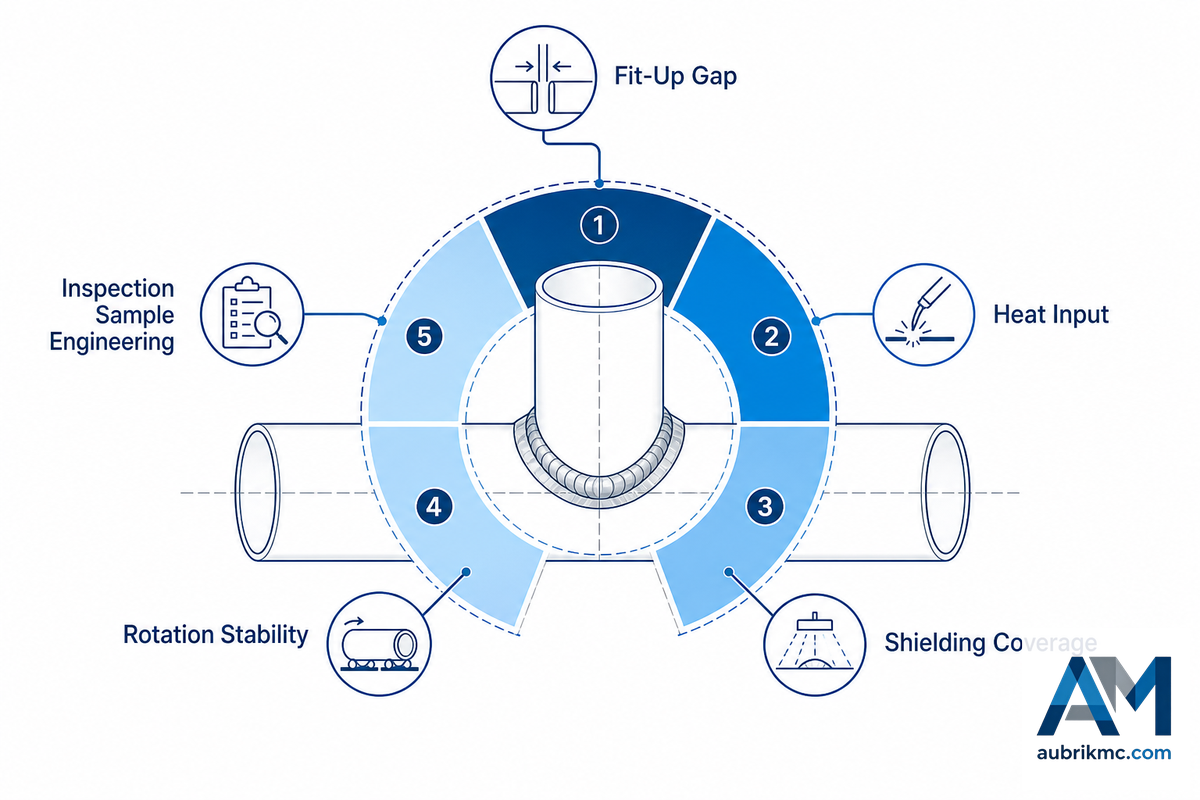
Tube fit-up and purge errors can turn a good power source into a poor joint. This is why the first attribute in the purchasing process is the 5-Failure Tube Joint Risk Map. It isn’t a defect rate measure. It’s a pragmatic way to associate the failure risk with a machine control and a purchasing question.
| Failure risk | Common trigger | Machine control to verify | Buyer question |
|---|---|---|---|
| Lack of penetration | Low heat input, poor program, or gap mismatch | Power source schedule and orbital weld speed | Can you show a sectioned sample on our wall thickness? |
| Excess heat input | Wrong current range or slow travel | Current program, pulse setting, heat balance | What heat-control record comes with the sample weld? |
| Poor purge or shield | Gas flow leak, wrong pre-purge time, blocked path | Shielding gas and purge timing | How is purge checked before production? |
| Misalignment | Oval tube, weak fixture, uneven clamp force | Weld head clamp and tube positioning | What OD tolerance can the clamp hold? |
| Repeatability drift | Operator reset, electrode wear, loose tooling | Recipe lock, electrode control, fixture maintenance | Can the system repeat 20 sample joints? |
| Tube collapse | Very thin wall and unsupported internal geometry | Support gas or backing method for edge cases | Is this a normal boiler tube or an ultra-thin research-like tube? |
| Over-cleaning delay | Unclear weld quality target | Inspection method agreed before the test | What is pass/fail before the trial starts? |
| Safety gap | Poor ventilation, guarding, or gas handling | Operator safety, guarding, and ventilation plan | Who owns safety checks during factory testing? |
| Code mismatch | Wrong acceptance route for boiler or piping work | Procedure, examination, and test documents | Which code or project spec governs the joint? |
Orbital welding can become a setup lesson instead of a buying decision if the purchaser doesn’t bring these risks forward early. Because each failure mode points to a different root cause, ask Aubrik to review the application with 20 sample joints, fixture notes, purge evidence, and inspection records. The TTW model selector can support the machine conversation, but the risk map gives the plant team a clearer specification before that discussion begins.
Orbital GTAW, Resistance Subtypes, and Manual TIG
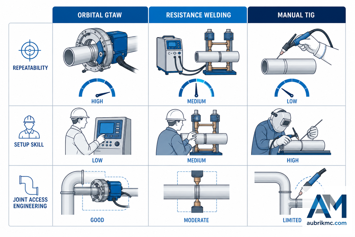
Many think that the “best” tube welding machine is the one with the highest level of automation. This isn’t always true. Orbital TIG, resistance spot or seam methods, portable or flash resistance welding, and manual TIG solve different problems.
The cheapest machine is almost never the best if it means rework, but the highest level of automation is equally inappropriate when joint access, material, or inspection method don’t align with it.
Orbital TIG works best for repeatable tube and pipe work when the tube can be rotated, the joint can be prepared, and the gas and arc can be precisely controlled. It excels for stainless, titanium, alloys, and high-precision tubing.
Various forms of resistance welding can be suitable for high-volume production when forces, times and current are controlled, although OSHA’s resistance welding guidelines are very clear about what comprises proper safety and operator standards for these devices. Manual TIG remains appropriate for repair, limited access, prototypes, manual welding after a failed clamp setup, and low-volume production.
Therefore, the conversation about your plant’s equipment selection should start with process fit, not an assumed ranking.
If you’re using any related manufacturing process, such as tube strip feeding or other boiler welding operations, compare the tube welding choice with the membrane panel welding machine and the SAW vs MIG/MAG comparator. They can exist in the same factory but shouldn’t have the same standard of evidence.
The practical tradeoff is that a production fixture, application volume, and inspection route should choose the process, not the other way around. For example, a 20-joint sample run can expose a purge or clamp problem that a current range cannot show. Aubrik can help compare TIG, orbital GTAW, and resistance subtype fit, while its factory and ISO 9001 context should still be paired with proof from the exact tube material.
Weld Head, Power Source, Diameter, and Wall Thickness Checks
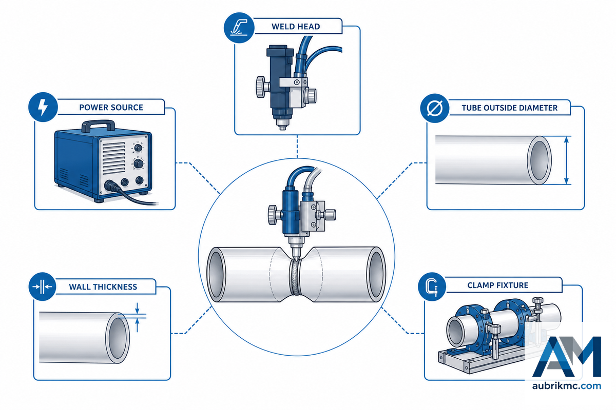
The weld head and gripping system tend to draw the most immediate buying attention, but the workholding method and power source often decide whether the machine is practical. Give the supplier the exact tube OD, wall thickness, alloy, fit-up gap, weld position, electrode size, welding power limit, wire feed need, gas flow plan, and whether the weld head can clear nearby fixtures.
Typical criteria for boiler and heat-exchanger tubes are OD range, clamp design, current range, duty cycle, cooling, program storage, and maintenance access. For thin-walled tubes, austenitic stainless steel, titanium, and nickel alloy work, also ask whether real-time monitoring is available for current schedule, rotation timing, gas flow, or alarm records. In a narrow edge case, academic work on ultra-thin titanium tubing below 500 micrometers shows that internal buttressing gas flow can help retain tube geometry while heat input creates penetration. That research shouldn’t be generalized to ordinary boiler tubes, but it’s a useful warning: wall thickness isn’t just a number in a table.
When developing a clean request for quote, list the values numerically rather than leaving them inside drawing notes: 15 mm minimum OD, 38 mm common trial OD, 76 mm mid-range OD, 114 mm large OD, 170 mm upper-range OD, 1.5 mm wall, 3 mm wall, 6 mm wall, 315 A current, 350 A current, 24 V control circuit review, 120 V external control limit review, 550 V high-voltage enclosure review, 15 psi pressure boundary discussion, 160 psi high-temperature water discussion, 250 degrees F temperature boundary, 120 degrees C temperature boundary, 30 min sample run, 8 hours shift plan, and 20 sample joints. These aren’t promised limits; they’re the sort of spec fields that keep the welding power discussion concrete.
Use Aubrik’s public 15-170 mm and 315-350 A range as a reference point, then test it against your own workpiece. If the plant still needs to define upstream boiler-panel bending and assembly, the panel bending machine and the boiler tube capability envelope calculator can help your team confirm geometry before the tube joint reaches welding. That step reduces fixture risk because weld-head fit often fails upstream, not at the arc.
Boiler and Heat-Exchanger Use Cases: Tube-to-Tube vs Tube-to-Tubesheet

Tube-to-tube and tube-to-tubesheet sound alike but are different buying intents. Tube-to-tube welding attaches two tubes or tube sections together. Tube-to-tube sheet welding attaches a tube to a sheet or plate and often involves different access, fixture, expansion, and inspection issues.
Commingling them may lead to incorrect weld head, incorrect clamp, and incorrect acceptance plan.
Put the governing-code boundary in the spec discussion. ASME BPVC Section I may matter for power boilers, ASME B31.1 can matter for power piping and boiler-external piping, and ASME B31.3 can matter for process piping and packaged equipment assembly. ASME Section IX, AWS D10.9/D10.9M, ASME Section V, OSHA 1910.252, and B31 piping standards don’t do the same job. The more honest version is that a machine helps make a weld; it doesn’t decide the code, examination method, or jurisdictional acceptance by itself.
Start production-line context with the boiler production equipment overview. Then move from this guide to Aubrik’s tube welding process selector or the solution overview when the project is ready for equipment selection.
This distinction prevents an expensive application mistake: a tube-to-tubesheet fixture problem may look similar to a tube-to-tube weld problem on a drawing, but the root cause and inspection plan are different. In production, ask Aubrik to check the application boundary with the drawing, code note, sample weld, and factory capability before treating either use case as the same machine requirement.
The 4-Point Weld Evidence Check
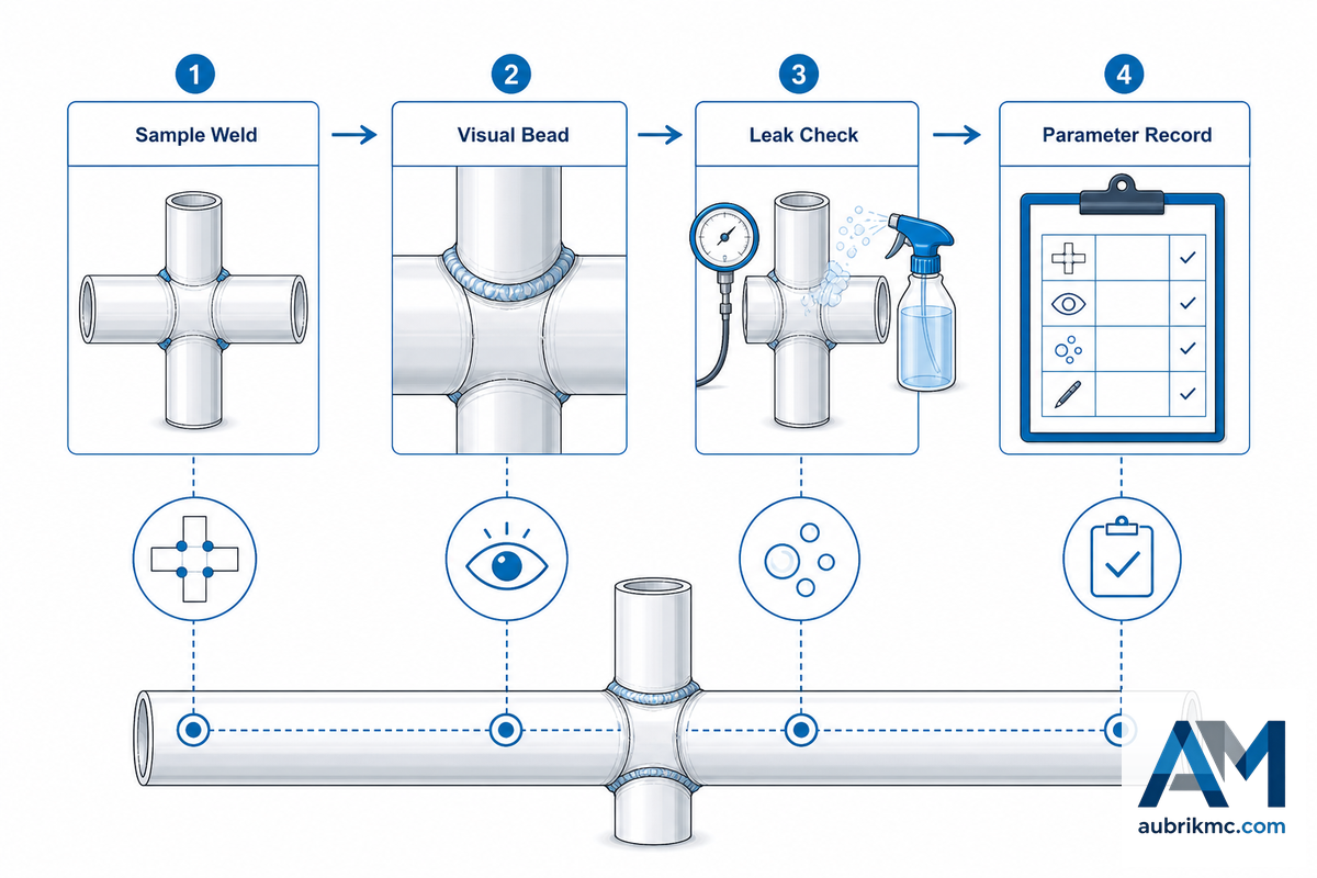
Defend your engineers from vague repeatability claims using the 4-Point Weld Evidence Check. When committing to a welding machine, request four lanes of evidence.
- Sample weld evidence: welded samples corresponding to your OD, wall thickness, material, joint prep, and production position.
- Procedure and qualification scope: WPS/PQR or project procedure context where required, with AWS or ASME references kept in their proper lane.
- Test and inspection methods to include visual inspection, sectioning / coupons, pressure or leak test, radiographic test, ultrasonic test or other NDE as required by the project.
- Proof of safe use and maintenance, purge/shielding gas mentioned, ventilation or confined space precautions, if applicable, trained operator, guards, and machine examination details.
OSHA 1910.252 supports welding safety context, including ventilation and confined-space concerns, not weld acceptance quality. ASME Section V supports the nondestructive examination lane, not machine capability. Welding procedures should also state whether the joint is autogenous, uses filler, or requires multi-pass welding, because those choices change heat input, inspection scope, and automated welding repeatability. That separation may feel counter-intuitive, but it’s what keeps the evidence package defensible for a production buyer.
Aubrik’s public company background is useful for supplier screening: Wuxi ABK Machinery presents Aubrik as a boiler and welding automation supplier with ISO 9001, CE, OEM support, and factory capability. Treat those as supplier qualifications, then still ask for project-specific weld proof. For broader fit checks, begin with the equipment selector.
Because evidence gaps often appear after a trial, keep the four lanes tied to one production application: sample joint, qualification scope, inspection route, and safety record. With a 20-joint sample, ISO 9001 supplier context, and clear project specification, Aubrik and the buyer share the same evidence base before a request for quote is finalized.
OD x Wall x Process and Support Matrix
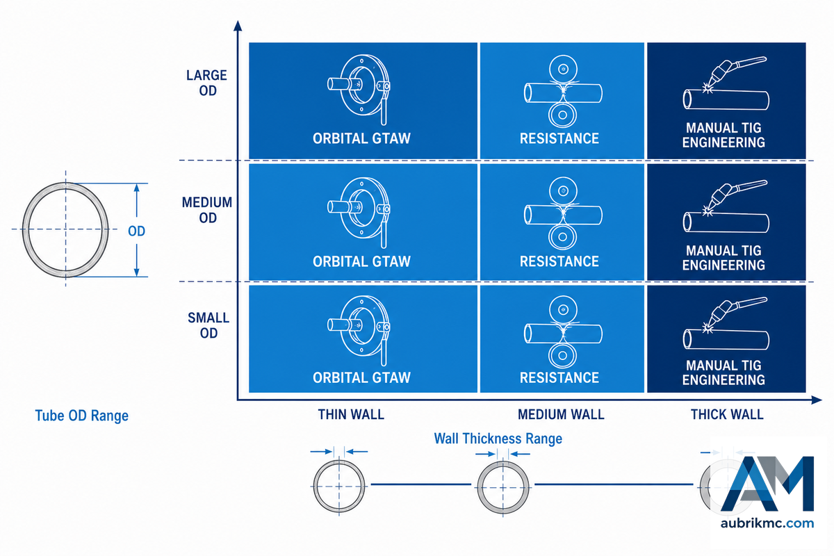
Think of it as a shortlist tool, not a definitive decree; The OD x Wall x Process and Support Matrix will keep your team from getting caught up comparing the price tag, or the number of amps, or the blanket “automatic welding” tag.
| Tube type or condition | Process category | Support or control issue | Evidence to request |
|---|---|---|---|
| Small OD, thin wall stainless | Orbital GTAW | Purge, heat input, clamp fit | Sample weld, purge log, section photo |
| Small OD, ultra-thin specialty tube | Special orbital GTAW review | Support gas and geometry stability | Application test, not a boiler-tube assumption |
| Medium OD, repeat production | Orbital GTAW or automated TIG | Recipe repeatability and electrode control | 20-joint repeat sample record |
| Large OD within weld head range | Orbital or mechanized TIG review | Head clearance and cooling | Drawing review plus duty-cycle note |
| High-volume seam-like work | Resistance seam subtype if designed for the joint | Electrode force, guarding, maintenance records | Safety and inspection record template |
| Flash or butt joining case | Flash resistance review | Ventilation and flash guard | OSHA-linked safety plan |
| Repair or access-limited work | Manual TIG | Operator skill and inspection method | Welder qualification and acceptance route |
| Boiler-external piping | Process chosen after code review | B31.1 or project code boundary | Engineer-approved scope note |
| Process-piping or packaged unit | Process chosen after code review | B31.3 or jurisdictional boundary | Inspection and test plan before purchase |
Use the row that matches your tube condition to expose the root cause of the buying problem. Small OD, 1.5 mm wall applications create a different risk from a 6 mm wall boiler-external piping case, because purge, support, fixture force, and inspection evidence change together. After the matrix narrows the application, use the orbital ROI calculator to model capacity and payback assumptions. If upstream forming is still uncertain, the material x bend radius decision tree can help your team lock geometry before the weld station requirement is finalized.
Buyer Trend: Weld Evidence, Not Just Amps

It’s tempting to call this a 2026 trend, but the safer statement is narrower: buyers are better served when they ask for weld evidence, not only amps. Search demand suggests that broader orbital welding terms carry more discovery demand than the exact tube-to-tube phrase, yet search volume doesn’t prove buyer behavior by itself.
Evaluation habits are where the practical trend show up. A buyer who asks only for current range may miss fixture, weld quality, purge, power supply, safety, and inspection problems. Teams that ask for sample welds, procedure context, shielding gas notes, NDE or test route, and maintenance records have a stronger basis for comparison. Aubrik’s role is to help translate that evidence into a machine configuration, especially when the plant has a boiler production line, OEM constraints, and repeatable tube processing needs.
During layout-level planning, pair this guide with Aubrik’s membrane SAW welding ROI and payback calculator and the membrane panel welder configuration selector. Those tools keep tube welding decisions tied to production capacity, not isolated catalog claims.
FAQ
These questions cover the most common production risks because weld head fit, shielding gas, power source control, and material scope are where quote assumptions often fail. Use the answers as an application checklist, then ask Aubrik to confirm the same points with sample welds, factory capability, ISO 9001/CE supplier context, and the exact tube OD and wall thickness.
What is orbital tube welding and when does it make sense over manual TIG?
Orbital tube welding uses a weld head to move the arc around a tube or pipe while the workpiece stays fixed. It makes sense when repeatability, access, purge control, and production volume justify a programmed welding process. Manual TIG still fits repair, prototype, short-run maintenance, and unusual access work where a closed orbital weld head can’t clamp or rotate safely.
How is the orbital weld head sized to fit different tube diameters?
A weld head is selected around tube OD, clamp range, clearance around the joint, wall thickness, and whether the head can rotate without hitting fixtures. Send drawings, photos, and sample tubes before treating a published diameter range as enough. Buyers should also confirm ovality, nearby obstruction distance, purge access, and whether the clamp can hold the tube without marking the workpiece.
What shielding gas is recommended for orbital GTAW on stainless steel tubing?
Argon is common for GTAW shielding, but the final plan depends on material, wall thickness, purge path, weld procedure, and project acceptance route. Ask the supplier to document shielding gas, purge timing, gas flow check, root-side protection, oxygen-control assumptions, and whether the same gas setup was used on the sample weld that will be judged by your inspection team.
Does orbital TIG require a dedicated power source?
Most orbital TIG systems use a power source that can control current schedule, pulse behavior, rotation timing, and program memory with the weld head. Matching the power supply to the weld head and application matters more than buying the highest current rating.
What materials can be welded with orbital GTAW equipment?
Common targets include stainless steel, carbon steel, titanium, nickel alloy, and other alloy tube or pipe work when the procedure, shielding, electrode, and fit-up are correct. Material weldability and acceptance should be confirmed by sample welds and the applicable project specification. A procurement team should also ask whether filler wire is needed, whether autogenous welding is allowed, how inert gas shielding is checked, and which inspection method will judge the final metal joint. Heat tint, oxidation, root profile, coupon sectioning, leak testing, and NDE requirements can change the answer even when two materials appear similar on a catalog sheet. That added scope prevents a material list from becoming an unsupported promise.
Next Step
When your team has OD, wall thickness, material, production volume, joint access, and evidence requirements ready, move from this guide to Aubrik’s Aubrik tube-to-tube welding equipment page. When the upstream boiler line is still open, start with the equipment selector and then return with a tighter spec brief.
References and Source Notes
- AWS D10.9/D10.9M piping and tubing qualification specification
- ASME BPVC Section IX welding, brazing, and fusing qualifications
- ASME BPVC Section V nondestructive examination
- ASME BPVC Section I power boilers
- ASME B31.1 power piping
- ASME B31.3 process piping
- OSHA 1910.252 welding, cutting, and brazing general requirements
- OSHA 1910.255 resistance welding
- arXiv: ultra-thin-walled titanium tubing GTAW modeling
- Google Patents: orbital weld head example
- Aubrik about page
- Aubrik tube to tube welding machine product page